Page is loading ...

Owner’s Manual
BONAIRE
®
Evaporative Air Conditioning
Installation Instructions
For help with installation or warranty issues call
1-800-939-2983 or www.bonaire-usa.com
For parts Visit our secure website www.bonairedurango.com
This product may qualify for rebates*
*Check with your local agency
Please keep this important manual in a safe place. It is the owner’s responsibility to
ensure that regular maintenance is carried out on this evaporative cooling product.
Failure to do so will void all guarantees beyond statutory and legal requirements.

INSTALLATION INSTRUCTIONS
2
Contents
INTRODUCTION…………………………………………………………………………….….3
UNIT LOCATION………………………………………………………………………………..6
UNIT INSTALLATION…………………………………………………………………………..7
UNIT INSTALLATION (SIDE DISCHARGE)………………………………………………..14
CHECK LIST…………………………………..………………………………………………..26
PROBLEM SOLVING……………………………………………………………………….…27
PARTS LIST…………………………………………………………………………………….28
MAINTENANCE………………………………………………………………………………...30
WARRANTY……………………………………………………………………………………..31
SERVICE………………………………………………………………………………………....33

INSTALLATION INSTRUCTIONS
3
1.0 Introduction
General Information
Thank you for purchasing a quality Bonaire Evaporative Cooler. We care about your safety and would
ask you to spend a few minutes reading these simple instructions before operating this product.
Safety!
Read carefully all of these instructions prior to operating the unit.
Read and Save these Instructions. Do not throw these Instructions away.
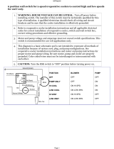
WARNING - TO REDUCE THE RISK OF FIRE, ELECTRIC SHOCK, OR
INJURY TO PERSONS, OBSERVE THE FOLLOWING:
Use this unit only in the manner intended by the manufacturer. Interference with and operation of
this cooler in any manner not prescribed by these instructions could cause a safety issue and WILL
void any warranty. If you have any questions, contact the manufacturer.
Before servicing or cleaning the unit, switch power off at the service panel and lock the service
disconnecting means to prevent power from being switched on accidentally. When the service
disconnecting means cannot be locked, securely fasten a prominent warning device, such as a tag,
to the service panel.
Installation work and electrical wiring must be done by qualified person(s) in accordance with all
applicable codes and standards, including fire-rated construction.
Do not use cooler on uneven or unstable surfaces.
When cutting or drilling into wall or ceiling, do not damage electrical wiring and other hidden
utilities.
Evaporative coolers must always be vented to the outdoors.
Use only with a 115V, 60Hz, 1 phase electrical supply.
Motor and pump have a grounded, molded plug and an automatic thermal overload which will stop
the motor operation if it overheats. The motor will restart again when it cools down.
The molded pump receptacle is for the grounded evaporative cooler pump only. Do not plug
anything else into this receptacle.
Do not alter or modify this cooler.
Do not allow children to operate or service this cooler.
WARNING: To reduce the risk of fire or electric shock, do not use this product with any solid state
speed control device.
Use only qualified electricians for replacement or servicing of switches, or electrical motors and
components in this cooler.
Always turn off power and unplug the fan motor and pump inside the cooler before installation or
maintenance and cleaning. More than one disconnect switch may be required to de-energise the
equipment for servicing
CAUTION: This unit has an unguarded impeller. Do not use in locations readily accessible to
people or animals.
Wiring shall be in accordance to the National Electrical Code, ANSI/NFPA 70

INSTALLATION INSTRUCTIONS
4
1.0 Introduction
Evaporative Cooling
The principal of your unit is to introduce fresh air, which is washed through the filter pads to
provide cool fresh air. The air is exhausted taking with it any heat loading on the home.
Exhaust
It is essential for successful operation of evaporative air-conditioning that there are sufficient
exhaust openings in the area to be ventilated. Open doors and windows will usually provide
this.
The minimum exhaust opening should be 8ft² for the 4,000 cfm and 10 ft² for the 5,000 cfm
unit.
5½ ft²
16 ft²
8 ft²
5½ ft²

INSTALLATION INSTRUCTIONS
5
1.0 Introduction
FAILURE TO COMPLY WITH THESE INSTRUCTIONS:
If this product is installed in a manner which is inconsistent with these installation instructions
or, if the product has been modified and or altered from its original form, we shall not be held
in any way liable to the purchaser of the product or any other person in connection with any
loss or damage that have may have been, or may in the future be, suffered or incurred as a
result of such incorrect installation or modification or alteration of the product.
Should you not follow these instructions the unit warranty may be void. The cost of warranty
would then be a cost to the customer or the installer / dealer.
Refer to the tick box Commissioning Checklist to ensure you have covered all points when
the installation is complete.
1.1 Important Notes
TEXT AND ILLUSTRATION COPYRIGHT CLIMATE TECHNOLOGIES Pty Ltd. 2016
All rights reserved. No part of this document may be reproduced or transmitted in any
form or by any means, electronic or mechanical, including photocopying, recording or
by any information storage and retrieval system, without prior permission in writing from
Climate Technologies.
Climate Technologies is constantly researching and developing improved product
features and therefore reserves the right to change the specifications without notice.
E. & O.E.
1.2 Before Commencing
Packaging – check there is no damage before removing packaging. Damaged units
should not be installed. Bonaire Customer Care Line should be contacted prior to
installation. Careless transportation by installer will not be covered by warranty.
Do not install damaged products. Contact the Bonaire Customer Care Line for
further advice.
Installed damaged products will not be covered by warranty.
Have you got all the system components?
Have you got the right unit?
Does the system design conform to the minimum specification of the sizing
specification and as such fall in line with sound engineering design practices?

INSTALLATION INSTRUCTIONS
6
2.0 Unit location
T LN
2.1 Unit Location Check List
EPA - A correctly installed unit will perform to specification on sound pressure radiated
noise. As an installer, you have a professional obligation to ensure that every practical
and reasonable effort is made to install this product to best practice guidelines and
ensure that any operational noise does not affect neighbours. Complying with EPA /
council by laws for noise abatement is the responsibility of the dealer / installer / owner.
NOTE: Do not mount the unit on a section of roof that slopes towards a
neighbour’s property.
Place the unit well away from sources of smoke, dust and objectionable fumes so that
only clean, fresh outside air will be drawn into the unit. Reference should be made to
relevant electric codes and state plumbing regulations.
Check the proposed location to ensure that building members are structurally capable
of supporting the operating weight of the air conditioner. You may need to consult the
roof truss manufacturer.
The unit must be installed in a position that gives safe access for service. It is the
responsibility of the dealer / installer to ensure safe access to the unit can be obtained
for servicing the product.
Where roof height, pitch or construction will cause OH&S concerns as previously
mentioned, service footing supports / platform and or harness anchorage must be
provided for safe service.
NOTE: The manufacturer and its service providers reserve the right to refuse
service unless safety and accessibility to the unit can be guaranteed.
The providing of any extra equipment required to give access to the unit for servicing or
warranty repairs is the responsibility of the owner.
The unit should face into the customer’s back yard, as low as possible on the roof,
with easy, unobstructed access. Keep the unit away from chimneys, flues and vents
that will pollute the filter pads and the fresh air being drawn into the house.

INSTALLATION INSTRUCTIONS
7
Unit Installation
3.1 Down Discharge installation
The evaporative cooler will be delivered with the fan motor assembly installed in “down
discharge” mode. See the image below.
The air will be directed downwards when installed in this configuration.
NOTE: This cooler is suitable for use with 17 ¾” and 19 ¾” duct sizes.
Down discharge configuration

INSTALLATION INSTRUCTIONS
8
Unit Installation
3.2 Electrical connections
NOTE: Use hand tools when refitting the screws, tightening the screws with power
tools can strip the screw holes.
3.2.1. Unscrew the thumb screws (transit screw) from the top of the grills.
3.2.2. Slide the removable grill upward and remove from the unit.

INSTALLATION INSTRUCTIONS
9
Unit Installation
3.2.3. To fit a Listed flexible conduit electrical supply cable electrical supply cable utilise
the 7/8” hole in the panel. For electrical connections, use a Listed, liquid tight, nonmetallic
flexible conduit connector, of suitable size for the panel conduit opening, and suitable for
outdoor use. Secure the connector to the panel with locking nut. See image below for
location.
3.2.4. Remove the 3 screws from the control box to access the fan motor and pump
wiring harness to allow connection of the wiring.
Control
box
Screw

INSTALLATION INSTRUCTIONS
10
Unit Installation
3.2.5. Connect the wiring as shown in the diagram below using a Listed Flexible conduit
to connect to the power supply.
WARNING:- Electrical connections should be performed by a qualified electrician so
that all electrical wiring conforms to local standards.
.

INSTALLATION INSTRUCTIONS
11
Unit Installation
3.3 Water connections
3.3.1 Connect the Float valve to the water supply. Note the float valve and connections
have been factory fitted requiring only water supply hose to be fitted to the external
connection fitting at the corner of the tank /base as shown in the image below.
Ensure all water connections are securely fastened to prevent leaks.
3.3.2 Installation of the bleed off hose is required to prevent mineral deposits in the
system. Adjust the bleed restrictor bracket to allow control of the bleed rate to suit
local supply water conditions. Adjust the bleed off to approximately 2 ½ gallons /
hour and adjust as necessary.
Float valve
assembly
Tank / base
External
connection
Slide hose this way
to reduce flow
Slide hose this way
to increase flow

INSTALLATION INSTRUCTIONS
12
Unit Installation
Ensure the cooler is level.
Adjust the mounting legs if necessary.
Turn the water on to the unit and allow the unit to fill.
Check water fittings do not leak.
Ensure float valve operates.
Fit the grill panels and check for even wetting of the filter pads.
Check bleed off rate.
Mounting legs

INSTALLATION INSTRUCTIONS
13
Unit Installation
IMPORTANT: During installation ensure that no holes are drilled into the water sump.
DO NOT DRILL INTO WATER SUMP
WATER SUMP

INSTALLATION INSTRUCTIONS
14
Unit Installation
3.4 Converting from Down Discharge to Side Discharge Installation
NOTE: Handle the fan/venturi assembly with care, as the fan blade is not protected by
the venturi once removed.
The evaporative cooler has been designed to allow for the discharge configuration to be
changed to “side discharge” mode.
The air will be directed to the side in this configuration.
a. Always turn off power and unplug the fan motor and pump inside the cooler before
installation or maintenance.
b. Remove the 2 screws from the each side of the cap to allow removal.
c. Remove and retain the cap.
d. Remove the lid screws and then remove the grills next to the side discharge grill.
Remove the
screw on each
side of cap
Cap

INSTALLATION INSTRUCTIONS
15
Unit Installation
e. Disconnect the motor and pump cables from control box plugs.
f. Remove the screws (4 places) from the grill on the opposite side to the side discharge
grill
Disconnect
plugs

INSTALLATION INSTRUCTIONS
16
Unit Installation
g. Remove the the grill on the opposite side to the side discharge grill
h. Remove the 3 screws fastening the lid to the Side discharge panel

INSTALLATION INSTRUCTIONS
17
Unit Installation
i. Remove the screws fastening the top of each post. Keep the screws to refit when
reassembling to cooler.
j. Remove the screws fastening the bottom of each post. Keep the screws.
k. Remove the lid and posts.
Note: Be careful as electrical box is still attached to the underside of the lid

INSTALLATION INSTRUCTIONS
18
Unit Installation
l. Remove the 2 screws securing the side discharge panel to the base.
With the retaining screws removed, lift the side discharge panel and place the panel in a
position where it cannot be damaged.
Remove
screw
Remove
screw

INSTALLATION INSTRUCTIONS
19
Unit Installation
m. Remove the tape fastening the fan assembly to the base. Carefully lift the fan from the
down discharge position.
n. Lay the side discharge panel down onto a surface that will not damage the panel.
o. Present the fan motor assembly to the side panel ensuring the flat section of the venturi
is at the bottom, aligned with the bottom of the panel.
Venturi flat
section
Panel
bottom
Remove tape

INSTALLATION INSTRUCTIONS
20
Unit Installation
p. Carefully introduce the fan motor assembly to the side panel.
NOTE: to fit the fan motor assy the motor arm support of the side panel will need to be
carefully flexed to get the motor arms in the correct positions (4 places).
q. Ensure motor arms are securely located by the “hooks” on the side panel motor arm
supports (4 places).
NOTE: Fan motor arms are on the “hook” side of the side panel motor arm support (4
places) as shown in the image below.
Side panel
motor arm
support
Fan motor
arm
Motor arm
located in
support
“hook”
/