GROHE 25 083 000 Installation guide
- Category
- Faucets
- Type
- Installation guide

English .....1
Français .....2
Español .....3
Design & Quality Engineering GROHE Germany
96.386.231/ÄM 217300/06.10
Allure
Allure
25 083
25 097

I
25 097
S.v.p remettre cette instruction à l'utilisateur de la robinetterie!
Sirvanse pasar ese instrucción al utilizador de la grifería!
Please pass these instructions on to the end user of the fitting!
25 097
25 083 25 083
Page is loading ...

1
English
Application
Operation is possible in conjunction with:
• Pressurized storage heaters
• Thermally controlled instantaneous heaters
• Hydraulically controlled instantaneous heaters
Operation with low-pressure storage heaters (displacement
water heaters) is not possible.
Specifications
• Max. flow
- Spout approx. 60 L/min or 13.2 gpm
- Handshower max. 9.5 L/min or 2.5 gpm
• Flow pressure
-min. 7.25 psi
- recommended 14.5 - 72.5 psi
- greater than 72.5 psi, fit with pressure reducing valves
• Max. operating pressure 145 psi
• Test pressure 232 psi
• Temperature
- max. (hot water inlet) 176 °F
• Water connection cold - Right hand
hot - Left hand
Note
• Installation of backflow protection must comply with local
codes and regulations.
• An access panel must be provided for access to diverting
unit and hose connections.
• Major pressure differences between cold and hot water
supply should be avoided.
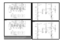
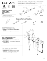
Installation
Layout dimensions to establish centers and proper clearences,
see dimensional drawing on fold-out page I.
Before soft-soldering:
Prepare components.
Side valves, see fold-out page II, fig. [1a], [1b] and [2].
Screw out the ceramic cartridge (A), see fig. [1a], [1b].
Fit side valves to deck, the distance from the top of the side
valve body to deck must be 5/16", see fig. [2].
Diverter, see fig. [2] and [4].
Loosen cap (B) and detach escutcheon (C), see fig. [4].
Screw out diverter cartridge (D) and unscrew connection
nipple (E).
Fit diverter to deck, the distance from the top of the diverter
body to deck must be 5/16", see fig. [2].
Spout, see fig. [5].
Lever out plug (O).
Remove set screw (N)- not only loosen!
Remove spout (M) with disc (M1) and O-ring (M2).
Install shank (F) with sealing set (G).
Before mortar and tile is applied, wrap exposed parts with tape
to protect threads and opening.
Estimate height of tile level and adjust spout shank for proper
fit, make sure that tape holds up upper washer and O-ring so
that tile can be fitted underneath.
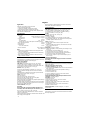
Connect wideset, see fig. [6].
Important!
Do not solder the connections between the pipes and
valve body unless all internal parts are removed (parts A,
B, D, E and M), see figs. [1a], [1b], [4] and [5].
The spout, side valves and diverter can now be connected
with 3/4" copper tubing.
The hot water supply should be connected on the left, the cold
water supply on the right side.
Water must flow in the direction of the arrows cast into the
body of the side valves and diverter.
Final Installation
Side valves, fold-out page II, fig. [1a], [1b] and [3a], [3b].
1.Screw cartridge (A) into the body, see fig. [1a], [1b].
2.Fit extension (H), escutcheon (I), spindle & sleeve (J).
3.Push on handle (K), see fig. [3a], [3b].
25 083:
4.Secure with screw (K1), see fig. [3a].
Diverter, see fig. [4].
1.Screw in nipple (E).
2.Fit diverter cartridge (D), escutcheon (C) with cap (B).
3.Install diverter handle (L). The distance from the top of the
cartridge spindle to deck must be 2''.
Spout, see fig. [5].
1.Put disc (M1) on the shank of the spout and install
O-ring (M2).
2.Attach spout (M) to the shank (F) and insert set screw (N)
using a 3mm allen wrench.
3.Fit plug (O).
Handspray, see fig. [7] and [8].
1.Attach hose guide (P) using mounting and sealing set (P1),
see fig. [7].
2.Fit escutcheon (P2) with adapter (P3).
3.Connect shower hose (Q) to nipple (E), see fig. [8].
4.Fit shower hose (Q) through hose guide (P) from below.
5.Screw taper nut (Q1) onto shower hose (Q).
6.Place seal (R) in taper nut (Q1) and fit handspray (S) to
taper nut (Q1).
Flush pipes thoroughly!
Open cold and hot water supply and check connections
for leakage.
Maintenance
Inspect and clean all parts, replace as necessary and grease
with special grease.
Shut off cold and hot water supply!
I. Ceramic cartridge, see fig. [1a], [1b].
1.Pull off handle (K). 25 083: Loosen set screw (K1) with 2mm
allen wrench first.
2.Completely remove pre-mounted spindle & sleeve (J).
3.Remove escutcheon (I).
4.Unscrew extension (H).
5.Unscrew cartridge (A) using a 17mm socket wrench.
6.Change complete cartridge (A).
Observe the different replacement part numbers of the
cartridges, see fold-out page I.
II. Diverter, see fig. [4].
1.Remove cap (L1).
2.Remove nut (L2) using a 7mm socket wrench.
3.Detach diverter knob (L3).
4.Remove cap (B) using a 19mm open-ended wrench.
5.Remove escutcheon (C).
6.Remove diverter (D) using a 17mm socket wrench.
Assemble in reverse order.
Replacement parts, see fold-out page II ( * = special
accessories).
Care
Instructions for care of this faucet will be found in the Limited
Warranty supplement.
Page is loading ...
Page is loading ...
Page is loading ...

Grohe Canada Inc.
1230 Lakeshore Road East
Mississauga, Ontario
Canada, L5E 1E9
Technical Services
Services Techniques
Phone/Tél: 905/271-2929
Fax/Télécopieur: 905/271-9494
Grohe America Inc.
241 Covington Drive
Bloomingdale, IL
60108
U.S.A.
Technical Services
Phone: 630/582-7711
Fax: 630/582-7722
www.grohe.com
-
 1
1
-
 2
2
-
 3
3
-
 4
4
-
 5
5
-
 6
6
-
 7
7
-
 8
8


GROHE 25 083 000 Installation guide
- Category
- Faucets
- Type
- Installation guide
Ask a question and I''ll find the answer in the document
Finding information in a document is now easier with AI
in other languages
- français: GROHE 25 083 000 Guide d'installation
- español: GROHE 25 083 000 Guía de instalación
Related papers
-
GROHE 27070000 Installation guide
-
-
-
-
-
-
-
-
-
Other documents
-
Moen 6100 SERIES User manual
-
Hans Grohe Starck X 10074001 User manual
-
Axor 35807801 User manual
-
 Brizo 6716814-BN Maintenance And Installation Manual
-
Kohler 9530-AF Installation guide
-
American Standard 4145SSF Installation guide
-
roco LOGICA User manual
-
Symmons S-66-2-STN-LAM-TRM-RP Installation guide
-
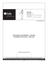 Kalia RUSTIK BF1487 User guide
-
Teka Universe Pro Duschkopf Owner's manual

