Symmons S-6612-STN-1.0 Installation guide
- Category
- Sanitary ware
- Type
- Installation guide

Unity
®
Model Numbers
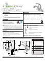
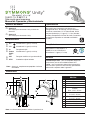
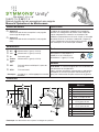
Single Handle Centerset Lavatory Faucet
Operation & Maintenance Manual
S-6610-1.5, S-6612-1.5
Single handle centerset lavatory faucet featuring a
4" mounting conguration. Includes ceramic cartridge,
1/4" copper supply lines, 1/2" IPS inlet connections,
50/50 drain assembly and standard 1.5 gpm (5.7 L/min)
aerator. Components made from brass and nonmetallic
materials plated in standard polished chrome nish.
Specification
Dimensions
Note: Dimensions subject to change without notice.
-0.5 0.5 gpm (1.9 L/min) aerator
-1.0 1.0 gpm (3.8 L/min) aerator
-G Grid drain
-Delete
Suffix
1.5
2.2 gpm (8.3 L/min) aerator
-MP Metal pop-up drain in place of standard
-STN Satin Nickel finish
Modifications
Note: Append appropriate -sufx to model number.
CG
CG
S-6610-1.5
Unity Single Handle Centerset Lavatory Faucet
Less Rod
S-6612-1.5
Unity Single Handle Centerset Lavatory Faucet
Measurements
A 6-5/8", 168 mm
B 3-3/8", 86 mm
C 5-7/8", 149 mm
D 4-1/2", 114 mm
E
Deck Thickness Ref.
Max. 1-3/8", 35 mm
F
Hole Size
Ø 1-3/8", 35 mm
G
(2x) Hole Size
Ø 1-1/2", 38 mm
H 3-1/4", 83 mm
I 5-3/4", 146 mm
J Min. 2-1/2", 64 mm
K 1/2-14 NPSM
BB
CC
EE
HH
II
JJ
GG
AA
FF
DD
KK
Compliance
Certied by
CSA Group
-NSF/ANSI 372, NSF/ANSI 61.9
-ASME A112.18.1/CSA B125.1
-WaterSense 1.5 gpm (5.7 L/min)
Warranty
Limited Lifetime - to the original end purchaser in
consumer/residential installations.
5 Years - for industrial/commercial installations.
Refer to www.symmons.com/warranty for complete
warranty information.
WARNING: This product can expose you to chemicals
including lead, which is known to the state of California to
cause cancer, birth defects, or other reproductive harm.
For more information, go to www.P65Warnings.ca.gov.

2
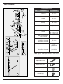
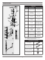
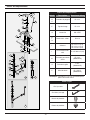
*Note: Append -STN to part number for Satin Nickel
nish.
Replacement Parts
Item Description Part Number
A
B
C
Handle Kit RL-212*
E Lift Rod RL-213*
G Cartridge KN-4-EXT
K
L
N
Mounting Hardware RL-214
I Aerator
RL-215-2.2* (2.2)
RL-215-1.5* (1.5)
RL-215-1.0* (1.0)
RL-215-0.5* (0.5)
I
Non-Aerated Laminar
Flow Restrictor
RL-215-NA-0.5* (0.5)
M
50/50 Drain Assembly
Metal Drain Assembly
RL-223*
(S-6612-1.5)
O Grid Drain Assembly
P-26*
(S-6610-1.5)
P Metal Drain Assembly
RL-154LR*
(S-6610-1.5)
Tools Required
Adjustable wrench
Allen wrench (3/32”)
Plumber putty
Plumber tape
A
H
C
K
M1
M2
M3
M8
M14
M4
M5
M6
M7
M9
M10
M13
M11
M12
D
E
F
G
I
B
J
L
N
M
O
P
Parts Breakdown

3
J
H
N
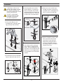
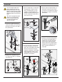
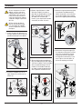
2) Place brackets (K) onto threaded
rods (J) and secure with nuts (L).
1
1
2
J
K
L
If replacing an older faucet
ensure water supply is turned
OFF before removing, then
turn faucet control valve ON to
relieve water pressure.
1) Insert faucet body (H) and
threaded rods (J) through mount-
ing gasket (N) and sink holes.
3) Seat ange (M2) into sink (M3
gasket optional). Install gasket
(M4), washer (M5) and nut (M6)
onto ange (M2) from below sink,
but do not secure nut. Screw on
tail piece (M7) and hand tighten.
2
3
M2
M7
PLUMBER
PUTTY
OPTIONAL
M3
M4
M5
M6
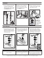
4) Turn tail piece (M7) and ange
(M2) so pivot is facing toward
faucet. Pull assembly down into
drain hole. Secure hardware from
below sink. Install stopper (M1) in
the removable or non-removable
position.
2
3
M7
PIVOT
M2
M1
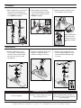
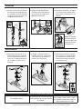
5) Attach inner washer (M8), pivot
rod (M9) and outer washer (M10)
to tailpiece (M7). Hand tighten nut
(M11) to secure pivot rod (M9).
M9
M7
1
M8
M10
M11
2
6) Connect lift rod (E) to clevis strap
(M13) and secure with thumb
screw (M14). Insert pivot rod
(M9) through spring clip (M12)
and clevis strap (M13). Secure
with spring clip (M12) and adjust
linkage if necessary.
3
4
4
M12
M9
M13
2
M14
M13
1
E
Installation
DO NOT use pipe dope
or thread sealant on drain
assembly, or any plastic
threaded components.

Symmons Industries, Inc. ■ 31 Brooks Drive ■ Braintree, MA 02184 ■ Phone: (800) 796-6667 ■ Fax: (800) 961-9621
Copyright © 2019 Symmons Industries, Inc. ■ symmons.com ■ [email protected] ■ ZV-3117 REV G ■ 052019
Troubleshooting Chart
Finish is spotting.
Elements in water supply may cause
water staining on nish.
Clean nished trim area with a soft
cloth using mild soap and water or a
non-abrasive cleaner and then quickly
rinse with water.
7) Attach supply lines to 1/2” IPS inlet
connections on faucet body (H).
Using a wrench, nish with one half
turn. DO NOT overtighten.
1
1
2
I
Maintenance
1) Remove plug button (C) and
set screw (B). Turning counter-
clockwise, disassemble handle
(A), collar (D) and nut (F) from
cartridge (G).
B
C
A
D
F
G
2) Remove cartridge (G) from faucet
body (H). Inspect for debris.
Replace cartridge if necessary.
G
H
3) Correctly align cartridge (G) and
insert into faucet body (H). Install
handle assembly following step 1
in reverse.
1
1
1
1
4
2
H
8) Attach supply lines to shut-off
valves and hand tighten. Using a
wrench, nish with one-half turn.
DO NOT overtighten.
1
1
2
9) Remove aerator (I) and ush lines
free of debris. Check for leaks.
H
B
C
A
D
F
G
1
Installation
Note: Counterclock-
wise to lower tem-
perature, clockwise
to increase tempera-
ture.
Page is loading ...
Page is loading ...
Page is loading ...
Page is loading ...
Page is loading ...
Page is loading ...
Page is loading ...
Page is loading ...
-
 1
1
-
 2
2
-
 3
3
-
 4
4
-
 5
5
-
 6
6
-
 7
7
-
 8
8
-
 9
9
-
 10
10
-
 11
11
-
 12
12


Symmons S-6612-STN-1.0 Installation guide
- Category
- Sanitary ware
- Type
- Installation guide
Ask a question and I''ll find the answer in the document
Finding information in a document is now easier with AI
in other languages
Related papers
-
Symmons SLS-0488-1.0 Installation guide
-
-
-
-
-
-
-
Symmons SLW-3512-MB-1.0 User manual
-
-
Other documents
-
American Standard Ceramix Centerset Lavatory Faucet 2000.115 User manual
-
American Standard 7416201.295 Installation guide
-
-
-
BWE 9233 User manual
-
Project Source F5121066CP Installation guide
-
Delta 25930 User manual
-
GROHE 20583000 Installation guide
-
Design House 545517 Installation guide
-
Signature Hardware 329378 Installation guide