SUPER MICRO Computer 2042G-6RF User manual
- Category
- Server barebones
- Type
- User manual
This manual is also suitable for

A+ SERVER
2042G-TRF
2042G-6RF
SUPER
®
USER’S MANUAL
Revision 1.0c

The information in this User’s Manual has been carefully reviewed and is believed to be accurate.
The vendor assumes no responsibility for any inaccuracies that may be contained in this document,
makes no commitment to update or to keep current the information in this manual, or to notify any
person or organization of the updates. Please Note: For the most up-to-date version of this
manual, please see our web site at www.supermicro.com.
Super Micro Computer, Inc. ("Supermicro") reserves the right to make changes to the product
described in this manual at any time and without notice. This product, including software and
documentation, is the property of Supermicro and/or its licensors, and is supplied only under a
license. Any use or reproduction of this product is not allowed, except as expressly permitted by
the terms of said license.
IN NO EVENT WILL SUPERMICRO BE LIABLE FOR DIRECT, INDIRECT, SPECIAL, INCIDENTAL,
SPECULATIVE OR CONSEQUENTIAL DAMAGES ARISING FROM THE USE OR INABILITY TO
USE THIS PRODUCT OR DOCUMENTATION, EVEN IF ADVISED OF THE POSSIBILITY OF
SUCH DAMAGES. IN PARTICULAR, SUPERMICRO SHALL NOT HAVE LIABILITY FOR ANY
HARDWARE, SOFTWARE, OR DATA STORED OR USED WITH THE PRODUCT, INCLUDING THE
COSTS OF REPAIRING, REPLACING, INTEGRATING, INSTALLING OR RECOVERING SUCH
HARDWARE, SOFTWARE, OR DATA.
Any disputes arising between manufacturer and customer shall be governed by the laws of Santa
Clara County in the State of California, USA. The State of California, County of Santa Clara shall
be the exclusive venue for the resolution of any such disputes. Super Micro's total liability for all
claims will not exceed the price paid for the hardware product.
FCC Statement: This equipment has been tested and found to comply with the limits for a Class
A digital device pursuant to Part 15 of the FCC Rules. These limits are designed to provide
reasonable protection against harmful interference when the equipment is operated in a commercial
environment. This equipment generates, uses, and can radiate radio frequency energy and, if not
installed and used in accordance with the manufacturer’s instruction manual, may cause harmful
interference with radio communications. Operation of this equipment in a residential area is likely
to cause harmful interference, in which case you will be required to correct the interference at your
own expense.
California Best Management Practices Regulations for Perchlorate Materials: This Perchlorate
warning applies only to products containing CR (Manganese Dioxide) Lithium coin cells. “Perchlorate
Material-special handling may apply. See www.dtsc.ca.gov/hazardouswaste/perchlorate”
WARNING: Handling of lead solder materials used in this
product may expose you to lead, a chemical known to
the State of California to cause birth defects and other
reproductive harm.
Manual Revision 1.0c
Release Date: June 30, 2011
Unless you request and receive written permission from Super Micro Computer, Inc., you may not
copy any part of this document.
Information in this document is subject to change without notice. Other products and companies
referred to herein are trademarks or registered trademarks of their respective companies or mark
holders.
Copyright © 2011 by Super Micro Computer, Inc.
All rights reserved.
Printed in the United States of America

Preface
About This Manual
This manual is written for professional system integrators and PC technicians. It
provides information for the installation and use of the A+ SERVER 2042G-TRF/6RF.
Installation and maintenance should be performed by experienced technicians
only.
The A+ SERVER 2042G-TRF/6RF is a high-end quad processor server based
on the SC828TS+-R1400LPBP 2U rackmount server chassis and the Super
H8QG6/i-F serverboard. The H8QG6/i-F supports four AMD 6000 processors.
Please refer to our web site for an up-to-date list of supported processors.
The A+ SERVER 2042G-TRF contains an H8QGi-F serverboard without SAS2
features while the A+ SERVER 2042G-6RF contains an H8QG6-F serverboard
with SAS2 features.
Manual Organization
Chapter 1: Introduction
The fi rst chapter provides a checklist of the main components included with the
server system and describes the main features of the Super H8QG6/i-F serverboard
and the SC828TS+-R1400LPBP chassis.
Chapter 2: Server Installation
This chapter describes the steps necessary to install the A+ SERVER
2042G-TRF/6RF into a rack and check out the server confi guration prior to powering
up the system. If your server was ordered without the processor and memory
components, this chapter will refer you to the appropriate sections of the manual
for their installation.
Chapter 3: System Interface
Refer to this chapter for details on the system interface, which includes the functions
and information provided by the control panel on the chassis as well as other LEDs
located throughout the system.
Chapter 4: System Safety
You should thoroughly familiarize yourself with this chapter for a general overview
of safety precautions that should be followed when installing and servicing the A+
SERVER 2042G-TRF/6RF.
iii
Preface

A+ SERVER 2042G-TRF/6RF User's Manual
iv
Chapter 5: Advanced Serverboard Setup
Chapter 5 provides detailed information on the H8QG6/i-F serverboard, including the
locations and functions of connectors, headers and jumpers. Refer to this chapter
when adding or removing processors or main memory and when reconfi guring the
serverboard.
Chapter 6: Advanced Chassis Setup
Refer to Chapter 6 for detailed information on the SC828TS+-R1400LPBP 2U
rackmount server chassis. You should follow the procedures given in this chapter
when installing, removing or reconfi guring SAS or peripheral drives and when
replacing system power supply units and cooling fans.
Chapter 7: BIOS
The BIOS chapter includes an introduction to BIOS and provides detailed information
on running the CMOS Setup Utility.
Appendix A: BIOS Error Beep Codes
Appendix B: Installing Windows
Appendix C: System Specifi cations

v
Preface
Notes

vi
A+ SERVER 2042G-TRF/6RF User's Manual
Table of Contents
Chapter 1 Introduction
1-1 Overview .........................................................................................................1-1
1-2 Serverboard Features .....................................................................................1-2
Processors ...................................................................................................... 1-2
Memory ........................................................................................................... 1-2
SAS (AS-2042G-6RF Only) ............................................................................ 1-2
Serial ATA ........................................................................................................1-2
PCI Expansion Slots .......................................................................................1-2
Ethernet Ports .................................................................................................1-3
Onboard Controllers/Ports .............................................................................. 1-3
Graphics Controller .........................................................................................1-3
IPMI .................................................................................................................1-3
UIO ..................................................................................................................1-3
Other Features ................................................................................................1-3
1-3 Server Chassis Features ................................................................................ 1-4
System Power .................................................................................................1-4
SAS/SATA Subsystem .....................................................................................1-4
Front Control Panel .........................................................................................1-4
I/O Backplane ..................................................................................................1-4
Cooling System ...............................................................................................1-4
1-4 Contacting Supermicro ....................................................................................1-6
Chapter 2 Server Installation
2-1 Overview .............................................................................................................2-1
2-2 Unpacking the System ....................................................................................2-1
2-3 Preparing for Setup .........................................................................................2-1
Choosing a Setup Location ............................................................................. 2-2
Rack Precautions ............................................................................................2-2
Server Precautions .......................................................................................... 2-2
Rack Mounting Considerations ....................................................................... 2-3
Ambient Operating Temperature ................................................................ 2-3
Reduced Airfl ow .........................................................................................2-3
Mechanical Loading ................................................................................... 2-3
Circuit Overloading .....................................................................................2-3
Reliable Ground .........................................................................................2-3
2-4 Installing the System into a Rack ................................................................... 2-4
Identifying the Sections of the Rack Rails .....................................................2-4

vii
Table of Contents
Installing the Inner Rails ................................................................................. 2-4
Installing the Outer Rails ................................................................................. 2-4
Locking Tabs ..............................................................................................2-4
Installing the Server into the Rack .................................................................. 2-5
2-5 Checking the Serverboard Setup .................................................................... 2-6
2-6 Preparing to Power On ...................................................................................2-7
Chapter 3 System Interface
3-1 Overview .........................................................................................................3-1
3-2 Control Panel Buttons .....................................................................................3-1
Reset ...............................................................................................................3-1
Power ..............................................................................................................3-1
3-3 Control Panel LEDs ........................................................................................ 3-2
Power Fail ....................................................................................................... 3-2
Overheat/Fan Fail ........................................................................................... 3-2
NIC2 ................................................................................................................3-2
NIC1 ................................................................................................................3-2
HDD ................................................................................................................. 3-3
Power ..............................................................................................................3-3
3-4 SAS Drive Carrier LEDs ................................................................................. 3-3
Chapter 4 System Safety
4-1 Electrical Safety Precautions ..........................................................................4-1
4-2 General Safety Precautions ............................................................................4-2
4-3 ESD Precautions .............................................................................................4-3
4-4 Operating Precautions .................................................................................... 4-4
Chapter 5 Advanced Serverboard Setup
5-1 Handling the Serverboard ...............................................................................5-1
Precautions ..................................................................................................... 5-1
Unpacking ....................................................................................................... 5-2
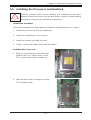
5-2 Serverboard Installation ..................................................................................5-2
5-3 Connecting Cables ..........................................................................................5-3
Connecting Data Cables .................................................................................5-3
Connecting Power Cables .............................................................................. 5-3
Connecting the Control Panel ......................................................................... 5-3
5-4 I/O Ports ..........................................................................................................5-4
5-5 Installing the Processor and Heatsink ............................................................ 5-5
Installing a Passive CPU Heatsink ................................................................. 5-7
5-6 Installing Memory ............................................................................................ 5-8
2-4 Installing Memory ............................................................................................ 5-8

viii
A+ SERVER 2042G-TRF/6RF User's Manual
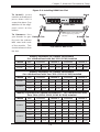
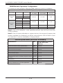
DIMM Module Population Confi guration ..................................................5-10
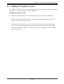
5-7 Adding PCI Add-On Cards .............................................................................5-11
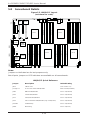
5-8 Serverboard Details ...................................................................................... 5-12
5-9 Connector Defi nitions ...................................................................................5-14
5-10 Jumper Settings ............................................................................................5-20
Explanation of Jumpers ................................................................................ 5-20
5-11 Onboard Indicators ........................................................................................5-23
5-12 SAS and SATA Drive Connections ............................................................... 5-24
5-13 Enabling SATA RAID ..................................................................................... 5-25
Serial ATA (SATA)..........................................................................................5-25
Installing the OS/SATA Driver ....................................................................... 5-25
Building a Driver Diskette ......................................................................... 5-25
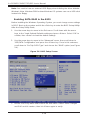
Enabling SATA RAID in the BIOS ................................................................. 5-26
Using the Adaptec RAID Utility .....................................................................5-27
Installing the RAID Driver During OS Installation ......................................... 5-27
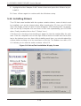
5-14 Installing Drivers ............................................................................................5-28
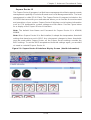
Supero Doctor III ........................................................................................... 5-29
Chapter 6 Advanced Chassis Setup
6-1 Static-Sensitive Devices ..................................................................................6-1
Precautions ..................................................................................................... 6-1
Unpacking ....................................................................................................... 6-1
6-2 Control Panel ..................................................................................................6-2
6-3 System Fans ...................................................................................................6-2
System Fan Failure ......................................................................................... 6-3
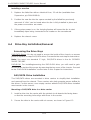
Replacing System Fans ..................................................................................6-3
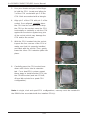
6-4 Drive Bay Installation/Removal .......................................................................6-4
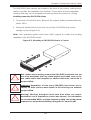
Accessing the Drive Bays ...............................................................................6-4
SAS/SATA Drive Installation ............................................................................6-4
SAS/SATA Drive Backplane ............................................................................6-7
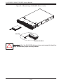
DVD-ROM Drive Installation ........................................................................... 6-7
6-5 Power Supply .................................................................................................. 6-8
Power Supply Failure ......................................................................................6-8
Removing/Replacing the Power Supply ..........................................................6-8
Chapter 7 BIOS
7-1 Introduction ......................................................................................................7-1
7-2 Main Menu ...................................................................................................... 7-2
7-3 Advanced Settings Menu ................................................................................7-2
7-4 Security Settings Menu .................................................................................7-12

7-5 Boot Settings Menu ....................................................................................... 7-13
7-6 Exit Menu ......................................................................................................7-14
Appendix A BIOS Error Beep Codes
Appendix B Installing Windows
B-1 Installing Windows to a RAID System ............................................................B-1
B-2 Installing Windows to a Non-RAID System ....................................................B-2
Appendix C System Specifi cations
Table of Contents
ix

x
Notes
A+ SERVER 2042G-TRF/6RF User's Manual

Chapter 1
Introduction
1-1 Overview
The A+ SERVER 2042G-TRF/6RF is a high-end server that is comprised of
two main subsystems: the SC828TS+-R1400LPBP 2U server chassis and the
H8QG6/i-F quad processor serverboard. Please refer to our web site for information
on operating systems that have been certifi ed for use with the A+ SERVER
2042G-TRF/6RF (www.supermicro.com).
In addition to the serverboard and chassis, various hardware components have been
included with the A+ SERVER 2042G-TRF/6RF, as listed below:
One (1) Mini-SATA to USB adapter for slim DVD (CDM-USATA-G-O-P)•
One (1) Slim SATA DVD kit (MCP-260-00027-0N)•
One (1) Black slim SATA DVD, TEAC or Panasonic (DVM-TEAC-DVD-SBT or •
DVM-PNSC-DVD-SBT)
Four (4) 2U Passive CPU Heatsinks for AMD Socket G34 (SNK-P0043P)•
One (1) USB/COM port tray (MCP-220-00007-01)•
SAS/SATA Accessories:•
One (1) SAS/SATA backplane (BPN-SAS-828TQ)
Two (2) 61.5-cm 8pin to 8pin cables for SGPIO (CBL-0157L-01)
Two (2) 48-cm SATA round cables (CBL-0227L)
Two (2) 55-cm SATA round cables (CBL-0228L)
Two (2) 65-cm SATA round cables (CBL-0230L)
One (1) 70-cm Internal USB cable for slim USB DVD-ROM (CBL-0341L)
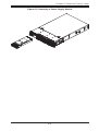
Six (6) hot-swap drive carriers (MCP-220-00001-01)
Chapter 1: Introduction
1-1

1-2
A+ SERVER 2042G-TRF/6RF User's Manual
1-2 Serverboard Features
At the heart of the A+ SERVER 2042G-TRF/6RF is one H8QG6/i-F quad processor
serverboard, which is based on the AMD SR5690/SP5100 chipset.
Below are the main features of the serverboards.
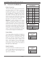
Processors
The H8QG6/i-F supports four AMD Opteron 6100 series (Socket G34 type)
processors. Please refer to our web site for a complete listing of supported
processors (www.supermicro.com).
Memory
The H8QG6/i-F has thirty-two (32) single/dual/tri/quad channel DIMM slots
supporting up to 512 GB of DDR3-1333/1066/800 registered ECC or 128GB of
DDR3 Unbuffered ECC/non-ECC SDRAM.. See Chapter 5 Section 6 for more details
on installing memory into the system.
SAS (AS-2042G-6RF Only)
An LSI 2008 SAS2 controller is integrated into the H8QG6-F to provide an eight
port SAS (Serial Attached SCSI) subsystem, which is RAID 0, 1, and 10 supported.
(Optional RAID 5 support is available with the iButton installed.) The SAS drives
are hot-swappable units. SR and IT modes are supported but not IR.
Note: The operating system you use must have RAID support to enable the
hotswap capability and RAID function of the SAS drives.
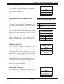
Serial ATA
The South Bridge (SP5100) of the chipset includes a Serial ATA controller for six
3Gb/s SATA drives. The hot-swappable SATA drives are connected to a backplane
that provides power, bus termination and confi guration settings. RAID 0, 1, and 10
are supported. Refer to the support area of our web site for procedures on setting
up RAID on your system.
PCI Expansion Slots
The H8QG6/i-F board has two PCI Express 2.0 x16 slots and two PCI Express 2.0
x8 slots or one UIO slot.

1-3
Chapter 1: Introduction
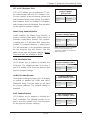
Ethernet Ports
An Intel® network controller is integrated into each of the serverboards to support
two Gigabit LAN ports (100/1000Base-T/1000BaseTX, RJ45 output).
Onboard Controllers/Ports
Onboard I/O backpanel ports on the serverboard include one COM port, a VGA port,
two USB ports, a dedicated IPMI LAN port and two Gigabit LAN (NIC) ports.
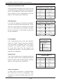
Graphics Controller
The H8QG6/i-F features an integrated Matrox G200eW graphics chip, which
includes 16 MB of DDR2 memory.
IPMI
IPMI (Intelligent Platform Management Interface) is a hardware-level interface
specifi cation that provides remote access, monitoring and administration for
Supermicro server platforms. IPMI allows server administrators to view a server’s
hardware status remotely, receive an alarm automatically if a failure occurs, and
power cycle a system that is non-responsive.
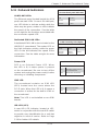
UIO
The H8QG6/i-F is a specially-designed serverboard that features Supermicro's
UIO (Universal I/O) technology. UIO serverboards have a PCI-Express x8 signals
that can support PCI-E cards or any one of several types of UIO card types to
add SAS ports, additional LAN ports, Infi niBand®, etc. to the serverboard. This
allows you to tailor the serverboard to your own needs.
Note: the server does not come with a UIO card installed.
Other Features
Other onboard features that promote system health include voltage monitors, auto-
switching voltage regulators, chassis and CPU overheat sensors, virus protection
and BIOS rescue.

1-4
A+ SERVER 2042G-TRF/6RF User's Manual
1-3 Server Chassis Features
The following is a general outline of the main features of the SC828TS+-R1400LPBP
server chassis.
System Power
The SC828TS+-R1400LPBP features a redundant (two separate power modules)
1400W high-effi ciency power supply with I
2
C. This power redundancy feature allows
you to replace a failed power supply without shutting down the system.
SAS/SATA Subsystem
The SC828TS+-R1400LPBP chassis was designed to support six hot-swappable
SAS or SATA hard drives.
Front Control Panel
The control panel on the A+ SERVER 2042G-TRF/6RF provides you with system
monitoring and control. LEDs indicate system power, HDD activity, network activity,
system overheat and power supply failure. A main power button and a system reset
button are also included. In addition, two USB ports and a COM port have been
incorporated into the front of the chassis for convenient access.
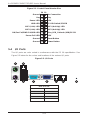
I/O Backplane
The SC828TS+-R1400LPBP is an ATX form factor chassis designed to be used in
a 2U rackmount confi guration. The I/O backplane includes one COM port, a VGA
port, two USB 2.0 ports, PS/2 mouse and keyboard ports, two gigabit Ethernet ports
and one dedicated Ethernet port for IPMI. Two x16, one x8 and one UIO or x8 low
profi le PCI-E expansion cards may be added to the system.
Cooling System
The SC828TS+-R1400LPBP chassis has an innovative cooling design that includes
six 8-cm heavy-duty hot-swap fans located in the middle section of the chassis. The
power supply module also includes a cooling fan. All chassis and power supply fans
operate continuously. An air shroud channels the airfl ow from the system fans to
effi ciently cool the processors and memory.

1-5
Chapter 1: Introduction
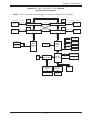
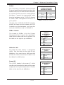
Figure 1-1. AMD SR5690/SP5100 Chipset:
System Block Diagram
Note: This is a general block diagram. Please see Chapter 5 for details.
G34-SOCKET #3
8x DIMM
8x DIMM
FWH
Keyboard/
Mouse
LPC SIO
W83527DHG-P
G34-SOCKET #2
VRM
G34-SOCKET #4
AMD
SR5690
#1
PCIE (X16)
H/W_MONITOR
W83795
HT Link
LPC BUS
PCIE (X8)
9_FAN_CONN.
VRM
6x PORTS
SATA_CONN
SATA
UIO SLOT
PCIE (X8)
HT Link
HT Link
VRM VRM
HT Link
16/16-1GHz
SLOT#2
PCIE (X16)
SLOT#3
PCIE_(X8)
HT Link
HT Link
8x DIMM
DDR3-1333/1066
USB
USB PORT
(0-6)
SLOT#4
PCIE_(X16)
LSI
SAS2 2008
PCIE (X4)
Intel
82576
PCIE (x4)
AMD
SP5100
Winbond
WPCM450
VGA
HT Link
16/16-1GHz
AMD
SR5670
#2
DDR3-1333/1066
DDR3-1333/1066
HT Link
PCIE (X8)
SLOT#1
PCIE_(X8)
CH A0,A1 B0,B1 C0,C1 D0,D1
8x DIMM
DDR3-1333/1066
CH A0,A1 B0,B1 C0,C1 D0,D1
G34-SOCKET #1

1-6
A+ SERVER 2042G-TRF/6RF User's Manual
1-4 Contacting Supermicro
Headquarters
Address: Super Micro Computer, Inc.
980 Rock Ave.
San Jose, CA 95131 U.S.A.
Tel: +1 (408) 503-8000
Fax: +1 (408) 503-8008
Email: [email protected] (General Information)
[email protected] (Technical Support)
Web Site: www.supermicro.com
Europe
Address: Super Micro Computer B.V.
Het Sterrenbeeld 28, 5215 ML
's-Hertogenbosch, The Netherlands
Tel: +31 (0) 73-6400390
Fax: +31 (0) 73-6416525
Email: [email protected] (General Information)
[email protected] (Technical Support)
[email protected] (Customer Support)
Asia-Pacifi c
Address: Super Micro Computer, Inc.
4F, No. 232-1, Liancheng Rd.
Chung-Ho 235, Taipei County
Taiwan, R.O.C.
Tel: +886-(2) 8226-3990
Fax: +886-(2) 8226-3991
Web Site: www.supermicro.com.tw
Technical Support:
Email: [email protected]
Tel: +886-(2) 8226-5990

Chapter 2: Server Installation
2-1
Chapter 2
Server Installation
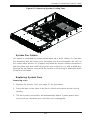
2-1 Overview
This chapter provides a quick setup checklist to get your 2042G-TRF/6RF up and
running. Following these steps in the order given should enable you to have the
system operational within a minimum amount of time. This quick setup assumes
that your system has come to you with the processors and memory preinstalled. If
your system is not already fully integrated with a serverboard, processors, system
memory etc., please turn to the chapter or section noted in each step for details on
installing specifi c components.
2-2 Unpacking the System
You should inspect the box the 2042G-TRF/6RF was shipped in and note if it was
damaged in any way. If the server itself shows damage you should fi le a damage
claim with the carrier who delivered it.
Decide on a suitable location for the rack unit that will hold the 2042G-TRF/6RF.
It should be situated in a clean, dust-free area that is well ventilated. Avoid areas
where heat, electrical noise and electromagnetic fi elds are generated. You will also
need it placed near a grounded power outlet. Be sure to read the Rack and Server
Precautions in the next section.
2-3 Preparing for Setup
The box the 2042G-TRF/6RF was shipped in should include two sets of rail
assemblies, two rail mounting brackets and the mounting screws you will need to
install the system into the rack. Follow the steps in the order given to complete
the installation process in a minimum amount of time. Please read this section in
its entirety before you begin the installation procedure outlined in the sections that
follow.

2-2
A+ SERVER 2042G-TRF/6RF User's Manual
Choosing a Setup Location
Leave enough clearance in front of the rack to enable you to open the front door •
completely (~25 inches) and approximately 30 inches of clearance in the back
of the rack to allow for suffi cient airfl ow and ease in servicing.
This product is for installation only in a Restricted Access Location (dedicated
•
equipment rooms, service closets and the like).
This product is not suitable for use with visual display work place devices •
acccording to §2 of the the German Ordinance for Work with Visual Display
Units.
Rack Precautions
Ensure that the leveling jacks on the bottom of the rack are fully extended to •
the fl oor with the full weight of the rack resting on them.
In single rack installation, stabilizers should be attached to the rack. In multiple •
rack installations, the racks should be coupled together.
Always make sure the rack is stable before extending a component from the •
rack.
You should extend only one component at a time - extending two or more si-•
multaneously may cause the rack to become unstable.
Server Precautions
Review the electrical and general safety precautions in Chapter 4.•
Determine the placement of each component in the rack • before you install the
rails.
Install the heaviest server components on the bottom of the rack fi rst, and then •
work up.
Use a regulating uninterruptible power supply (UPS) to protect the server from •
power surges, voltage spikes and to keep your system operating in case of a
power failure.
!
!
Warnings and Precautions!

Chapter 2: Server Installation
2-3
Allow the hot plug SAS drives and power supply modules to cool before touch-•
ing them.
Always keep the rack's front door and all panels and components on the servers •
closed when not servicing to maintain proper cooling.
Rack Mounting Considerations
Ambient Operating Temperature
If installed in a closed or multi-unit rack assembly, the ambient operating
temperature of the rack environment may be greater than the ambient temperature
of the room. Therefore, consideration should be given to installing the equipment
in an environment compatible with the manufacturer’s maximum rated ambient
temperature (Tmra).
Reduced Airfl ow
Equipment should be mounted into a rack so that the amount of airfl ow required
for safe operation is not compromised.
Mechanical Loading
Equipment should be mounted into a rack so that a hazardous condition does not
arise due to uneven mechanical loading.
Circuit Overloading
Consideration should be given to the connection of the equipment to the power
supply circuitry and the effect that any possible overloading of circuits might have
on overcurrent protection and power supply wiring. Appropriate consideration of
equipment nameplate ratings should be used when addressing this concern.
Reliable Ground
A reliable ground must be maintained at all times. To ensure this, the rack
itself should be grounded. Particular attention should be given to power supply
connections other than the direct connections to the branch circuit (i.e. the use of
power strips, etc.).

2-4
A+ SERVER 2042G-TRF/6RF User's Manual
2-4 Installing the System into a Rack
This section provides information on installing the 2042G-TRF/6RF into a rack unit
with the rack rails provided. If the system has already been mounted into a rack,
you can skip ahead to Sections 2-5 and 2-6. There are a variety of rack units on the
market, which may mean the assembly procedure will differ slightly. You should also
refer to the installation instructions that came with the rack unit you are using.
Identifying the Sections of the Rack Rails
You should have received two rack rail assemblies in the rack mounting kit. Each
assembly consists of two sections: an inner fi xed chassis rail that secures directly
to the server chassis and an outer fi xed rack rail that secures directly to the rack
itself. Two pairs of short brackets to be used on the front side of the outer rails are
also included.
Installing the Inner Rails
Both the left and right side inner rails have been pre-attached to the chassis.
Proceed to the next step.
Installing the Outer Rails
Begin by measuring the distance from the front rail to the rear rail of the rack. Attach
a short bracket to the front side of the right outer rail and a long bracket to the rear
side of the right outer rail. Adjust both the short and long brackets to the proper
distance so that the rail can fi t snugly into the rack. Secure the short bracket to the
front side of the outer rail with two M4 screws and the long bracket to the rear side
of the outer rail with three M4 screws. Repeat these steps for the left outer rail.
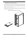
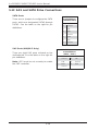
Locking Tabs
Both chassis rails have a locking tab, which serves two functions. The fi rst is to
lock the server into place when installed and pushed fully into the rack, which is
its normal position. Secondly, these tabs also lock the server in place when fully
extended from the rack. This prevents the server from coming completely out of
the rack when you pull it out for servicing.
Page is loading ...
Page is loading ...
Page is loading ...
Page is loading ...
Page is loading ...
Page is loading ...
Page is loading ...
Page is loading ...
Page is loading ...
Page is loading ...
Page is loading ...
Page is loading ...
Page is loading ...
Page is loading ...
Page is loading ...
Page is loading ...
Page is loading ...
Page is loading ...
Page is loading ...
Page is loading ...
Page is loading ...
Page is loading ...
Page is loading ...
Page is loading ...
Page is loading ...
Page is loading ...
Page is loading ...
Page is loading ...
Page is loading ...
Page is loading ...
Page is loading ...
Page is loading ...
Page is loading ...
Page is loading ...
Page is loading ...
Page is loading ...
Page is loading ...
Page is loading ...
Page is loading ...
Page is loading ...
Page is loading ...
Page is loading ...
Page is loading ...
Page is loading ...
Page is loading ...
Page is loading ...
Page is loading ...
Page is loading ...
Page is loading ...
Page is loading ...
Page is loading ...
Page is loading ...
Page is loading ...
Page is loading ...
Page is loading ...
Page is loading ...
Page is loading ...
Page is loading ...
Page is loading ...
Page is loading ...
Page is loading ...
Page is loading ...
Page is loading ...
Page is loading ...
Page is loading ...
Page is loading ...
Page is loading ...
Page is loading ...
Page is loading ...
Page is loading ...
Page is loading ...
Page is loading ...
Page is loading ...
Page is loading ...
-
 1
1
-
 2
2
-
 3
3
-
 4
4
-
 5
5
-
 6
6
-
 7
7
-
 8
8
-
 9
9
-
 10
10
-
 11
11
-
 12
12
-
 13
13
-
 14
14
-
 15
15
-
 16
16
-
 17
17
-
 18
18
-
 19
19
-
 20
20
-
 21
21
-
 22
22
-
 23
23
-
 24
24
-
 25
25
-
 26
26
-
 27
27
-
 28
28
-
 29
29
-
 30
30
-
 31
31
-
 32
32
-
 33
33
-
 34
34
-
 35
35
-
 36
36
-
 37
37
-
 38
38
-
 39
39
-
 40
40
-
 41
41
-
 42
42
-
 43
43
-
 44
44
-
 45
45
-
 46
46
-
 47
47
-
 48
48
-
 49
49
-
 50
50
-
 51
51
-
 52
52
-
 53
53
-
 54
54
-
 55
55
-
 56
56
-
 57
57
-
 58
58
-
 59
59
-
 60
60
-
 61
61
-
 62
62
-
 63
63
-
 64
64
-
 65
65
-
 66
66
-
 67
67
-
 68
68
-
 69
69
-
 70
70
-
 71
71
-
 72
72
-
 73
73
-
 74
74
-
 75
75
-
 76
76
-
 77
77
-
 78
78
-
 79
79
-
 80
80
-
 81
81
-
 82
82
-
 83
83
-
 84
84
-
 85
85
-
 86
86
-
 87
87
-
 88
88
-
 89
89
-
 90
90
-
 91
91
-
 92
92
-
 93
93
-
 94
94


SUPER MICRO Computer 2042G-6RF User manual
- Category
- Server barebones
- Type
- User manual
- This manual is also suitable for
Ask a question and I''ll find the answer in the document
Finding information in a document is now easier with AI
Related papers
-
SUPER MICRO Computer H8QGi+-F User manual
-
-
-
-
-
SUPER MICRO Computer H8DCT-HLN4F User manual
-
-
SUPER MICRO Computer H8SCM-F User manual
-
-
Other documents
-
Supermicro H8QG6+-F User manual
-
-
-
-
-
Supermicro H8DA6+-O User manual
-
Supermicro SuperChassis 837E26-RJBOD1 User manual
-
Supermicro MBD-H8SML-IF-O User manual
-
Gigabyte GS-SR101 System Installation Manual
-
In Win IW-RA100 + 300W User manual