Gefen GTB-HDMI1.3-444 User manual
- Category
- Video switches
- Type
- User manual
This manual is also suitable for
Gefen GTB-HDMI1.3-444 is a 4x4 Matrix for HDMI 1.3 that enables routing of high definition video and multichannel digital audio from any four HDMI sources to any four displays. The device supports resolutions up to 1080p@60Hz and 1920x1200@60Hz, and supports advanced audio formats such as Dolby TrueHD and DTS HD Master Audio. The matrix features auto-EDID management for rapid integration of sources and display devices, and supports the use of DVI sources and displays with an HDMI-to-DVI converter cable or adapter. Gefen GTB-HDMI1.
Gefen GTB-HDMI1.3-444 is a 4x4 Matrix for HDMI 1.3 that enables routing of high definition video and multichannel digital audio from any four HDMI sources to any four displays. The device supports resolutions up to 1080p@60Hz and 1920x1200@60Hz, and supports advanced audio formats such as Dolby TrueHD and DTS HD Master Audio. The matrix features auto-EDID management for rapid integration of sources and display devices, and supports the use of DVI sources and displays with an HDMI-to-DVI converter cable or adapter. Gefen GTB-HDMI1.


-
 1
1
-
 2
2
-
 3
3
-
 4
4
-
 5
5
-
 6
6
-
 7
7
-
 8
8
-
 9
9
-
 10
10
-
 11
11
-
 12
12
-
 13
13
-
 14
14
-
 15
15
-
 16
16
-
 17
17
-
 18
18
-
 19
19
-
 20
20
-
 21
21
-
 22
22
-
 23
23
-
 24
24
-
 25
25
-
 26
26
-
 27
27
-
 28
28


Gefen GTB-HDMI1.3-444 User manual
- Category
- Video switches
- Type
- User manual
- This manual is also suitable for
Gefen GTB-HDMI1.3-444 is a 4x4 Matrix for HDMI 1.3 that enables routing of high definition video and multichannel digital audio from any four HDMI sources to any four displays. The device supports resolutions up to 1080p@60Hz and 1920x1200@60Hz, and supports advanced audio formats such as Dolby TrueHD and DTS HD Master Audio. The matrix features auto-EDID management for rapid integration of sources and display devices, and supports the use of DVI sources and displays with an HDMI-to-DVI converter cable or adapter. Gefen GTB-HDMI1.
Ask a question and I''ll find the answer in the document
Finding information in a document is now easier with AI
Related papers
-
Gefen EXT-HDMI1-3-144 User manual
-
Gefen 4x4 Matrix for HDMI with FST and 3DTV Specification
-
-
-
-
-
-
-
-
Other documents
-
Satechi Satechi Aluminum Type-C Dual HDMI Adapter 4K 60Hz User guide
-
LogiLink HD0004 Datasheet
-
Xtech XTA-300 Datasheet
-
Novus 961+0439+000 Datasheet
-
Smart-AVI HDS-8P4K User manual
-
Key Digital KD4X4 User manual
-
Xantech HDMI4X4 User manual
-
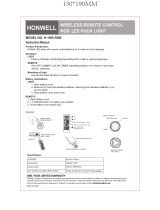 HONWELL Push Light RGB Lights Puck Lights User manual
-
-
Danfoss Electro Mechanical Room Thermostat Installation guide
