Emerson Transmitter User manual
- Category
- Measuring, testing & control
- Type
- User manual
This manual is also suitable for

Micro Motion
TM
Micro Motion
®
Model IFT9701 Transmitter
with Optional Display
Instruction Manual
Instruction Manual
P/N 3100572, Rev. E
March 2004


Micro Motion
®
Model IFT9701 Transmitter
with Optional Display
Instruction Manual
For online technical support, refer to the EXPERT
2
™ tool at
www.expert2.com. To speak to a customer service
representative, call the support center nearest you:
• In U.S.A., phone 1-800-522-MASS (1-800-522-6277)
• In Canada and Latin America, phone (303) 530-8400
• In Asia, phone (65) 6770-8155
• In the U.K., phone 0800 - 966 180 (toll-free)
• Outside the U.K., phone +31 (0) 318 495 670
©2004, Micro Motion, Inc. All rights reserved. Micro Motion is a registered trademark
of Micro Motion, Inc. The Micro Motion and Emerson logos are trademarks of
Emerson Electric Co. All other trademarks are property of their respective owners.


Model IFT9701 Transmitter Instruction Manual i
Contents
Chapter 1 Before You Begin . . . . . . . . . . . . . . . . . . . . . . . . . . . . . . . . . . . . . 1
1.1 About this manual . . . . . . . . . . . . . . . . . . . . . . . . . . . . . . . . . . . . . . . . . . . . . . . . . . . . 1
1.2 Safety . . . . . . . . . . . . . . . . . . . . . . . . . . . . . . . . . . . . . . . . . . . . . . . . . . . . . . . . . . . . . 1
1.3 European installations. . . . . . . . . . . . . . . . . . . . . . . . . . . . . . . . . . . . . . . . . . . . . . . . . 2
1.4 Definitions . . . . . . . . . . . . . . . . . . . . . . . . . . . . . . . . . . . . . . . . . . . . . . . . . . . . . . . . . . 2
1.5 Flowmeter components. . . . . . . . . . . . . . . . . . . . . . . . . . . . . . . . . . . . . . . . . . . . . . . . 2
Chapter 2 Getting Started. . . . . . . . . . . . . . . . . . . . . . . . . . . . . . . . . . . . . . . 5
2.1 Safety, reliability, accessibility . . . . . . . . . . . . . . . . . . . . . . . . . . . . . . . . . . . . . . . . . . . 5
2.1.1 Hazardous area . . . . . . . . . . . . . . . . . . . . . . . . . . . . . . . . . . . . . . . . . . . . . 5
2.1.2 Orientation and mounting . . . . . . . . . . . . . . . . . . . . . . . . . . . . . . . . . . . . . 6
2.1.3 Temperature, humidity, and vibration . . . . . . . . . . . . . . . . . . . . . . . . . . . . . 6
2.1.4 Visibility of tags . . . . . . . . . . . . . . . . . . . . . . . . . . . . . . . . . . . . . . . . . . . . . 7
2.2 Transmitters approved for ATEX Zone 1 . . . . . . . . . . . . . . . . . . . . . . . . . . . . . . . . . . . 7
2.3 Jumper settings. . . . . . . . . . . . . . . . . . . . . . . . . . . . . . . . . . . . . . . . . . . . . . . . . . . . . . 8
2.3.1 Security . . . . . . . . . . . . . . . . . . . . . . . . . . . . . . . . . . . . . . . . . . . . . . . . . . . 9
2.3.2 Fault output levels . . . . . . . . . . . . . . . . . . . . . . . . . . . . . . . . . . . . . . . . . . . 9
2.3.3 Re-installing the circuit board compartment cover. . . . . . . . . . . . . . . . . . 10
Chapter 3 Remotely Mounting the Transmitter . . . . . . . . . . . . . . . . . . . . . . . 11
3.1 Overview . . . . . . . . . . . . . . . . . . . . . . . . . . . . . . . . . . . . . . . . . . . . . . . . . . . . . . . . . . 11
3.2 Choosing the proper location . . . . . . . . . . . . . . . . . . . . . . . . . . . . . . . . . . . . . . . . . . 11
3.3 Mounting the transmitter . . . . . . . . . . . . . . . . . . . . . . . . . . . . . . . . . . . . . . . . . . . . . . 11
3.3.1 Guidelines for flat-surface mounting . . . . . . . . . . . . . . . . . . . . . . . . . . . . 11
3.3.2 Guidelines for pole mounting . . . . . . . . . . . . . . . . . . . . . . . . . . . . . . . . . . 11
3.4 Connecting the transmitter to the sensor . . . . . . . . . . . . . . . . . . . . . . . . . . . . . . . . . 14
3.4.1 Cable types . . . . . . . . . . . . . . . . . . . . . . . . . . . . . . . . . . . . . . . . . . . . . . . 14
3.4.2 Guidelines for conduit . . . . . . . . . . . . . . . . . . . . . . . . . . . . . . . . . . . . . . . 16
3.4.3 Guidelines for cable gland . . . . . . . . . . . . . . . . . . . . . . . . . . . . . . . . . . . . 16
3.4.4 Wiring connections to sensor. . . . . . . . . . . . . . . . . . . . . . . . . . . . . . . . . . 16
Chapter 4 Power Supply and Output Wiring . . . . . . . . . . . . . . . . . . . . . . . . . 19
4.1 Overview . . . . . . . . . . . . . . . . . . . . . . . . . . . . . . . . . . . . . . . . . . . . . . . . . . . . . . . . . . 19
4.2 Wiring guidelines. . . . . . . . . . . . . . . . . . . . . . . . . . . . . . . . . . . . . . . . . . . . . . . . . . . . 19
4.3 Connect power supply wiring . . . . . . . . . . . . . . . . . . . . . . . . . . . . . . . . . . . . . . . . . . 20
4.4 Connect output wiring . . . . . . . . . . . . . . . . . . . . . . . . . . . . . . . . . . . . . . . . . . . . . . . . 21
4.4.1 Milliamp output. . . . . . . . . . . . . . . . . . . . . . . . . . . . . . . . . . . . . . . . . . . . . 22
4.4.2 Milliamp output connected to Bell 202 multidrop network . . . . . . . . . . . . 23
4.4.3 Communication tools connected to milliamp output. . . . . . . . . . . . . . . . . 24
4.4.4 Pulse output. . . . . . . . . . . . . . . . . . . . . . . . . . . . . . . . . . . . . . . . . . . . . . . 25

ii Model IFT9701 Transmitter Instruction Manual
Contents continued
Chapter 5 Flowmeter Startup . . . . . . . . . . . . . . . . . . . . . . . . . . . . . . . . . . . 29
5.1 Overview . . . . . . . . . . . . . . . . . . . . . . . . . . . . . . . . . . . . . . . . . . . . . . . . . . . . . . . . . . 29
5.2 Customer service . . . . . . . . . . . . . . . . . . . . . . . . . . . . . . . . . . . . . . . . . . . . . . . . . . . 29
5.3 Startup procedures . . . . . . . . . . . . . . . . . . . . . . . . . . . . . . . . . . . . . . . . . . . . . . . . . . 29
5.4 Initialization . . . . . . . . . . . . . . . . . . . . . . . . . . . . . . . . . . . . . . . . . . . . . . . . . . . . . . . . 30
5.4.1 Diagnostic LED . . . . . . . . . . . . . . . . . . . . . . . . . . . . . . . . . . . . . . . . . . . . 30
5.4.2 Optional display . . . . . . . . . . . . . . . . . . . . . . . . . . . . . . . . . . . . . . . . . . . . 30
5.4.3 Startup mode. . . . . . . . . . . . . . . . . . . . . . . . . . . . . . . . . . . . . . . . . . . . . . 30
5.4.4 Operating mode. . . . . . . . . . . . . . . . . . . . . . . . . . . . . . . . . . . . . . . . . . . . 30
5.5 Flowmeter zeroing . . . . . . . . . . . . . . . . . . . . . . . . . . . . . . . . . . . . . . . . . . . . . . . . . . 31
5.5.1 Zeroing procedure . . . . . . . . . . . . . . . . . . . . . . . . . . . . . . . . . . . . . . . . . . 31
5.5.2 Diagnosing zero failure . . . . . . . . . . . . . . . . . . . . . . . . . . . . . . . . . . . . . . 32
5.6 Configuration, calibration, and characterization . . . . . . . . . . . . . . . . . . . . . . . . . . . . 32
5.7 Process measurement . . . . . . . . . . . . . . . . . . . . . . . . . . . . . . . . . . . . . . . . . . . . . . . 33
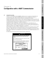
Chapter 6 Configuration with a HART Communicator . . . . . . . . . . . . . . . . . . . 35
6.1 Configuration overview . . . . . . . . . . . . . . . . . . . . . . . . . . . . . . . . . . . . . . . . . . . . . . . 35
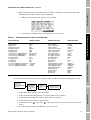
6.2 Configuration parameters . . . . . . . . . . . . . . . . . . . . . . . . . . . . . . . . . . . . . . . . . . . . . 36
6.2.1 HART tag. . . . . . . . . . . . . . . . . . . . . . . . . . . . . . . . . . . . . . . . . . . . . . . . . 36
6.2.2 Measurement units . . . . . . . . . . . . . . . . . . . . . . . . . . . . . . . . . . . . . . . . . 36
6.2.3 Flow cutoff . . . . . . . . . . . . . . . . . . . . . . . . . . . . . . . . . . . . . . . . . . . . . . . . 38
6.2.4 Damping . . . . . . . . . . . . . . . . . . . . . . . . . . . . . . . . . . . . . . . . . . . . . . . . . 38
6.2.5 Flow direction. . . . . . . . . . . . . . . . . . . . . . . . . . . . . . . . . . . . . . . . . . . . . . 39
6.2.6 Range values for milliamp output . . . . . . . . . . . . . . . . . . . . . . . . . . . . . . 40
6.2.7 Pulse output scaling . . . . . . . . . . . . . . . . . . . . . . . . . . . . . . . . . . . . . . . . 40
6.3 Calibration procedures . . . . . . . . . . . . . . . . . . . . . . . . . . . . . . . . . . . . . . . . . . . . . . . 41
6.3.1 Auto zero . . . . . . . . . . . . . . . . . . . . . . . . . . . . . . . . . . . . . . . . . . . . . . . . . 41
6.3.2 Flow calibration procedure. . . . . . . . . . . . . . . . . . . . . . . . . . . . . . . . . . . . 42
6.4 Characterization . . . . . . . . . . . . . . . . . . . . . . . . . . . . . . . . . . . . . . . . . . . . . . . . . . . . 44
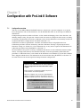
Chapter 7 Configuration with ProLink II Software . . . . . . . . . . . . . . . . . . . . . 45
7.1 Configuration overview . . . . . . . . . . . . . . . . . . . . . . . . . . . . . . . . . . . . . . . . . . . . . . . 45
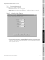
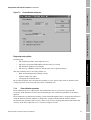
7.2 Configuration parameters . . . . . . . . . . . . . . . . . . . . . . . . . . . . . . . . . . . . . . . . . . . . . 46
7.2.1 HART tag. . . . . . . . . . . . . . . . . . . . . . . . . . . . . . . . . . . . . . . . . . . . . . . . . 46
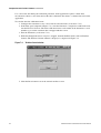
7.2.2 Process variable measurement . . . . . . . . . . . . . . . . . . . . . . . . . . . . . . . . 47
7.2.3 Output configuration . . . . . . . . . . . . . . . . . . . . . . . . . . . . . . . . . . . . . . . . 50
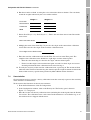
7.3 Calibration procedures . . . . . . . . . . . . . . . . . . . . . . . . . . . . . . . . . . . . . . . . . . . . . . . 51
7.3.1 Auto zero . . . . . . . . . . . . . . . . . . . . . . . . . . . . . . . . . . . . . . . . . . . . . . . . . 51
7.3.2 Flow calibration procedure. . . . . . . . . . . . . . . . . . . . . . . . . . . . . . . . . . . . 53
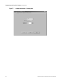
7.4 Characterization . . . . . . . . . . . . . . . . . . . . . . . . . . . . . . . . . . . . . . . . . . . . . . . . . . . . 55
Chapter 8 Troubleshooting. . . . . . . . . . . . . . . . . . . . . . . . . . . . . . . . . . . . . 57
8.1 Customer service . . . . . . . . . . . . . . . . . . . . . . . . . . . . . . . . . . . . . . . . . . . . . . . . . . . 57
8.2 General guidelines . . . . . . . . . . . . . . . . . . . . . . . . . . . . . . . . . . . . . . . . . . . . . . . . . . 57
8.3 Transmitter diagnostic tools . . . . . . . . . . . . . . . . . . . . . . . . . . . . . . . . . . . . . . . . . . . 57
8.3.1 Diagnostic LED . . . . . . . . . . . . . . . . . . . . . . . . . . . . . . . . . . . . . . . . . . . . 57
8.3.2 Optional LCD . . . . . . . . . . . . . . . . . . . . . . . . . . . . . . . . . . . . . . . . . . . . . . 58
8.3.3 Fault outputs . . . . . . . . . . . . . . . . . . . . . . . . . . . . . . . . . . . . . . . . . . . . . . 58
8.4 Power supply. . . . . . . . . . . . . . . . . . . . . . . . . . . . . . . . . . . . . . . . . . . . . . . . . . . . . . . 59
8.5 Wiring . . . . . . . . . . . . . . . . . . . . . . . . . . . . . . . . . . . . . . . . . . . . . . . . . . . . . . . . . . . . 60
8.6 Over range and sensor failure conditions . . . . . . . . . . . . . . . . . . . . . . . . . . . . . . . . . 61

Model IFT9701 Transmitter Instruction Manual iii
Contents continued
8.7 Slug flow . . . . . . . . . . . . . . . . . . . . . . . . . . . . . . . . . . . . . . . . . . . . . . . . . . . . . . . . . . 62
8.8 Transmitter failure . . . . . . . . . . . . . . . . . . . . . . . . . . . . . . . . . . . . . . . . . . . . . . . . . . . 63
8.9 Digital diagnostic messages . . . . . . . . . . . . . . . . . . . . . . . . . . . . . . . . . . . . . . . . . . . 63
Appendix A IFT9701 Specifications . . . . . . . . . . . . . . . . . . . . . . . . . . . . . . . . 65
A.1 Performance specifications . . . . . . . . . . . . . . . . . . . . . . . . . . . . . . . . . . . . . . . . . . . . 65
A.2 Functional specifications . . . . . . . . . . . . . . . . . . . . . . . . . . . . . . . . . . . . . . . . . . . . . . 65
A.2.1 Output signals . . . . . . . . . . . . . . . . . . . . . . . . . . . . . . . . . . . . . . . . . . . . . 65
A.2.2 Local display (optional) . . . . . . . . . . . . . . . . . . . . . . . . . . . . . . . . . . . . . . 66
A.2.3 Low-flow cutoff . . . . . . . . . . . . . . . . . . . . . . . . . . . . . . . . . . . . . . . . . . . . . 66
A.2.4 Slug-flow inhibit . . . . . . . . . . . . . . . . . . . . . . . . . . . . . . . . . . . . . . . . . . . . 66
A.2.5 Damping. . . . . . . . . . . . . . . . . . . . . . . . . . . . . . . . . . . . . . . . . . . . . . . . . . 66
A.2.6 Fault indication. . . . . . . . . . . . . . . . . . . . . . . . . . . . . . . . . . . . . . . . . . . . . 66
A.2.7 Output testing. . . . . . . . . . . . . . . . . . . . . . . . . . . . . . . . . . . . . . . . . . . . . . 66
A.2.8 Power supply options . . . . . . . . . . . . . . . . . . . . . . . . . . . . . . . . . . . . . . . . 66
A.3 Environmental limits . . . . . . . . . . . . . . . . . . . . . . . . . . . . . . . . . . . . . . . . . . . . . . . . . 67
A.3.1 Temperature. . . . . . . . . . . . . . . . . . . . . . . . . . . . . . . . . . . . . . . . . . . . . . . 67
A.3.2 Process fluid temperature limits. . . . . . . . . . . . . . . . . . . . . . . . . . . . . . . . 67
A.3.3 Humidity limits . . . . . . . . . . . . . . . . . . . . . . . . . . . . . . . . . . . . . . . . . . . . . 68
A.3.4 Vibration limits . . . . . . . . . . . . . . . . . . . . . . . . . . . . . . . . . . . . . . . . . . . . . 68
A.4 Density limits. . . . . . . . . . . . . . . . . . . . . . . . . . . . . . . . . . . . . . . . . . . . . . . . . . . . . . . 68
A.5 Environmental effects . . . . . . . . . . . . . . . . . . . . . . . . . . . . . . . . . . . . . . . . . . . . . . . . 68
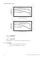
A.6 Ambient temperature effect on milliamp output. . . . . . . . . . . . . . . . . . . . . . . . . . . . . 69
A.7 Shipping weight. . . . . . . . . . . . . . . . . . . . . . . . . . . . . . . . . . . . . . . . . . . . . . . . . . . . . 69
A.8 Hazardous area classifications . . . . . . . . . . . . . . . . . . . . . . . . . . . . . . . . . . . . . . . . . 69
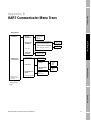
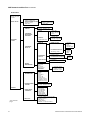
Appendix B HART Communicator Menu Trees . . . . . . . . . . . . . . . . . . . . . . . . . 71
Appendix C Installing the Optional Display . . . . . . . . . . . . . . . . . . . . . . . . . . . 73
Appendix D Return Policy. . . . . . . . . . . . . . . . . . . . . . . . . . . . . . . . . . . . . . . 75
D.1 General guidelines . . . . . . . . . . . . . . . . . . . . . . . . . . . . . . . . . . . . . . . . . . . . . . . . . . 75
D.2 New and unused equipment . . . . . . . . . . . . . . . . . . . . . . . . . . . . . . . . . . . . . . . . . . . 75
D.3 Used equipment . . . . . . . . . . . . . . . . . . . . . . . . . . . . . . . . . . . . . . . . . . . . . . . . . . . . 75
Index . . . . . . . . . . . . . . . . . . . . . . . . . . . . . . . . . . . . . . . . . . . . . . . . . . . . . 77

iv Model IFT9701 Transmitter Instruction Manual

Model IFT9701 Transmitter Instruction Manual 1
Getting Started Power Supply and Output WiringMounting the Remote TransmitterBefore You Begin
Chapter 1
Before You Begin
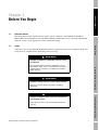
1.1 About this manual
This instruction manual explains how to install, start up, configure, and troubleshoot the Micro
Motion IFT9701 transmitter for use with Micro Motion Coriolis flow sensors. For more information
about the sensor, see the appropriate sensor instruction manual.
1.2 Safety
Safety messages are provided throughout this manual to protect personnel and equipment. Read each
safety message carefully before proceeding to the next step.
WARNING
Improper installation in a hazardous area can cause
an explosion.
For information about hazardous applications, refer to
Micro Motion ATEX, CSA, or UL installation instructions,
shipped with the transmitter or available from the Micro
Motion web site.
WARNING
Hazardous voltage can cause severe injury or death.
Make sure power is disconnected before installing
transmitter.
CAUTION
Improper installation could cause measurement error
or transmitter failure.
Follow all instructions to ensure transmitter will operate
correctly.

2 Model IFT9701 Transmitter Instruction Manual
Before You Begin continued
1.3 European installations
This Micro Motion product complies with all applicable European directives when properly installed
in accordance with the instructions in this manual. Refer to the EC declaration of conformity for
directives that apply to this product.
The EC declaration of conformity, with all applicable European directives, and the complete ATEX
Installation Drawings and Instructions are available on the internet at www.micromotion.com/atex or
through your local Micro Motion support center.
1.4 Definitions
• The term “sensor” refers to a Micro Motion sensor only.
• The term “flowmeter” refers to an IFT9701 transmitter and a sensor installed as a
flowmetering system.
1.5 Flowmeter components
The IFT9701 transmitter can be integrally mounted to a Micro Motion F-Series sensor, or remotely
mounted from an ELITE
®
, F-Series, Model D, or Model DL sensor.
The IFT9701 transmitter does not operate with Micro Motion T-Series, R-Series, or Model D600 or
DT sensors.
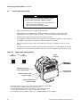
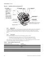
• If the transmitter is integrally mounted to the sensor, the flowmeter includes the components
shown in Figure 1-1.
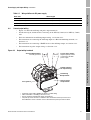
• If the transmitter will be remotely mounted from the sensor, the transmitter includes the
components shown in Figure 1-2.
The transmitter is available with an optional liquid crystal display (LCD), as shown in Figure 1-1 and
Figure 1-2, except for ATEX Zone 1 areas.
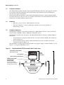
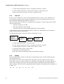
Figure 1-1 Integrally mounted IFT9701 transmitter with F-Series sensor
Model
IFT9701
transmitter
F-Series sensor
Flowmeter
Field wiring compartment
With optional LCD
Case ground
Sensor wiring compartment
4X M8 mounting bolt
4X lock washer
4X flat washer
To rotate transmitter:
remove, then re-install to
12 ft-lb (16 N-m) torque

Model IFT9701 Transmitter Instruction Manual 3
Before You Begin continued
Getting Started Power Supply and Output WiringMounting the Remote TransmitterBefore You Begin
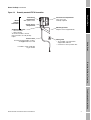
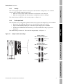
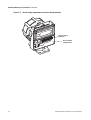
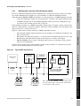
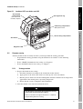
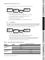
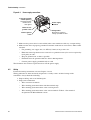
Figure 1-2 Remotely mounted IFT9701 transmitter
Model
IFT9701
transmitter
Field wiring
compartment
With optional LCD
Sensor wiring
compartment
4X M8 mounting bolt
•4X lock washer
• 4X flat washer
To rotate transmitter: remove,
then re-install to 12 ft-lb (16 Nm)
torque
Sensor cable
For minimum bend radius of cable,
see Figure 3-4, 3-5, or 3-6
If conduit is used, install drip
leg in conduit
Circuit board compartment
User access not
normally required
Mounting bracket
Requires 4 user-supplied bolts
Cable gland
• To assemble, see instructions
shipped with cable kit
• Connects to sensor junction box

4 Model IFT9701 Transmitter Instruction Manual

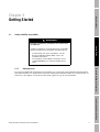
Model IFT9701 Transmitter Instruction Manual 5
Getting Started Power Supply and Output WiringMounting the Remote TransmitterBefore You Begin
Chapter 2
Getting Started
2.1 Safety, reliability, accessibility
2.1.1 Hazardous area
If you plan to mount the transmitter in a hazardous area, ensure that your equipment and installation
meet the hazardous area requirements. For more information about hazardous area classifications, see
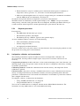
Section A.8. See Figure 2-1 for the location of the approvals tag on your transmitter.
WARNING
Improper installation in a hazardous area could cause
an explosion.
Install the transmitter in an environment that is compatible
with the hazardous area specified on the approvals tag.
• For intrinsically safe sensor installations, use this
document with Micro Motion ATEX, CSA, or UL
installation instructions.
• For hazardous area installations in Europe, refer to
standard EN 60079-14 if national standards do not
apply.

6 Model IFT9701 Transmitter Instruction Manual
Getting Started continued
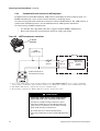
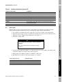
Figure 2-1 Location of approvals tag
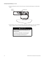
2.1.2 Orientation and mounting
Orient the transmitter so wiring compartments and conduit openings are easily accessible.
• To rotate the transmitter on the sensor manifold or the mounting bracket, use the four supplied
mounting bolt assemblies. Each bolt assembly includes one M8 bolt, one lock washer, and one
flat washer. Remove the bolt assemblies, rotate the transmitter, then reinstall the bolt
assemblies to 12 ft-lb (16 N-m) of torque.
• If the transmitter will be integrally mounted to a Micro Motion F-Series sensor, see the sensor
product data sheet for transmitter and sensor dimensions, and see the instruction manual that
was shipped with the sensor for information about flowmeter mounting and location.
• If the transmitter will be remotely mounted, use the supplied bolt assemblies to attach the
transmitter to the mounting bracket. Attach the bracket to a rigid, stable surface or instrument
pole that will not transfer excessive vibration into the transmitter. See Chapter 3 for more
information about remote mounting.
2.1.3 Temperature, humidity, and vibration
Install the transmitter according to specified limits:
• Ambient temperature
- without optional LCD: –22 to +131 °F (–30 to +55 °C)
- with optional LCD: 32 to 131 °F (0 to 55 °C)
• Humidity: 5 to 95% non-condensing
• Vibration: Meets IEC 68.2.6, 2 g
Hazardous area
approvals tag

Model IFT9701 Transmitter Instruction Manual 7
Getting Started continued
Getting Started Power Supply and Output WiringMounting the Remote TransmitterBefore You Begin
2.1.4 Visibility of tags
For personal and system safety, all tags attached to the transmitter housing must remain visible. Clean
or replace them as necessary.
2.2 Transmitters approved for ATEX Zone 1
If the transmitter carries an ATEX Zone 1 approval, wiring compartments are labeled as shown in
Figure 2-2.
• The sensor wiring compartment is rated EEx i (intrinsically safe), and may be opened at any
time. See Label 1 in Figure 2-2.
• The field wiring compartment is rated EEx e (increased safety), and should remain closed
when power is on. See Label 2 in Figure 2-2.
• The circuit board compartment is rated EEx d (flameproof), and should remain closed at all
times after the transmitter has been installed. If the transmitter is approved by ATEX as
flameproof, the compartment has a lockout device, shown in Figure 2-2. The lockout device
must be loosened and rotated before the compartment cover can be unscrewed.
WARNING
Explosion hazard
The circuit board compartment is rated EEx d
(flameproof), and should remain closed at all times after
the flowmeter has been installed.
To avoid risk of explosion in an explosive atmosphere:
• Read label that points to compartment cover before
accessing circuit board compartment. Figure 2-2
shows the location of the labels on the transmitter
housing.
• Shut off power, and wait at least 2 minutes before
removing EEx d (circuit board) compartment cover.
Figure 2-2 also identifies the EEx e (field wiring), EEx i
(sensor wiring), and EEx d (circuit board)
compartments.

8 Model IFT9701 Transmitter Instruction Manual
Getting Started continued
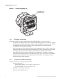
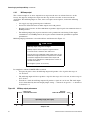
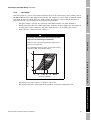
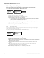
Figure 2-2 Compartment tags and lockout device
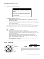
2.3 Jumper settings
Unless otherwise specified on the order, jumpers are set so the transmitter generates downscale fault
outputs and enables flowmeter configuration. If jumper settings need to be changed, the procedure
should be performed before the transmitter is installed.
• To access security and fault output jumpers, unscrew the circuit board compartment cover.
• If the transmitter is approved by ATEX as flameproof, the compartment has a lockout device.
See Figure 2-2. The lockout device must be loosened and rotated before the compartment
cover can be unscrewed.
CAUTION
Improper handling of transmitter components can
damage the transmitter.
• If a breaker bar is used for loosening the cover of the
circuit board compartment:
- Apply steady pressure to avoid chipping the paint on
the transmitter housing. Chipped paint can result in
corrosion of the housing. If paint becomes chipped,
repaint the housing.
- Do not apply too much pressure. Excessive torque
can damage the pipeline, transmitter, or sensor.
• To prevent electrostatic discharge, wear an anti-static
wrist strap while setting jumpers.
Field wiring
compartment
Rated EEx e
Lockout device
Loosen and rotate
before opening
circuit board
compartment
Label 1
Circuit board
compartment
Rated EEx d
Sensor wiring
compartment
Rated EEx i
Label 2

Model IFT9701 Transmitter Instruction Manual 9
Getting Started continued
Getting Started Power Supply and Output WiringMounting the Remote TransmitterBefore You Begin
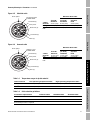
2.3.1 Security
The security jumper enables the user to write-protect the flowmeter configuration, so it cannot be
changed using a HART communication device:
• With the security jumper OFF, the flowmeter configuration can be changed.
• With the security jumper ON, the flowmeter configuration cannot be changed.
The default setting is OFF. To set the security jumper, see Figure 2-3.
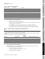
2.3.2 Fault output levels
The transmitter can be configured to produce downscale or upscale fault outputs. In a fault condition:
• Downscale: The milliamp output goes to 2 mA; the pulse output goes to 0 Hz.
• Upscale: The milliamp output goes to 22 mA; the pulse output goes to 7200 Hz.
• The diagnostic LED blinks ON four times per second, whether the setting is upscale or
downscale.
The default setting is downscale. To set the fault output jumper, see Figure 2-3.
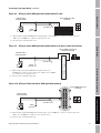
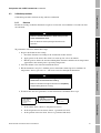
Figure 2-3 Jumper location and settings
Default settings
With standoff beneath jumpers
Optional settings
With standoff beneath jumpers
Downscale
faults
Security
OFF
Upscale
faults
Security
OFF
Upscale
faults
Security
ON
Downscale
faults
Security
ON

10 Model IFT9701 Transmitter Instruction Manual
Getting Started continued
2.3.3 Re-installing the circuit board compartment cover
To re-install the cover of the circuit board compartment:
1. Screw the cover back onto the housing.
2. Hand-tighten the cover until it seats on the O-ring.
3. If the circuit board compartment has a lockout device, as shown in Figure 2-2, rotate the clamp
into place and push it into the slot. Use a 4-mm (5/32-inch) Allen wrench to tighten the lockout
screw to 5 inch-pounds (0,56 N-m) of torque.

Getting Started Power Supply and Output WiringMounting the Remote TransmitterBefore You Begin
Model IFT9701 Transmitter Instruction Manual 11
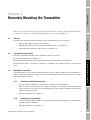
Chapter 3
Remotely Mounting the Transmitter
Note: The instructions in this chapter apply only if the transmitter will be remotely mounted from the
sensor. If the transmitter is integrally mounted to the sensor, proceed to Chapter 4.
3.1 Overview
To mount the transmitter remotely from the sensor, the following steps are required:
• Choosing the proper location (see Section 3.2)
• Mounting the sensor on a flat surface or instrument pole (see Section 3.3)
• Connecting the transmitter to the sensor (see Section 3.4)
3.2 Choosing the proper location
Install the transmitter according to the conditions stated in Section 2.1.
For mounting dimensions, see Figure 3-1.
Total length of cable from sensor to transmitter must not exceed 1000 feet (300 meters).
For bend radii of cables, see Figure 3-4, Figure 3-5, or Figure 3-6, according to the type of cable to be
used.
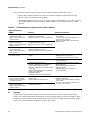
3.3 Mounting the transmitter
A transmitter that is to be remotely mounted from the sensor is shipped with an L-shaped mounting
bracket. Attach the bracket to a rigid, stable surface or instrument pole that will not transfer excessive
vibration into the transmitter.
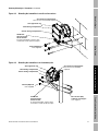
3.3.1 Guidelines for flat-surface mounting
• Use four 5/16-inch (M8) nuts (not included), suitable for the environment.
• Do not secure bolts to separate beams, girders, wall studs, etc., which can move independently.
• To prevent unnecessary stress on the mounting bracket, use washers to shim the bracket if the
mounting surface is not flat.
• For more information, see Figure 3-2.
3.3.2 Guidelines for pole mounting
• Use two 5/16-inch (M8) U-bolts for 2-inch pipe, and four 5/16-inch (M8) nuts (not included),
suitable for the environment.
• For more information, see Figure 3-3.

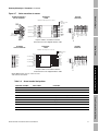
12 Model IFT9701 Transmitter Instruction Manual
Remotely Mounting the Transmitter continued
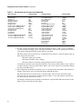
Figure 3-1 Installation dimensions for remote mounting
Dimensions in
inches
(mm)
5 3/4
(146)
2 13/16
(71)
61/64
(24)
4X
Ø 25/64
(10)
2 13/16
(71)
4 1/4
(108)
9 43/64
(245)
4 53/64
(122)
6 17/64
(159)
For minimum bend radii
of cable, see Figure 3-4,
Figure 3-5, or Figure 3-6
7 1/64
(178)
2X 5 57/64
(150)
1 3/4
(44)
(1)
4 1/4
(107)
19/32
(15)
3/4″–14 NPT
or M20 X 1.5
for power wiring
3/4″–14 NPT
or M20 X 1.5
for output wiring
Field wiring
compartment
3/4″–14 NPT
gland for sensor wiring
1/2
(13)
Character
height
(1)If transmitter is ordered without display,
dimension is 1 3/8 (35).
Page is loading ...
Page is loading ...
Page is loading ...
Page is loading ...
Page is loading ...
Page is loading ...
Page is loading ...
Page is loading ...
Page is loading ...
Page is loading ...
Page is loading ...
Page is loading ...
Page is loading ...
Page is loading ...
Page is loading ...
Page is loading ...
Page is loading ...
Page is loading ...
Page is loading ...
Page is loading ...
Page is loading ...
Page is loading ...
Page is loading ...
Page is loading ...
Page is loading ...
Page is loading ...
Page is loading ...
Page is loading ...
Page is loading ...
Page is loading ...
Page is loading ...
Page is loading ...
Page is loading ...
Page is loading ...
Page is loading ...
Page is loading ...
Page is loading ...
Page is loading ...
Page is loading ...
Page is loading ...
Page is loading ...
Page is loading ...
Page is loading ...
Page is loading ...
Page is loading ...
Page is loading ...
Page is loading ...
Page is loading ...
Page is loading ...
Page is loading ...
Page is loading ...
Page is loading ...
Page is loading ...
Page is loading ...
Page is loading ...
Page is loading ...
Page is loading ...
Page is loading ...
Page is loading ...
Page is loading ...
Page is loading ...
Page is loading ...
Page is loading ...
Page is loading ...
Page is loading ...
Page is loading ...
Page is loading ...
Page is loading ...
Page is loading ...
Page is loading ...
-
 1
1
-
 2
2
-
 3
3
-
 4
4
-
 5
5
-
 6
6
-
 7
7
-
 8
8
-
 9
9
-
 10
10
-
 11
11
-
 12
12
-
 13
13
-
 14
14
-
 15
15
-
 16
16
-
 17
17
-
 18
18
-
 19
19
-
 20
20
-
 21
21
-
 22
22
-
 23
23
-
 24
24
-
 25
25
-
 26
26
-
 27
27
-
 28
28
-
 29
29
-
 30
30
-
 31
31
-
 32
32
-
 33
33
-
 34
34
-
 35
35
-
 36
36
-
 37
37
-
 38
38
-
 39
39
-
 40
40
-
 41
41
-
 42
42
-
 43
43
-
 44
44
-
 45
45
-
 46
46
-
 47
47
-
 48
48
-
 49
49
-
 50
50
-
 51
51
-
 52
52
-
 53
53
-
 54
54
-
 55
55
-
 56
56
-
 57
57
-
 58
58
-
 59
59
-
 60
60
-
 61
61
-
 62
62
-
 63
63
-
 64
64
-
 65
65
-
 66
66
-
 67
67
-
 68
68
-
 69
69
-
 70
70
-
 71
71
-
 72
72
-
 73
73
-
 74
74
-
 75
75
-
 76
76
-
 77
77
-
 78
78
-
 79
79
-
 80
80
-
 81
81
-
 82
82
-
 83
83
-
 84
84
-
 85
85
-
 86
86
-
 87
87
-
 88
88
-
 89
89
-
 90
90


Emerson Transmitter User manual
- Category
- Measuring, testing & control
- Type
- User manual
- This manual is also suitable for
Ask a question and I''ll find the answer in the document
Finding information in a document is now easier with AI
Related papers
-
Emerson MICRO MOTION 2700 User manual
-
Micro Motion Micro Motion 2500 Owner's manual
-
-
-
-
-
-
-
-
Other documents
-
-
-
-
-
-
-
-
Milwaukee 58-01-0560 User manual
-
-