Page is loading ...

Conventions
WARNINGS – To help avoid personal injury
Important Notes/Cautions – from the factory
Sanitation Requirements
1. Connectawaterlinefromyourfacilitytothe1/4”arewaterinletttingofthevalve,behindthe
machine.Watervolumegoingtothemachineshouldbestable.Usetubingsizedsufcientlyto
provideaminimumowrateofonegallonperminute.
2. Plugthepowercordintoanelectricaloutletratedat20A.
3. Switchonthetoggleswitch,behindtheunit,thatrunspowertothecomponentsinthemachine.
Thelights(displaywindowandrowofbuttons)onthefrontdoorwillactivateandtheheating
tankwillstarttoll.
4. Waterintheheatingtankwillrequireaboutonehourtoreachoperatingtemperature(factory
settingof190°F).AtthistimetheLCDwilldisplay“READYTODISPENSE”.
5. Removeandllthecanisterswithpowderedproduct.
Service Manual – Expressions Multi-avor
Thisapplianceisdesignedforcommercialuse.Anyservicingotherthancleaningandmaintenance
shouldbeperformedbyanauthorizedWilburCurtisservicecenter.
• DoNOTimmersetheunitinwateroranyotherliquid
• Toreducetheriskofreorelectricshock,doNOTopentoppanel.Nouserserviceable
partsinside.Repairshouldbedoneonlybyauthorizedservicepersonnel.
• Keephandsandotheritemsawayfromhotpartsofunitduringoperation.
• Nevercleanwithscouringpowdersorharshimplements.
Your Curtis G3 System is Factory Pre-Set and Ready to Go, Right from the Carton.
FollowingaretheFactorySettingsforyourExpressionsMulti-avorBeverageSystem:
• Tank Temperature = 190°F
• Dispensing Mode Set for Manual Dispense
GenerallytherewillneverbeareasontochangeyourG3programming.However,shouldyouneed
tomakeslightadjustmentstomeetyourdispensingneeds,programminginstructionsareprovided
laterinthismanual.
SystemRequirements:
• Water Source20–90PSI(MinimumFlowRateof1GPM)
• Electrical:Seeattachedschematicforstandardmodelorvisitwww.wilburcurtis.comfor
yourmodel.
Equipmenttobeinstalledtocomplywithapplicablefederal,state,orlocalplumbing/electricalcodes
havingjurisdiction.
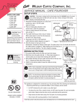
SETUP STEPS
Theunitshouldbelevel(lefttorightandfronttoback),locatedonasolidcountertop.
Connectawaterlinefromthewaterltertothebrewer.
NOTE: Some type of water ltration device must be used to maintain a trouble-free operation. (In
areas with extremely hard water, we suggest that a sedimentary and taste & odor lter be installed.)
This will prolong the life of your dispensing system and enhance cappuccino product quality.
Wi l b u r Cu r t i s Co m p a n y , in C .
Important Safeguards/Conventions
CAUTION: DO NOT
connect this unit to
hot water. Inlet valve
not rated for hot water.
CAUTION: Use this
setup procedure
before attempting
to use this appliance. Failure
to follow the instructions can
result in injury or the voiding
of the warranty.
WARNING, HOT
LIQUID
WILBUR CURTIS COMPANY
Montebello, CA 90640
ISO 9001 REGISTERED
WARNING HOT
LIQUID, Scalding
may occur. Avoid
splashing.
1
Models Included:
■ EXPR
NSF International requires the following water connection:
1. A quick disconnect or additional coiled tubing (at least 2x the depth of the unit) so that
the machine can be moved for cleaning underneath.
2. This equipment is to be installed with adequate back ow protection to comply with ap-
plicable federal, state and local codes..
3. Water pipe connections and xtures directly connected to a potable water supply shall
be sized, installed and maintained in accordance with federal, state, and local codes.

FILL CANISTERS DAILY
1.Openthefrontdoortoaccesscanisters.
2.Rotatethepowderdeliveryelbowsupward.
3.Thecanistersmustberemovedfromtheunitforlling.Toremove,liftcanisterslightlywhilepullingbackoffthecanistertray.
4.Rellallcanisterswithproduct,thenrepositionthemonthemachine,aligningthegearsocketwiththegearonthemotorshaft.
5.Rotatethepowderdeliveryelbowsdownwardandclosethefrontdoor.
CAUTION - Do not use cleansers, liquid bleach, powders or any other substance containing chlorine. These products
promote corrosion and will pit the stainless steel. THE USE OF THESE PRODUCTS WILL VOID YOUR WARRANTY.
2
Cleaning the Curtis Multi-avor Beverage Dispenser
Operation Instructions
1.Placeyourcupunderthespout.
2.Decideonaavorandpressthedispensingbuttonforthisavor.Hotcappuccinodrinkwillow
fromthedispensingspoutintothecup.
3.Besuretoreleasethebuttonwhenthecupisabout¾full.Hotliquidcontinuestoowforabout
foursecondsafterreleasing.Thisistoclearthewhipperchamberofremainingproduct.
I. EVERY 3 - 4 HOURS OR MORE OFTEN IF NECESSARY
A. MakesurepowerisON.
B. Catchrinsewater.Placeacontainerontopofthedriptray,belowthedispensingspout.
C. LocatetheWASHbuttononthefrontcontrolpanel.Rinseeachavorbypressingand
holdingtheWASHbutton,atthesametimepressingoneofthePUSHdispensing
buttonsonthecontrolpanel.ContinueholdingWASHuntiltherinsewaterrunsclear.
D Disposeofrinsewatercontainerandit’scontents.
II. DAILY Refertothedailycleaninginstructionsontheinsideofthefrontdoor,seeillustration
below.
A. SwitchOFFtheunitatthepowertoggleswitch,locatedbehindtheunit.
B. Wipeallexteriorsurfaceswithadampenedcloth,removinganyspills,residueordust
from the unit.
C. Removethedripdrawerandlouveredscreen;thenwashoutitscontents.Forhardto
cleandeposits,useamild,non-abrasivedetergent.Rinsewithwater.
D. Wipeandcleanthedispensingareawithamilddetergentcleaner.
E.SwitchONtheunitatthetoggleswitch.
III. WEEKLY OR MORE OFTEN IF NECESSARY
A. Openthefrontdoortolocatethewhipperassembly.Disassembleandclean
thewhipperchamberpartswithwarmwaterandamilddetergent.
1. Oneatatime,lifteachcanisterslightlyandrotatethedeliveryelbowto
pointupward.
2. Removethemanifold,pullingbackonthespouttoreleaseitfromthe
alcove,(illustrationright).
3. Removetheuppermixingcup.Pullcupforward,twisttotheleftandliftit
toseparatetheuppermixingcupfromthelowermixingcup.
4. Toremovethelowermixingcup,pullmixingcupupandforwardtofreeit
fromthehotwaterinlettting.
5. Removethedispensingnozzlefromthewhipperchamber.Cleanthe
insideusinganarrowbrush.
6. Removethewhipperchamber.

a.Takeholdofthewhipperchamberwithonehandwhileholdingthewhippermountingplatewiththeother.Turnitclock
wisetofreeitfromthemountingplate.
b.Removewhipperchamberfromtheunitandcleanitthoroughly.
7. Pullthewhipperpropellerfromthemotorshaftandcleanit.
IMPORTANT - When replacing the propeller, make sure the propeller is properly aligned and seated
on the motor shaft. Some propellers may have an indicator; a wide, at surface to lineup with the
at on the shaft (illustration, right).
The newer propellers have an embossed D’, indicating how to position the propeller on the motor shaft.
Failure to push the propeller in all the way will cause the propeller to fuse with the whipper chamber. This
condition will not be covered under warranty.
8. Cleanthemountingplate.
a. Cleantheshaftwithaclothandmilddetergentbeforeremovingmountingplate.
b. Twistthemountingplateclockwiseandpullitfromthemotorshaft.
c. Cleantheareabehindthemountingplate.
d. Cleanthewaterinlettting.
e. Lubricatethecentersealofthemountingplatebeforereinstalling.
9.Washandrinseallpartsthatwereremovedforcleaning.
9. Allowpartstodry.Assemblethewhipperassemblyandclosethefrontdoor.
10.Theunitisreadyforuse.
IMPORTANT-Donotremovepillarstotakeoffmountingplate.
3
Steps to Programming
Your Curtis Generation 3 cappuccino dispenser is Factory Pre-Set for Optimum Performance.
Entering the Programing Menus
PressandholdSTOP/WASHforaboutten[10]secondsuntildisplayreadsProgram Menus(SeeIllustration).Releasebutton.
Scrollthroughmenuusing→ or ←controlbutton.SelectmenuitemsyouwishtoenterwiththeStop/Washbutton.

4
Program Menus
Manual Dispense (Factory Default)
Pressor►togotoManual Dispense Select.
PresstogotoManualDispenseSelectStation.
Choosethestationandpress,thedisplaywillreadSavingComplete!Toselectanotherstationformanualdispense,presstogo
toManualDispenseSelectStationorpress►tocontinuetothenextmenu.
Dispense By Time
ThenextscreenisDispense By Time◄Select►.
Before making this adjustment and to avoid guessing the time, run a stop watch on the time it takes to ll a cup in the
Manual Dispense mode. Use the timed results to determine your Dispense By Time setting.
Pressandallstationindicatorlightswillash.SelectastationtoprogrambypressingthePUSHbuttononyourchosenstation.
Screenwillshowthecurrentsetting(from0.0to30.0seconds,in½secondincrements).Pressto►increasethetimeor◄to
decrease.Toset,pressandyouwillexitbacktoDispense by Timescreen.Continuewithadditionalselectionsorpress►to
continuetothenextmenu.
Temperature (Factory set at 190°F)
PressandscreenwillshowTank Temperature.Temperatureisprogrammablefrom170°Fto204°Fin2-degreeincrements.
Press◄or►togoupordownindegrees.Selectdesiredtemperatureandthen toset.Press►tocontinuetothenext
menu.
Powder % Ratio
PressandthescreenwilldisplayPowder Ratio Select Station.ThisisshownasA,B,C,DandE,correspondingtocanisters,
arrangedlefttoright(whenfacingthemachine),startingwithA.Pressdesiredstation.Powderratioforeachcanisteravorispro-
grammablefrom0%to100%,in5%increments.
Press◄ or ► toincreaseordecreaseratioandthenpresstoset.Press►tocontinuetothenextcanister.AfterEthescreen
returnstoPowderRatio.Press►tocontinuetothenextmenu.
Service Call (Phone number)
Presstodisplaynumberandpresschangenumberor ►tomoveplacesandEXtoexitwhencompleteThisnumberwillbe
displayedduringaHeatingsystemSENSORERRORoraWATERERROR.Press►tocontinuetothenextmenu.
Banner Name
Presstodisplayletters,presstochangelettersor ►tomoveplacesandEXtoexitwhencomplete.
Thisfeatureallowsupto14letterstobeprogrammedforcompanynameorregionalname.ProgrammingallblanksdisablesBan-
nerName.Ifprogrammed,BannerNameisdisplayedevery5sec.onandoff.Press►tocontinuetothenextmenu.
Exit
Presstoselect,exitsprogrammodeandreturnsunittooperation.
CONFIGURATION OF CANISTERS
MODEL
ONE
10 LB. CANISTER
P/N CA-1113-06R
ULTRA-SLIM
P/N CA-1142-06
FOUR
EXPR
A
B
C
D
E

* Suggested Parts to Stock
5
Illustrated Parts List
PANEL, LEFT SIDE EXPR
DOOR, COMPLETE
FILM, GENERIC EXPR
LAMP COMPLETE, W/5K BULB
KIT, UCM & SMART CARD & OVERLAY
LABEL, UCM PANEL
COVER, ALCOVE PLASTIC EXPR
CAPACITOR, X2 ALL ADS MODELS
CONTROL, POWER MODULE (NOT SHOWN)
FAN, EXTRACT (NOT SHOWN)
O-RING, DUMP VLV WC-880E (NOT SHOWN)
KIT, TANK LID ROUND
KIT, WATER LEVEL PROBE
KIT, RPL DUMP VALVE FOR WC-880E
HEATING ELEMENT, 1.45KW W/JAMNUTS
SENSOR, TEMPERATURE TANK
THERMOSTAT, MNL RESET 120/240V 25A
SWITCH, TOGGLE NON LIT 25A 120/240V
COVER, DRIP TRAY PLASTIC PCGT-3
DRIP TRAY, PLASTIC PCGT-3
SCREEN, DRIP TRAY PCGT3
CANISTER, ASSY ULTRA SLIM
CANISTER ASSY, 10LB RIGHT PCGTs
FITTING, BULKHEAD WATER
CONNECTOR, ORIFICE WATER PCGT
ELBOW, PC/CK/HC
ELBOW, CANISTER RIGHT
ELBOW, CANISTER LEFT
STEAM TRAP
BOWL, MIXING
MANIFOLD 3 IN 1 BARISTA
LID, CANISTER, ULTRA SLIM
1
2
3
4
5
6
7
8
9
10
11*
12
13
14
15
16
17
18
19
20
21
22
22A
23
24
25
25A
25B
26
27
28
29
WC-58223
WC-58232
CA-1143
CA-1127 *
WC-37298*
WC-39608
CA-1098-102
WC-8591 *
WC- 796
WC-37123
CA-1039*
WC-37008
WC-37278*
WC-3734 *
WC- 917-04*
WC-1438-101*
WC- 523 *
WC- 102 *
CA-1100-101
CA-1099-101
WC-68131-101
CA-1142-06
CA-1113-06R
CA-1011-05
CA-1095
CA-1026-03
CA-1026-06
CA-1026-07
CA-1005-03 *
CA-1009-03 *
CA-1152 *
CA-1142
Item Nº Part Nº Description
LID, CANISTER, 10LB PCGT’s
ADAPTOR, EXTRTR FAN HOSE (NOT SHWN)
KIT, SOCKET GEAR PC/CK/HC
EXTENSION, GEAR MOTOR SHAFT
MOTOR, WHIPPER
RING, MOTOR SHAFT PLASTIC
KIT, WHIPPER PLATE (W/SEAL) 3/PKG
KIT, PROPLR OFFSET BLADES PCGT PKG6
WHIPPER CHAMBER
PILLAR, LOCATION BLACK
KIT, GEAR MOTOR, CORK BRAKE PCGT
GEAR, PLASTIC USE ON CA-1013’s
KIT, INLET VALVE REPAIR USE ON WC-826L
COMPOUND, SILICONE 5 OZ TUBE
LABEL, CLEAN ENG/SPNSH (NOT SHOWN)
VALVE, INLET
HEAT SINK ASSEMBLY (NOT SHOWN)
TUBE, 5/16” ID X 1/8”w SILICONE
HOSE, EXTRACTOR FAN 23” LONG
HEATING TANK, COMPLETE EXPR
COVER, DUMP VALVE PC-3GT
CANISTER TRAY, ASSY
LAMP, 30W 5K CIRCULAR
LATCH ASSY, DOOR SIDE MOUNT
LEG, 3/8”-16 STD SCREW BUMPER
LEG, GUIDE 3/8”-16 STUD SCREW
O-RING, ½” I.D. (NOT SHOWN)
GUARD, SHOCK HEATING ELEMENT
INSULATION, WRAP PCGT
PANEL, RIGHT SIDE
BUSHING, CONICAL .583 ID x .945 OD x .945 L
29A
30
31
32
33
34
35
36
37
38
39
40
41
42
43
44
45
46
47
48
49
50
51
52
53
54
55
56
57
58
59
WC-5664-05
WC-66047
WC-37054
WC-58229
WC-3739 *
WC-43791 *
WC-37118 *
CA-1008-07K *
CA-1006-06 *
CA-1024-05
WC-37174 *
CA-1036 *
WC-3765L *
WC-5231 *
WC-38460
WC- 826L *
WC-8556 *
WC-5310 *
CA-1030-23
WC-62043
WC-58121
WC-58228
CA-1123
CA-1135
WC-3503
WC-3518
WC-4320
WC-4394
WC-3689
WC-58224
WC-2627
Item Nº Part Nº Description
Illustrated Parts List – Detail Bubbles
16
42
41
37
38
34
35
36
Before mounting a whipper
plate, place a dab of food
grade lubricant in the rear
hole of the seal.
Shaft seals should be
replaced with the groved
side facing outward.
Place a dab of food
grade lubricant in the
rear hole of the seal,
as shown below.

39
32
40
6
1
4
3
5
6
12
13
14
57
56
15
17
28
7
53
19
21
44
18
8
54
20
49
58
51
52
50
Illustrated Parts List
2
46
47
31
33
24
23
25
26
27
48
29
29A
22
22A

Electrical Diagram
7
PHASE:
WIRES:
AMPERAGE:
WATTAGE:
HERTZ:
VOLTAGE:
MODEL NUMBER:
REVISION:
PART NUMBER:
TITLE:
NEXT ASSEMBLY :
1PH
2W+G
SEE TABLE
50/60HZ
SEE TABLE
120VAC
FINAL
SEE ELECTRICAL TABLE
NC
LD-EXPR-10
LADDER DIAGRAM
TANK
WATER
8
7
6
5
2
4
3
1
12
11
10
9
15
16
14
13
12
11
10
6
8
7
5
4
3
2
1
3
6
8
9
7
5
4
2
1
3
1
2
4
WATER LEVEL
TEMP. SENSOR
PROBE ASSY
1GPM INLET VALV E
GEAR MOTOR #1
120V, 60W
120V, 12W
120V, 10W
DUMP VALVE #1
WHIPPER MOTOR #1
120V, 66W
GEAR MOTOR #2
120V, 66W
DUMP VALVE #2
120V, 12W
WHIPPER MOTOR #2
120V, 60W
GEAR MOTOR #3
120V, 66W
GEAR MOTOR #4
120V, 66W
DUMP VALVE #3
120V, 12W
GEAR MOTOR #5
120V, 66W
120V, 60W
WHIPPER MOTOR #3
CHASSIS GROUND
( Vdd+12v)
(Vss -)
(GROUND)
(UCM DATA )
CHASSIS GROUND
4-WIRE COMMUNICATION CABLE
UCM MODULE & LAMP
120VAC SUPPLY FOR
(UCM DATA )
(GROUND)
(Vdd+12v)
( Vss-)
WHT
BLK
2-WIRE CABLE
GROUND
GROUND
BLK (Vdd+5v)
RED (SPS DATA )
WHT (GRND)
GROUND
3-WIRE CABLE
(WHT)
WHT
ORG
(WHT)
WHT
VIO
VIO
WHT
WHT
WHT
WHT
WHT
GRN
WHT
WHT
WHT
(BRN)
(BLU)
WHT
WHT
WHT
WHT
YEL
GRN
GRN
GRN
GRN
GRN
GRN
GRN
GRN
GRN
GRN
GRN
WHT
BLK
WHT
WHT
WHT
WHT
WHT
WHT
BLK
GRN
WHT
16 PIN CONNECTOR
12 PIN CONNECTOR
BLK
BLK
BLK
WHT
(GRN)
(BRN)
(BLU)
(GRN)
(BRN)
(BLU)
(GRN)
BRNBRN
STP GRN
STP BRN
STP VIO
YEL
STP YEL
YEL
STP YEL
STP BLU
REDRED
STP RED
STP GRY
STP GRY
VIO
BLU
BRN
BLK
ORG
BLU
BRN
BLK
ORG
STP VIO
TRIAC PIN ASSIGNMENTS
CAPACITOR
EXTRACTOR FAN
HEATSINK
ASSY
TRIAC
120V, 60Hz 15W
T°
GATE
ANODE2
A2
G
ANODE1
A1
G5
W3
G4
G3
W2
G2
G1
W1
UNIVERSAL CONTROL
MODULE(UCM)
FRONT DOOR
BALLAST
30W LIGHT
2.
UNIVERSAL POWER MODULE(UPM)
POWER CORD
POWER
SUPPLY
120V/60Hz
(GRN)
(BLK)
(WHT)
THERMOSTAT
MANUAL RESET
SPST 25A 125/250V
BLK #14
WHT
WHTBLK
120Vac
A2
BLK
A1
G
BLK #14
RED #14
1
WHT #14
2
TOGGLE SWITCH
SET @ 220ºF
SPST
12
HEATING
ELEMENT
SMART CARD MODULE(SPS)
4-PIN CONNECTOR
8-PIN CONNECTOR
ELEMENT
(WATTS)(AMP.)(WATTS)(WATTS) (AMP.)
(SC)EXPR10
1800 15 1450
MACHINE
TOTAL
POWER
CANADIAN MODELS
ELECTRICAL RATING TABLE
US MODELS
TOTAL
POWER
TOTAL
CURRENT CURRENT
TOTALHEATING
1. ALL WIRES SHALL BE 22 AWG TEFLON.
NOTES: UNLESS OTHERWISE SPECIFIED
2. INSTALL GROUND ON TANK BEFORE CHASSIS.

WILBUR CURTIS CO., INC.
6913 Acco St., Montebello, CA 90640-5403 USA
Phone: 800/421-6150 Fax: 323-837-2410
Technical Support Phone: 800/995-0417 (M-F 5:30A - 4:00P PST) E-Mail: [email protected]
Web Site: www.wilburcurtis.com
8
Printed in U.S.A. 12/08 F-3570 Rev A
Product Warranty Information
The Wilbur Curtis Company certies that its products are free from defects in material and workmanship under normal use. The following limited
warranties and conditions apply:
3 Years, Parts and Labor, from Original Date of Purchase on digital control boards.
2 Years, Parts, from Original Date of Purchase on all other electrical components, ttings and tubing.
1 Year, Labor, from Original Date of Purchase on all electrical components, ttings and tubing.
Additionally, the Wilbur Curtis Company warrants its Grinding Burrs for Forty (40) months from date of purchase or 40,000 pounds of coffee,
whichever comes rst. Stainless Steel components are warranted for two (2) years from date of purchase against leaking or pitting and replace-
ment parts are warranted for ninety (90) days from date of purchase or for the remainder of the limited warranty period of the equipment in which
the component is installed.
All in-warranty service calls must have prior authorization. For Authorization, call the Technical Support Department at 1-800-995-0417. Effective
date of this policy is April 1, 2003.
Additional conditions may apply. Go to www.wilburcurtis.com to view the full product warranty information.
CONDITIONS & EXCEPTIONS
The warranty covers original equipment at time of purchase only. The Wilbur Curtis Company, Inc., assumes no responsibility for substitute replace-
ment parts installed on Curtis equipment that have not been purchased from the
Wilbur Curtis Company, Inc. The Wilbur Curtis Company will not accept any responsibility if the following conditions are not met. The warranty
does not cover and is void under the following circumstances:
1) Improper operation of equipment: The equipment must be used for its designed and intended purpose and function.
2) Improper installation of equipment: This equipment must be installed by a professional technician and must comply with all local electrical,
mechanical and plumbing codes.
3) Improper voltage: Equipment must be installed at the voltage stated on the serial plate supplied with this equipment.
4) Improper water supply: This includes, but is not limited to, excessive or low water pressure, and inadequate or uctuating water ow
rate.
5) Adjustments and cleaning: The resetting of safety thermostats and circuit breakers, programming and temperature adjustments are the
responsibility of the equipment owner. The owner is responsible for proper cleaning and regular maintenance of this equipment.
6) Damaged in transit: Equipment damaged in transit is the responsibility of the freight company and a claim should be made with the car-
rier.
7) Abuse or neglect (including failure to periodically clean or remove lime accumulations): Manufacturer is not responsible for variation
in equipment operation due to excessive lime or local water conditions. The equipment must be maintained according to the manufacturer’s
recommendations.
8) Replacement of items subject to normal use and wear: This shall include, but is not limited to, light bulbs, shear disks, “0” rings, gaskets,
silicone tube, canister assemblies, whipper chambers and plates, mixing bowls, agitation assemblies and whipper propellers.
9) Repairs and/or Replacements are subject to our decision that the workmanship or parts were faulty and the defects showed up under normal
use. All labor shall be performed during regular working hours. Overtime charges are the responsibility of the owner. Charges incurred by
delays, waiting time, or operating restrictions that hinder the service technician’s ability to perform service is the responsibility of the owner
of the equipment. This includes institutional and correctional facilities. The Wilbur Curtis Company will allow up to 100 miles, round trip, per
in-warranty service call.
RETURN MERCHANDISE AUTHORIZATION: All claims under this warranty must be submitted to the Wilbur Curtis Company Technical
Support Department prior to performing any repair work or return of this equipment to the factory. All returned equipment must be repackaged
properly in the original carton. No units will be accepted if they are damaged in transit due to improper packaging. NO UNITS OR PARTS WILL
BE ACCEPTED WITHOUT A RETURN MERCHANDISE AUTHORIZATION (RMA). RMA NUMBER MUST BE MARKED ON THE CARTON
OR SHIPPING LABEL. All in-warranty service calls must be performed by an authorized service agent. Call the Wilbur Curtis Technical Sup-
port Department to nd an agent near you.
ECN 10166 . 12/18/8 @ 9.2
/