
Trinitron Color TV
Operating Instructions
KV-27S26 KV-29RS26 KV-32S26
KV-27S36 KV-29RS26C KV-32S36
KV-27V26 KV-29V36C KV-32TW26
KV-27V36 KV-29V66M KV-32V26
KV-29V76M KV-32V36
KV-34RS26C KV-35S26 KV-37RS26
KV-34V36C KV-35S36 KV-37V36M
KV-35V36
KV-35V76
© 1997 by Sony Corporation

WARNING
To prevent fire or shock hazard, do not expose the TV
to rain or moisture.
ATI'ENTION
R_SQUEDE C_OC ELECTRIQUE,
NEPA$ OUVRIR
PRECAUClON
RIESGO DE CHOQUE ELECTRICO
NOABRIR
CAUTION: TO REDUCE THE ItlSK OF ELECTRIC SHOCK,
DO NOT REMOVE O)VER (OR BACKI.
NO USER-SERVICEABLE PARTS INSIDE.
REFER I;ERVICING TO QUALIFIED SERVICE PERSONNEL.
This symbol is intended to alert the user to
'the presence of uninsulated "dangerous
'voltage" within the product's enclosure that
may be of sufficient magnitude to constitute
a risk of electric shock to persons.
This symbol is intended to alert the user to
_:he presence of important operating and
maintenance (servicing) instructions in the
literature accompanying the appliance.
CAUTION
TO PREVEHT ELECTRIC SHOCK, DO NOT USE THIS
POLARIZED AC PLUG WITH AN EXTENSION CORD,
RECEPTACLE, OR OTHER OUTLET UNLESS THE BLADES CAN
BE FULLY INSERTED TO PREVENT BLADE EXPOSURE,
CAUTION
When using TV games, computers, and similar products
with your TV. keep the brightness and contrast
functions at low settings. If a fixed (non-moving)
pattern is left on the screen for long periods of time at
a high brightness or contrast setting, the image can be
permanently imprinted onto the screen. Continuously
watching the same program can cause the imprint of
station Iogos onto the TV screen, These types of
imprints are not covered by your warranty because
they are the result of misuse.
Note on Caption Vision
This television receiver provides display of television
closed captioning in accordance with §15.119 of the
FCCrules.
Note on cleaning the TV
Clean the TV with a soft dry cloth. Never use strong
solvents such as thinner or benzine, which might
damage the finish of the cabinet.
Note to CATV system installer
This reminder is provided to call the CATV system
installer's attention to Article 820-40 of the NEC that
provides guidelines for proper grounding and, in
particular, specifies that the cable ground shall be
connected to the grounding system of the building, as
close to the point of cable entry as practical.
Use of this television receiver for other than private
viewing of programs broadcast on UHF or VHF or
transmitted by cable companies for the use of the
general public may require authorization from the
broadcasterlcable company and/or program owner.
NOTIFICATION
This equipment has been tested and found to comply
with the limits for a Class B digital device pursuant to
Part 15 of the FCC Rules. These limits are designed to
provide reasonable protection against harmful
interference in a residential installation. This
equipment generates, uses, and can radiate radio
frequency energy and, if not installed and used in
accordance with :he instructions, may cause harmful
inteference w;th radio communications. However,
there is no guarantee that interference will not occur
in a particular installation. If this equipment does
cause harmful interference to radio or television
reception, which can be determined by turning the
equipment off and on, the user is encouraged to try to
correct the interf_.rence by one or more of the
following measures:
• Reorient or rel.}cate the receiving antennas.
• increase the separation between the equipment and
receiver.
• Connect the ecuipment into an outlet on a circuit
different from that to which the receiver is
connected.
• Consult the dealer or an experienced radio/TV
technician f_r help.
You are caution ad that any changes or
modifications not expressly approved in this
manual could v¢,id your authority to operate this
equipment.
This document is ':or the remote conl:rol RM-Y136A/
Y137A.
MODELS: KV-;!7SZ6, 27S36, 27V26, 27V36, 29RS26,
29R_26C, 29V36C, 29V66M, 29V76M, 32S26,
32S36, 32TW26, 32V26, 32V36, 34RS26C,
34V:36C, 35S26, 35S36, 35V36, 35V76, 37RS26,
37V36M

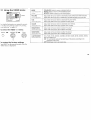
Remote Control
hi the instructions that follow, we will refer
tc_the buttons on llour remote control.
Keep this flap un_dded and look to this page
fcr reference.
SYSTEM OFF
(page 9 and 15)
DISPLAY
SLEEP
JUMP
_ TV/DBS
(page 20)
RESET
(page 19)
VOL +/-
CODE SET
(page 24)
MUTING
TV (POWER)
TV (FUNCTION)
PIP (page 16)
TV/VIDEO
ANT (page 3 and 15)
0-9 buttons
ENTER
MTS (page 20)/GUIDE
Select buttons
(page 12 and 18)
MENU
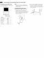
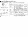
Getting to know the buttons on the
remote control
Names of the buttons on the remote control are
presenLe(i in different colors to represent the
available functions.
Button color
TransFarent .........
Press to select the componenL
you want to control; e.g.
VTR (VCR), DBS (Direct
Broadcast Satellite)/CABLEo
or T_
Green ............... Buttons relevant to power
operations, like turning the
TV, DBS (Direct Broadcast
Satellite)/CABLE, or VTR
(VCR) on or off.
Label co or
White ............... TV/VTR (VCR)/DBS (Direct
Broadcast Satellite) / CABLE
opera tion buttons.
Yellow ............... PIP operation buttons.
Blue ................. DBS (Direct Broadcast
Satellite) operation buttons.
Green ................ S-Link operation buttons.
For a detailed explanatio_t of most buttons, see
"Watchi:zg rite I3/" on page 14.

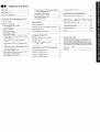
Table of Contents
41elcome! ........................................ 1
_recautions ...................................... I
Jsing This Manual ........................... I
-.onnectfng and Installing the TV
::onnector Types .......................................... 2
daking C onnections .................................... 2
Conno:ting directly to cable
or m_antenna ........................................ 2
Cable or antenna ...................................... 3
Cable and antenna ................................... 3
Conno__ng a cable box ............................ 3
Cable box and cable ................................. 3
Conne:ting an antenna/cable TV system
with a VCR .......................................... 4
Corme:ting to an S Video equipped
VCP ..................................................... 4
Conne:_g a VCR amd TV with a cable
bOX ....................................................... 5
Conne:'ting to an S Video equipped VCR
with a cable box ................................. 5
Connecting a DBS receiver ...................... 6
Connecting a DBS receiver and a VCR .... 6
Connecting an audio system ................... 7
Connecting an AV receiver ...................... 7
Connecting two VCRs for tape editing
using MONITOR OUT ....................... 8
Using the S-Link function ........................ 9
Connecting a camcorder .......................... 9
Installing the glass door ......................... 10
Adjusting the shelf ................................. 11
Basic Set Up
Inserting batteries ......................................... 12
Using the remote control Select buttons ..... 12
Adjusting sliders .......................................... 12
Chl Line Help/h_tructions .......................... 12
Using your New TV
Setting up the TV automatically .................. 13
Watching the TV .......................................... 14
Watd_ing two programs at one
time -- PIP ......................................... 16
Adjusting your SETUP (menus)
Learning menu selection ..............................18
Using the VIDEOmenu ...............................19
Using the AUDIO menu ..............................20
Using the TIMERmenu ...............................21
Using the SETUPmenu .............................22
Operating vicreo equipment
Setting the manu:!acturer's code ................... 24
Operating a cable box or DBS receiver
Progr_g the remote ..............................26
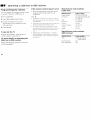
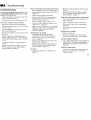
Troubleshooting ........................... 27
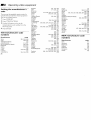
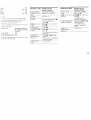
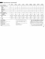
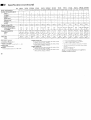
Specification,.: ................................ 28
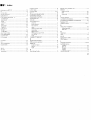
Index .............................................. 31
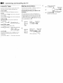
Owner's Record
The model and serial numbers are located at the rear
of the TV, below the Sony logo, on the sticker, and
also on the TV box (white label). Record these numbers
in the spaces provided below. Refer to them whenever
you call upon yoar !;ony dealer regarding this product.
Model No. KV-
Serial No.

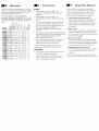
Welcome!
Thank you for purchasing the Sony Trinitron ®
Color TV. This manual is written for the models
listed bellow. Before reading, check the model
number on the rear of your TV.
Model KV-27S26 is used for illustration
purpose:s. The screens displayed are for model
KV-35V36. Differences in operation features are
indicated in the text; for example, "KV-27S26
only".
.2 _ /
Model _ _ _ ._
_E
Number _ _ ,
KV-27S26
KV-2?V26
!_l:_ZZ3__.ik:; o
KV-29RS26
KV29V36C i
KV-29V76_
KV 32536 •
KV-32V26
KV-34RS26C
1_,.3_Kt@(:Z: : c
KV35526 • •
KV35V36 • •
"KV'3_V_' _;'KV 37RS26 • •
Precautions
Safety
• Operate the TV only on 120 V AC
(except KV-29RS26C, 29V36C, 34RS26C,
34V36C).
Operate the TV only on 220 V AC
(KV-29RS26C, 29V36C, 34RS26C, 34V 36C
only).
The plug is designed, for safety purposes,
to fit in the wall outlet only one way. If
you are unable to insert the plug full_ into
the outlet, contact your dealer
(except KV-29RS26C, 29V36C, 34RS26C,
34V36C).
• If any liquid or solid object should fall inside
the cabinet, unplug the TV immediatebT and
have it checked by qualified personnel
before operating it further.
• If you will not be using the TV for several
days, disconnect power by pulling the
plug itself. Never pull on the cord.
For details concerning safety precautions, see the
supplied leaflet "IMPORTANT SAFEG UARD'_;'.
Installing
• To prevent internal heat build-up, do not
block the ventilation openings.
• Do not install the TV in a hot or hum: d
place, or in a place subject to excessi_.e
dust or mechanical vibration.
Using This Manual
This manual is divided into four major
sections. We recommend that you carefully
review th _ contents of each section in the
order pro_,ided to ensure that you fully
unders:and the operation of your new TV.
1 Connecting and Installing the IV.
This section will guide you through your
initial _;et up. It will slnow you how to
connect your new components, connect to
your antenna or cable, and connect any
accessories.
Basic Set Up.
This section will teach you the basic skills
needed to operate your new TV. It will
show you how to operate special functior_s
of the ::emote control.
3 Using your New TV
This s.:_ction will show you how to begin
using '!our new TV. It will show you how
to use the AUTO SET UP feature, and how
to use your remote control's features.
4 Adjusting your Set Up (menus).
This section will teaclh you how to access
or,,-screen menus and adjust your TV's
settings.
Instr;_ctio_::in this manualarc written for the remote
contrd. Si_i_:ilarcontrolsmay befound on the TV console.

II connecting and Installing the TV
Connector Types
_'OUmay J!ind it necessary to use some of the
:ollowing connector types during set up.
"oaxial (:able
;tandard TV Cable and Antenna connector
'lug Type
_t__, _@ Press onto connection
;crew-on Type
_ _ Screw onto connection
; Video Cable
tigh quaLty Video connector for enhanced
icture quality
__,, --_ _) Align guides and
press onto connection
_.udio/Video Cable
2onventional Audio/Video cable
::::=::_:_ _ @ Press onto connection
Yellow - Video
White -Audio (Left)
Red - Audio (Right)
;-Link Cable
;ony Link. connector (only available on Sony
_roducts) for simultanc.ous control of your
omponents
_2Z_=, --* @ Press onto connection
Making Connections
For best picture quality, a cable TV system or
outdoor antenna is recommended.
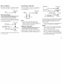
Connecting directly to cable or an
antenna
The connection you choose will depend c,n
the cable found in your home. Newer homes
will be equipped with standard coaxial cable
(see A); older homes will probably have 300-
ohm twin lead cable (see B); still other homes
may contain both (see C).
A
• VHF only 75-ohm (Rear of TV)
coaxial cable VHF/UHF
or
• VHF/UHF --_ ""_
or
• CaNe
• VHF only 300-ohm twin (Rear of TV)
lead cable VHF/UHF
• UHF only
or
• VHF/UHF / K£"_._
Antenna connector "N ..,_
C
• VHF
and
UHF: --
75-ohm coaxial cable
__i_._= i_ (Rear of TV)
_..J_ (not supplied)
300-ohm twin lead cable

:able or antenna
,lost simple connection. Connection is made
irectly from the cable or antenna to the TV.
Cable
(Rear of TV)
VHF/UHF
:able and antenna
KV-27S36, 27V36, 29V36C, 29V76M, 32S36, 32V36,
34V36C, 35S36, 35V36, 35V76, 37V36M only
ou may find it convenient to use the
)llowing :set up if your cable provider does
ot feature local channels that you are able to
:_ceive using an antenna.
(Rear of TV)
AUX
CATV cable
(No connection "TO (_
CONVERTER" in this case)
TO CONVERTER
Antenna cable
VHF/UHF
elect Cable or ANT mode by pressing ANT on
_eremote control.
Connecting a cable box
Some pay cable TV systems use scramblec or
encoded signals that require a cabIe box* to
view all channels.
(Rear of TV;
Cable VHF/UHF
! !
*Cable box
Note:
• If you will be controlling all channel
selection through your cable box you
should consider using the CHANNEL FIX
feature discussed on page 22.
Cable box and cable
• KV-27S36, 27V36, 29V36C, 29V76M, 32S36, 32V36,
34V36C, 35S36, 35V36, 35V76, 37V36M only
Some pay cable "IV systems use scrambled or
encoded signals requiring a cable box* only for
certain channels (e.g. HBO, SHOWTIME, _,tc.).
*Cable box (Rear of TV)
AUX
s.0mbl ;ZI
ch'mqels | TO CONVERTER
75-ohm coaxial i
cable (not supplied) ! (signal)
CATV cable
(urlsc "ambled channnels) VHFIUHF
For this set up, you can switch between scrambled
charmels (through your cable box), and normal
(CATV) channels by presskng ANT on your
remote cor.trol.
* Your Sony remote control can be programmed
to open: te your cable box (see page 26).
Notes:
• You ca anot watch the signal through the
"AUX" input as a window picture when
using P:cmre-in-Pic_re (PIP).
• If you a::e connec_ng a cable box through
the"AUX" input and would like to switdl
betw,_n the "AUX" m_d normal (CAW) input
you should consider using fl_eCHANNEL FIX
feature discussed on page 22.

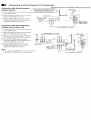
Connecting and Installing the TV (continued)
Disconnect all power sources before making any connection:;.
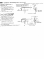
:onnecl:ing an antenna/cable TV
;ystem 'with a VCR
I ' _Attach the coaxial connector from your
cable or antenna to IN on your VCR.
), Using AUDIO/VIDEO connectors, connect
AUD_[O and VIDEO OUT on your VCR to
AUDIO and VIDEO IN on your TV
(Yellow-VIDEO, White-AUDIO Left, Red-
AUDIO Right).*
3 Using a coaxial connector, connect OUT on
your VCR to VHF/UHF on your TV.
I
VCR must be connected and turned on to operate PIP ]
(KV-27526, 27V26, 29R526, 29RS26C, 29V66M,32.;26,
}
32TW26, 321/26, 34R526C, 35526, 37R526 on/yL
Coaxial cable
vc. t
_olc _ Auo_. ,,l_Eo aV/;_?E_
Connecting to an S Video equipped
VCR (for optimum picture quality)
1 Attack. the coaxial connector from your
cable or antenna to IN on your VCR.
2 Using AUDIO conr, ectors, connect AUDIO
OUT on your VCR to AUDIO IN on your TV
(Wt'dte-AUDIO Left, Red-AUDIO Right).*
3 Using a coaxial connector, connect OUT on
yourVCR to VHF/UHF on your TV.
4 Using an S VIDEO connector, connect
S VIDEO on your VCR to S VIDEO on
your TV.
If you are connecting a monaural VCR,connect only
fl_esingle audio output to the left input on },'ourTV.
Note on DVD Connection:
• For the best picture quality, connect the DVD player directly to the TV.
Refer to your DVD manual for detailed connection information.
4
,,Rear of TV)
I's@'l I ....
_-- 0 , 0 --'
__ UDIO-R (red)
AUDIO-L (white)
VIDEO (yellow)
r
VMC-810S/820S (nat supplied)
3
Cable I_ o_'_
Coaxial cable
VCR
? l,
2
(Rear of TV)
','JDE0 JJ
svoEo _
S VIDEO
AUDIO-R (red)
YC-15V/30V AUDIO-L (white)
(not supplied)
I
RK-74A (not supplied)

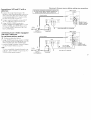
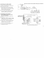
Connecting a VCR and TV with a
cable box
Connect the single (input) jack of the
Splitter to your incoming cable connection,
and connect the other two (output) jacks
(using coaxial cable) to IN on your cable
box and VHF/UHF on your TV.
Using a coaxial connector, connect OUT
on yo_;.r cable box to IN on your VCR.
Using AUDIO/VIDEO connectors,
connect AUDIO and VIDEO OUT on your
VCR to AUDIO and VIDEO IN on your
TV (Yellow-ViDEO, White-AUDIO Left,
Red-AUDIO Right).
.'onnecting to an S Video equipped
/CR with a cable box
for optimum picture quality)
I-2 Perform as described above.
I Using AUDIO connectors, connect AUDIO
OUT on your VCR to AUDIO IN on your TV
(White-.AUDIO Left, Red-AUDIO Right).
Using an S VIDEO connector, connect S VIDEO
on your VCR to S VIDEO on your TV.
lote:
To view scrambled channels through },our
cable box, select VIDEO 1 by pressing TVi
VIDEO on the remote control.
Disconnect all power sources before making any connections.
VCR must be connected and turned on to operate PIP I
(KV-27S26, 27V26, 29RS26, 29RS26C, 29V66M,32S26, I
32TW26, 321/26, 34RS26C, 35S26 37R526 on]/). I
Coaxial cable
VCR
H
Cable _:_- ____
Splitter Cable box
(not supplied)
(Rear of TV)
r VlBEO itT--i
.'Hr 'JHr AUO:; OUT
....._:,-,,_ _:_
_up,o _,'K :,_1,_: I
',/_---- VIDEO (yellow)
VMC-810S/820S (not supplied)
(Rear of TV)
1
Cable
Coaxial cable
VCR
....
Splitter
(not supplied)
YC-15Vi30V
(not su 3plied)
__ S VIDEO
AUDIO-R (red)
AUDIO-L (white)
RK-74A (not ,supplied)
Cable box

Connecting a DBS (Direct Broadcast
Satellite) receiver
1 Conrect the cable from }'our satellite antenna
to your DBS receiver.
2 Attach the coaxial connector from your cable or
antenna to VHFiUHF on your TV.
3 Using AUDIO/VIDEO connectors, connect
AUDIO and VIDEO OUT on your DBS receiver
to AUDIO and VIDEO IN on your TV.
Connecting and Installing the TV (continued)
Disconnect all power sources before making any connections.
Connecting a DBS (Direct Broadcast
Satellite) receiver and a VCR
1 Connect the cable from your satellite antenna
to your DBS receiver.
2 Attach the coaxial connector from your cable or
antenna to VHFiUHF-IN on your VCR.
3 Using a coaxial connector, connect VHF!UHF-
OUT on your VCR to VHF/UHF on your TV.
4 Using AUDIO/VIDEO connectors, connect
AUD]O and VIDEO OUT on your DBS receiver to
AUDIO and VIDEO IN on your VCR.
5 Using AUDIO/VIDEO connectors, connect
AUDIO and VIDE() OUT on your VCR to
AUDIO and VIDE() IN on your TV.
I
Note:
• To view input from the DBS or VCR, select VIDEO 1
by pressing TV/VIDEO on the remote control.
6
For the highest picture quality, use S VIDEO I
instead of the yellow AUDlONIDEO cable. See I 2
your DB5 manual for more information,
DBS receiver _-
S_TELL"_ IN
antenna/ _,_--_-'_ J
cable
(Rear of TV)
SVl_ o _
VH_,LHF ! iAUO,OOW
R ! n
#r-C_r-_r--- AU DIO-R (red)
_ _ AUDIO-L (white)
'-- VIDEO (yellow)
3 T
VMC-810S/820S (not supplied)
DBS receiver
VIDEO(yellow)-_
AUDIO-L (white)
AUDIO-R (red)
VMC-810S/820S (not supplied)
VCR _ 2 I
(Rear of TV)
_HF,UHF AUDIOOUT
VIDEO ' : :'
R _
T
VM 2-810S/820S (not: supplied)

Connecting an audio system
For greater viewing pleasure, integrate your
home stereo into the system.
1 Using AUDIO connectors, connect AUDIO
OUTon your TVto one ofthe unused Line
inputs (e.g.Tape-2,etc.)on your stereo (White-
AUDIO Left,Red-AUDIO Right).
2 Set yo_arstereo to the chosen Line input
and refer to page 20 of this manual for
additional audio setup instructions.
Connecting an AV receiver
• KV-27V:I6, 29V36C, 29V76M, 32V36, 34V36C,
35V36, 35V76, 37V36M only
For greater viewing pleasure, connect your
AV receiver.
1 Using AUDIO/VIDEO connectors, connect
VIDE() 1 IN on your TV to Monitor AUDIO
and V] DEO OUT on your AV receiver.
2 Using AUDIO/VIDEO connectors, connect
TV OUT on your TV to TV AUDIO and
VIDE() IN on your AV receiver.
You may want to use CHANNEL FIX to fix your
FV's inpu;! to theAV recefver (VIDEO 1).
5ee CHANNEL FIX, page 22.
Disconnect all power sources before making any connections.
(Rear of TV)
v7
L i q_ I ' L
AuoIO ;<, /,_ R
1
AUDIO-L (white)
_ <=_=,...>
AUDIO-R(red)
RK-74A
(not supplied)
1
_'_t input Vt ! I_ I
AUO,O-R<ro0, VMC-810S,8201,:oct.u0p,,.>1
AUDIO-L (white) _ _ 1 /
V' DEO (yell ow) _,rr_lyl _ (R_,ar of KV-27V36_) ] /_V outputs
AUDIO-/(whi,e)--:_} 0 2 Y Av inputs
7

Connecting and Installing the
:onnecl:ing two VCRs for tape
._diting using MONITOR OUT
KV-27V26, 27V36, 29V36C, 29V66M, 29V76M,
32V26, 32V36, 34V36C, 35V36, 35V76, 37V36M only
,4ONITOR OUT gives you the ability to use a
econd VCR to record a program being played
}y the primary VCR or to perform tape
,diting and dubbing.
[ Connect the VCR intended for playback
using t]_e setup instructions on page 4 of
this manual.
Using AUDIO/VIDEO connectors,
connec: AUDIO and VIDEO IN on your
VCR intended for recording to MONITOR
AUDIO and VIDEO OUT on your TV.
TV (continued)
Disconnect all power sources before making any connection._.
VCR (for playback)
tINE IN
out
I
VMC-8105/8205 (not supplied)
(Rear of TV)
iN
..... ....
VCR (for recording)
..................oo, :1
2 _ ___ VIDEO (yellow)AUDIO-I (white)
AUDIO-R (red)
I
VMC-8" 0S/820S (not supplied)
_lotes:
, Do not change the input signal while
editing through MONITOR OUT.
When connecting a single VCR to the TV;
if VCR LINE OUT is connected to TV
VIDEO IN, do not connect the TV
MONITOR OUT jacks to the VCR LINE
INPUT (see right). Doing so will cause
program interference and other viewing
problems.
[X(RearofTV)/
Indicates direction
of tdgnal

Using the S-Link function
, KV-27V26, 27V36, 29V36C, 29V66M, 29V76M, 32V26,
32V36, 34V36C, 35V36, 35V76, 37V36M only
;-Link is a Sony innovation designed to make
your Son}' components work together. It allows
you to aul:omatically switch theTV input mode
:o video v:hen you press PLAY on your Sony S-
Link VCR. It also allows you to turn the VCR
md TV otf at the same Lime with the SYSTEM
DFF button.
1 Connect your VCR using the setup
instructions on page 4 of this manual.
Z Using an S-Link connector, connect the
S-LINI< jacks on your VCR and TV. Ensure
that both ends are seated firmly and that the
TV S-LINK connector is in the same row as
the AI2 DIO/VIDEO connectors.
Disconnect all power sources before making any connections.
VCR
AUDIO-L (white) _-- S-LINK
VIDEO (yellow) "_I_ _ (black)
I
AudiolVideo Cable
(not supplied)
(Rear of TV)
_N SVI{IEO i___O_UT
2
(Front of KV-32V36, 34V36C,
35V36, 35V76, 37V36M)
Connecting a camcorder
, KV-27V26, 27V36, 29V36C, 29V66M, 29V76M, 32V26,
32V36, 34V36C, 35V36, 35V76, 37V36M only
['his connection is convenient for viewing a
)icture directly from your camcorder.
_Jsing AUDIO/VIDEO connectors, connect
\UDIO and VIDEO OUT on your camcorder to
\UDIO and VIDEO IN _n the frontpanel of your
['V (Yellow-VIDEO, White-AUDIO Left, Red-
XUDIO Right).
_ote:
If you are connecting a monoaural camcorder, connect only
the single audio output to the left input on your TV.
VIDE,) 2 INPUT
Ifyou have an S Video equipped camcorder, _ _ .
you can use an SVideo connection for
optimum picture quality,
VtDI!O(yelI°w)_ @,,,xCAUDlO-R(red)
K y .;-'-'-'-'-'-'-'-'_AUDIO-L(white)
AV output "
VMC.810S/820S'] ''/
___ ,_,_-,,,,_ (not supplied) l
E',-_,,,',o,,"_-:_%-_,'.S4_"_=/"

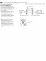
_H Connecting and Installing the TV (continued)
(V-32TW26 and KV-35V76 only
:ollow these instructions to install the glass
toor and adjust the shelf.
Note:
• Confirm ttuat all parts are included before
beginnh_g assembly. If any parts are missing,
contact your dealer.
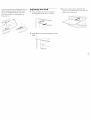
Installing the glass door
1 Check that the projection of the screw
through the bottom hinge A does not
interfere with the proper installation o; the
hinge to the glass door, and then insert the
hinge into the hole located at the bottom
right side of cabinet.
Push here to close.
To open, push again.
Parts List
A Bottam hinge _ 1
B Top hinge _ 1
C Screw 4x4 _ 4
D
pad _ 1
Plate
E Plate _ 1
F Metal pin _ 4
C
2 Attach :he top hinge B to the right side of
the g[ass door; tighten the screws snugly,
but do not overtighten. Attach the plate
pad D to the left side and push the plate I:
over the plate pad.
B

Pushthetopglassdoorhingeintothetop
rightbushingandgentlyslidetheglass
doorintothebottomhinge.Adjustthe
glassdooruntillevel,andtightenthe
hingescrews.
Adjusting the shelf
1 Press the upper part of the temporary
shelf supports and remove the shelf.
2 Insert the metal pin shelf supports (2 each
side).
3 InserI tt-e shelf, ensuring that the pin
supporl:_ are seated in the grooves on the
botto:n _ide of the shell!.
Metal pin
1"1

_ Basic Set up
Inserting batteries
Insert two size AA (R6) batteries (supplied) by
matching the + and - on the batteries to the
diagram inside the battery compartment.
Notes:
• Remove the batteries to avoid damage
from possible battery leakage whenever
you ar ticipate that the remote control will
not be used for an extended period.
• Handle the remote control with care.
Avoid dropping it, getting it wet, or
placing it in direct sunlight, near a heater,
or where the humidity is high.
• Your remote control can be programmed to
operate most video equipment. See page 24.
Using the remote control
Select buttons
_o_ CH
Select
The supplied remote control has select
buttons which allow for movement of the on-
screen selector in four directions. Pressing; on
the edge of the select buttons will cause the
selector to movL"in the selected direction.
Pressing the center of the select buttons ".2E "
will activate the selected item.
Adjusting sliders
When menu items present a slider (,,,,_I:,_L_,,.........or
............_,,.,,,,,,,,.),use the select buttons (It or I_) to adjust
the setting.
On Line Help/Instructions
Several n"enu windows will provide prompts
and instructions to assist: you in navigating
throt, tgh the different functions. When
presented, use these to sup]dement the instructior_s
in this ma:lual.

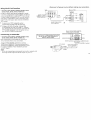
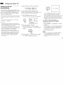
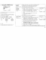
Using your New TV
;ettincl up the TV
tutomatically
he EASY SETUP GUIDE feature wqll allow you
set the on-screen language and set all receivable
hannels. The EASY SETUP GUIDE screen will
ppear evelT time you turn on the TV until you
erform AUTO PROGRAM.
'he EASY SETUP GUIDE feature does not apply
_rinstallations that use a cable box for all chmmel
qcction.
b set up the TV manually, refer to "Using the
ET UP mer!!" on page 2.2.
ips "'_"
Pe_onn thisfimction during the day, with the antenna
and/or cableproperly connected, to ensure that all available
channels will bebroadcasting and receivable.
After using EASY SETUP IF,UIDE you will still have the
option of adjusting any of the,,system settings, likeerasing
channels, through the SET UP menu (page22).
The TV must besetto TV inpv:.tto executeAUTO
PROGRAM. PressAiXrI"unti.!thechanne!number appo_rs.
If your cable or antenna is connected to AUX, then
press ANT until "AUX" appears next to the channel
mmlber. (KV-27S36, 271736, 29V36C, 29V76M,
32S36, 31'.V36, 34V36C, 35S36, 35V36, 35V76,
37V36M only)
Using the buttons on the front of the TV:
SETt_p TV,'_IDEO - VOLUUE÷ C_AN_EL÷ po_E_
olJ tZD U
For KV-27V36, 29V36C, 29V76M, 32V36,
34V36C, 35V36, 35V76 and 37V36M, the cot troI
buttons are located on tt_e top of the TV.
1 Press POWER to turn on the TV.
The EASY SETUP GUIDE screen appears.
POWER
ENGLISH : [CH÷]
ESPANOL : [CH-]
AUTO SET UP : [VOL-]
DEMO : [TV/VIDEO
First please connect
the antenna
Press ]SET UP] to exit.
2 (Except Canadian models)
Press CHANNEL + to select English
screens or CHANNEL - to select Spanish
screens.
- CHANNEL +
3 Press VOLUME - to continue or TV!\qDEO
for a DEMO of hmcfions and menus.
-" VOLUME+
AUTO PROGRAM
"ALTFO PROGRAM" appears and the TV
starts scammlg m_d presetting chalmels
automatically. When all the receivable charmels
are stor_d, the lowest numbered charmel is
displayc:d. If the TV receives cable TV chalmek%
CABLE is set ON automatically.
To perfolrm AU¥O SET UP again
• Press SET UP.
PrL_s CHANNEL + or Ct4ANNEL- to select a
language.
Press Volume - to restore factory settings
("CONTINUE TO AUTO PROGRAM?"
will appear on the screen. Press CH+ to
execute or CH- to exit).
• Press SET UP to exit.
Note:
• When ,,ou perform AUTO PROGRAM,
your CHANNEL FIX, TIMER, and
CHANNEL BLOCK settings will be
erased.
1"|

Jill using your New TV (continued)
Watching the TV
All of the TV features can be accessed via the
re'mote control. The following chart will
explain the function of the buttons found on
,our remote control
REFER TO THE
ILLUSTRATION OF THE
REMOTE CONTROL ON THE
INSIDE FRONT COVER OF
THIS MANUAL AS YOU
REVIEW THIS CHART
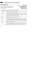
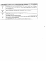
TV (FUNCTION) Activates the remote control for use with the TV.
TV POWER Turns the TV on and off. If "VIDEO" appears on the screen, press TV/VIDEO
or ANT so that a channel number appears.
('_. (_"l Use for direct channel selection. Press 0-9 to select a channel (for example,
to select channel 10, press 1 and 0), the channel will change after 2 seconds,
or you can press ENTER for immediate selection.
CH +/- Press to scan through the channels (+ up or - down).
VOL +/- Press to adjust the volume (+ up or - down).
JUMP Press to alternate or jump back and forth between two channels. You can only
jump between the last two channels that have been selected with the 0-9 keys.
MUTING Press to mute the sound ("MUTING" will appear on the screen). Press again
or press VOL + to restore sound.
FREEZE- Press to freeze the window picture while in PIP mode. If you are not in PIP
mode, pressing FREEZE will cause the main picture to freeze into a window
picture. Great for copying down phone numbers, addresses, recipes, etc.

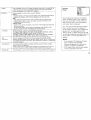
SLEEP PressrepeatedlyuntiltheTVdisplaystheapproximatetimeinminutes(30,60,
or90)thatyouwanttheTVtoremainonbeforeshuttingoffautomatically.
Cancelbypressinguntil"SLEEPOFF"appears.
•DISPLAY
TV/VIDEO
Pressrepeatedlytostepthroughavailabledisplays:
Status
Channelnumber,currenttime,channelcaption(ifset),andMTSmode(ifSAPis
selected)aredisplayed.SAPindicationdisappearsafterthreeseconds.
XDS
XDS(ExtendedDataService)showsanetworkname,programname,
programtype,programlength,callletters,andtimeoftheshowifthe
broadcasterolfersthisservice.
CaptionVision
CaptionVisionwillbedisplayedonthescreenifthebroadcasteroffersthis
service.(seeright)
Tocancelthedisplay,pressDISPLAYrepeatedlyuntil"DISPLAYOFF"
appears."DISPLAYOFF"disappearsafterthreeseconds.
Pressrepeatedlytostepthroughavailablevideoinputs:
TV,Video1andVideo2(KV-27S26,27S36,29RS26,29RS260,32S26,
32S36,32TW26,34RS26C,35S26,35S36,37RS26only)
TV,Video1,Video2andVideo3(KV-27V26,27V36,29V36C,29V66M,
29V76M,32V26,32V36,34V36C,35V36,35V76,37V36Monly)
ANT PresstochangetheVHF!UHFinputtotheAUXinput(KV-27S36,27V36,
(AUX input) 29V360, 29V761vl,32S36, 32V36, 34V36C, 35S36, 35V36, 35V76, 37V36M only)
For detailed connection information, see "Cable box and cable" or "Cable and
antenna" on page 3.
SYSTEM OFF KV-27V26, 27V36, 29V36C, 29V66M, 29V76M, 32V26, 32V36, 34V36C,
35V36, 35V76, 37V36M only.
Press to turn off the TV and all other equipment connected with S-Link and
return the TV input to either antenna or AUX, whichever was last used.
MTStG UIDE Pressthis button to cycle through the Multi-channel TV Sound (MTS) options.(page 20)
CAPTION
VISION
CAPTION VISION
_.lz] 1
_Tt
i_ 1 TEXT 2
I_t TEXT 3
TEXT 4
_MENU
Some programs are broadcast with Caption
Vision. Io display Caption Vision, select CC1,
CC2, CC3, CC4, TEXT1, TEXT2, TEXT3, or
TEXT4 from the menu, then press DISPLAY
until Caption Vision is displayed.
CC1, CC2, CC3, or CC4 shows you a caption,
that is, a printed version of the dialogue or
sound effects of a program. (]he mode should
be set to CO1 for most programs) TEXT1,
TEXr2, TEXT3, or TEXT4 shows you text, that
is, inf3rmation presented using either half or the
whole; screen. It is not usually related to the
program•
Notes:
• Poor reception of TV programs can cause
err3rs in Caption Vision and XDS.
Captions may appear with a white box or
other errors instead of intended text•
• XCS, Caption Vision, and the status display
cannot be used at the same time.
15

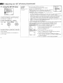
Using your New TV (continued)
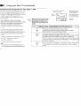
Natching two programs at one time m PIP
7he Picture-in-Picture (PIP) feature allows you
o view two channels simultaneously, one in
he full size "main" picture and one in a smaller
'window" picture. This means that two
eparate tuners must be available to provide
he two signals.
2ertain mcxtels (KV-27S26, 27V26, 29RS26,
:9RS26C, 2c'V66M, 32S26, 32TW26, 34KS26C, 35S26,
.7RS26oN3,')are equipped with a single tuner.
"his simply means that a VCR must be
onnected and turned on for PIP to operate.
'o e_sure acorrectsingle tuner PIP connection (KV-
7S26,27V26, 29RS26, 29RS26C, 29V66]vl,32S26,
2TW26,34RS26C, 35S26, 37RS26 only), makesure the
,flowinglist of simple connections is complete before
sing PIP:
tk cable or antenna is connected to the VCR
The VCR is connected to your TV
The VCR is turned on
or detailedconnection information, seepage3-5)
lote:
You must press TV (FUNCTION) before you
can conb:ol PIP with the yeUow labeled buttons.
_ REFERTO THE ILLUSTRATION OF
THE REMOTE CONTROL ON THE
INSIDE FRONT COVER OF THIS
MANUAL AS YOU REVIEW THIS
CHART
The sound of the main
picture is received,
Main
picture--
Input-source mode
/ or TV channel for
"\ / the main picture
___ _ " d' 6r...Input-sourcemode
X_'_%. ,,_-_ , I///" or TV channel for
_V I LJ_J / , .
"_\ "_<_" _ | the window picture
I
;q.-.._l . _LI_ Window
-T p,cture
PIP
TV/VIDEO
®
AUDIO
®
Press once to display the window picture (119 size).
Press again to reduce the size of the window picture, (1/16 size).
Press a third time to remove the window picture.
Press repeatedly to step through available video inputs:
TV, Video 1, Video 2, and Video 3 (KV-27V26, 27V36, 29V360, 29V66M,
29V76M, 32V26, 32V36, 34V36C, 35V36, 35V76, 37V36M only)
If you use one of the connections horn page 4, your PIP input source is the
VCR. Ifyou use one of the connections from page 5, your PIP input source
is a VCR or cable box.
Press to alternate sound between tqe main picture and the window picture.
A _ will appear for a few seconcls to indicate which 3icture is receiving
sound.
Page is loading ...
Page is loading ...
Page is loading ...
Page is loading ...
Page is loading ...
Page is loading ...
Page is loading ...
Page is loading ...
Page is loading ...
Page is loading ...
Page is loading ...
Page is loading ...
Page is loading ...
Page is loading ...
Page is loading ...
Page is loading ...
Page is loading ...
Page is loading ...
-
 1
1
-
 2
2
-
 3
3
-
 4
4
-
 5
5
-
 6
6
-
 7
7
-
 8
8
-
 9
9
-
 10
10
-
 11
11
-
 12
12
-
 13
13
-
 14
14
-
 15
15
-
 16
16
-
 17
17
-
 18
18
-
 19
19
-
 20
20
-
 21
21
-
 22
22
-
 23
23
-
 24
24
-
 25
25
-
 26
26
-
 27
27
-
 28
28
-
 29
29
-
 30
30
-
 31
31
-
 32
32
-
 33
33
-
 34
34
-
 35
35
-
 36
36
-
 37
37
-
 38
38


Ask a question and I''ll find the answer in the document
Finding information in a document is now easier with AI
Related papers
Other documents
-
Aiwa HV-FX9000U User manual
-
Zenith Sentry 2 SLS1935W Operating Manual & Warranty
-
Pioneer SD-P4053 Owner's manual
-
Philips MAGNAVOX MAT960 User manual
-
RCA D940 User manual
-
-
RetroSound Exile LED Monitor Owner's manual
-
moon 820S User manual
-
-