Page is loading ...

November 2009
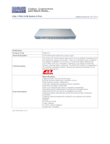
ACU1001A
ACU1002A
ACU1004A
ACU1005A
ACU1008A
ACU1009A
ACUREM
ACUSREM
CAT KVM Extender
5


THE SERVSWITCH™ FAMILY
1
Welcome to the ServSwitch™ Family!
Thank you for purchasing a BLACK BOX® ServSwitch™ Brand CAT5 KVM Extender
model! We appreciate your business, and we think you’ll appreciate the many ways that your
enhanced keyboard/video/mouse system will save you money, time, and effort.
That’s because our ServSwitch family is all about breaking away from the traditional,
expensive model of computer management. You know, the one-size-fits-all-even-if-it-doesn’t
model that says, “One computer gets one user station, no more, no less.” Why not a single
user station (monitor, keyboard, and mouse) for multiple computers—even computers of
different platforms? Why not a pair of user stations, each of which can control multiple
computers? Why not multiple user stations for the same computer?
With our ServSwitch products, there’s no reason why not. We carry a broad line of robust
solutions for all these applications. Do you have just two PCs, and need an economical
alternative to keeping two monitors, keyboards, and mice on your desk? Or do you need to
share dozens of computers, including a mix of IBM® PC, RS/6000®, Apple® Macintosh®,
Sun Microsystems®, and SGI™ compatibles among multiple users with different access
levels? Does your switch have to sit solidly on a worktable and use regular everyday cables?
Or does it have to be mounted in an equipment rack and use convenient many-to-one cables?
No matter how large or small your setup is, no matter how simple or how complex, we’re
confident we have a ServSwitch system that’s just right for you.
The ServSwitch™ family from Black Box—the one-stop answer for all your KVM-switching
needs!
This manual will tell you all about your new ServSwitch™ Brand CAT5 KVM Extender,
including how to install, operate, and troubleshoot it. For an introduction to the Extender, see
Chapter 2. The Extender product codes covered in this manual are:
ACU1001A ACU1002A
ACU1004A ACU1005A
ACU1008A ACU1009A
ACUREM ACUSREM
User Guide Revision: 2.0 (November 2009)

THE SERVSWITCH™ FAMILY
2
Copyrights and Trademarks
©2002/9. All rights reserved. This information may not be reproduced in any manner without
the prior written consent of the manufacturer.
Information in this document is subject to change without notice and the manufacturer shall
not be liable for any direct, indirect, special, incidental or consequential damages in
connection with the use of this material.
All trademark and trade names mentioned in this document are acknowledged to be the
property of their respective owners.
Disclaimer
While every precaution has been taken in the preparation of this manual, the manufacturer
assumes no responsibility for errors or omissions. Neither does the manufacturer assume any
liability for damages resulting from the use of the information contained herein. The
manufacturer reserves the right to change the specifications, functions, or circuitry of the
product without notice.
The manufacturer cannot accept liability for damage due to misuse of the product or due to
any other circumstances outside the manufacturer’s control (whether environmental or
installation related). The manufacturer shall not be responsible for any loss, damage, or injury
arising directly, indirectly, or consequently from the use of this product.
Cautions and Notes
The following symbols are used in this guide:
CAUTION. This indicates an important operating instruction
that should be followed to avoid any potential damage to
hardware or property, loss of data, or personal injury.
NOTE. This indicates important information to help you make the best use of
this product.

FCC/CDC STATEMENTS
3
FEDERAL COMMUNICATIONS COMMISSION
AND CANADIAN DEPARTMENT OF COMMUNICATIONS
RADIO-FREQUENCY INTERFERENCE STATEMENTS
This equipment generates, uses, and can radiate radio-frequency energy, and if not installed
and used properly, that is, in strict accordance with the manufacturer’s instructions, may
cause interference to radio communication. It has been tested and found to comply with the
limits for a Class A computing device in accordance with the specifications in Subpart B of
Part 15 of FCC rules, which are designed to provide reasonable protection against such
interference when the equipment is operated in a commercial environment. Operation of this
equipment in a residential area is likely to cause interference, in which case the user at his
own expense will be required to take whatever measures may be necessary to correct the
interference.
Changes or modifications not expressly approved by the party responsible for compliance
could void the user’s authority to operate the equipment.
Shielded cables must be used with this equipment to maintain compliance with radio
frequency energy emission regulations and ensure a suitably high level of immunity to
electromagnetic disturbances.
This digital apparatus does not exceed the Class A limits for radio noise emission from digital
apparatus set out in the Radio Interference Regulation of the Canadian Department of
Communications.
Le présent appareil numérique n’émet pas de bruits radioélectriques dépassant les limites
applicables aux appareils numériques de la classe A prescrites dans le Règlement sur le
brouillage radioélectrique publié par le Ministère des Communications du Canada.

DECLARATION OF CONFORMITY
4
EUROPEAN UNION COMPLIANCE STATEMENT
WARNING!
This is a class A product. In a domestic environment, this product may cause
radio interference, in which case the user might be required to take adequate
remedial measures.
This product complies with the following harmonized standards for Information Technology
Equipment: EN55022:2006 (Class A), EN55024:1998 + A1:2001 + A2:2003.
To maintain compliance the use of correctly installed shielded (STP/FTP) interconnection
cable is advised. Only use CPU cables and power supplies provided (or recommended) for
use with this product.
When used in environments that have high levels of electromagnetic interference or excessive
power ground noise, you may experience disturbances to video and/or data transmission. If
this is the case, please refer to the Troubleshooting section of the User Guide for further
information, or contact Technical Support. In electrically noisy environments, the use of
shielded (STP/FTP) rather than unshielded (UTP) interconnection cable is recommended.

NOM STATEMENT
5
NORMAS OFICIALES MEXICANAS (NOM)
ELECTRICAL SAFETY STATEMENT
INSTRUCCIONES DE SEGURIDAD
1. Todas las instrucciones de seguridad y operación deberán ser leídas antes de que el
aparato eléctrico sea operado.
2. Las instrucciones de seguridad y operación deberán ser guardadas para referencia futura.
3. Todas las advertencias en el aparato eléctrico y en sus instrucciones de operación deben
ser respetadas.
4. Todas las instrucciones de operación y uso deben ser seguidas.
5. El aparato eléctrico no deberá ser usado cerca del agua—por ejemplo, cerca de la tina de
baño, lavabo, sótano mojado o cerca de una alberca, etc..
6. El aparato eléctrico debe ser usado únicamente con carritos o pedestals que sean
recomendados por el fabricante.
7. El aparato eléctrico debe ser montado a la pared o al techo sólo como sea recomendado
por el fabricante.
8. Servicio—El usuario no debe intentar dar servicio al equipo eléctrico más allá a lo
descrito en las instrucciones de operación. Todo otro servicio deberá ser referido a
personal de servicio calificado.
9. El aparato eléctrico debe ser situado de tal manera que su posición no interfiera su uso.
La colocación del aparato eléctrico sobre una cama, sofá, alfombra o superficie similar
puede bloquea la ventilación, no se debe colocar en libreros o gabinetes que impidan el
flujo de aire por los orificios de ventilación.
10. El equipo eléctrico deber ser situado fuera del alcance de fuentes de calor como
radiadores, registros de calor, estufas u otros aparatos (incluyendo amplificadores) que
producen calor.
11. El aparato eléctrico deberá ser connectado a una fuente de poder sólo del tipo descrito en
el instructivo de operación, o como se indique en el aparato.
12. Precaución debe ser tomada de tal manera que la tierra fisica y la polarización del equipo
no sea eliminada.
13. Los cables de la fuente de poder deben ser guiados de tal manera que no sean pisados ni
pellizcados por objetos colocados sobre o contra ellos, poniendo particular atención a los
contactos y receptáculos donde salen del aparato.

NOM STATEMENT
6
14. El equipo eléctrico debe ser limpiado únicamente de acuerdo a las recomendaciones del
fabricante.
15. En caso de existir, una antena externa deberá ser localizada lejos de las lineas de energia.
16. El cable de corriente deberá ser desconectado del cuando el equipo no sea usado por un
largo periodo de tiempo.
17. Cuidado debe ser tomado de tal manera que objectos liquidos no sean derramados sobre
la cubierta u orificios de ventilación.
18. Servicio por personal calificado deberá ser provisto cuando:
A: El cable de poder o el contacto ha sido dañado; u
B: Objectos han caído o líquido ha sido derramado dentro del aparato; o
C: El aparato ha sido expuesto a la lluvia; o
D: El aparato parece no operar normalmente o muestra un cambio en su desempeño; o
E: El aparato ha sido tirado o su cubierta ha sido dañada.

SAFETY PRECAUTIONS AND INSTALLATION GUIDELINES
7
Safety Precautions and Installation Guidelines
To ensure reliable and safe long-term operation please note the following installation
guidelines:
• Do not use to link between buildings.
• Only use in dry, indoor environments.
• If the building has 3-phase AC power, try to ensure that equipment connected to the
Local and Remote Units is on the same phase.
• Try not to route the CATx link cable alongside power cables.
• The use of shielded CATx cable is recommended to maintain compliance.
• Ensure that the system connected to the Local Unit is connected to power ground.
• Ensure that the monitor connected to the Remote Unit is connected to power ground and
does not use an isolated power supply.
• The Remote Unit and any power supplies can get warm. Do not situate them in an
enclosed space without any airflow.
• Do not place the power supply directly on top of the Remote Unit.
• This product is not suitable for use in isolated medical environments.
To safeguard against personal injury and avoid possible
damage to equipment or property, please observe the
following:
• Only use power supplies originally supplied with the
product or manufacturer-approved replacements. Do not
attempt to dismantle or repair any power supply. Do not
use a power supply if it appears to be defective or has a
damaged case.
• Connect all power supplies to grounded outlets. In each
case, ensure that the ground connection is maintained
from the outlet socket through to the power supply’s AC
power input.
• Do not attempt to modify or repair this product, or make
a connection from the CAT5 link interface (RJ45) to any
other products, especially telecommunications or
network equipment.

CONTENTS
8
Contents
1. Quick Setup 10
2. Overview 11
2.1 Introduction 11
2.2 Glossary 11
2.3 Features 13
2.4 Product Range 14
2.5 Compatibility 15
2.6 How to Use This Guide 16
3. Installation 17
3.1 Package Contents 17
3.2 Interconnection Cable Requirements 18
3.3 Remote Unit Installation 19
3.4 Connecting the Remote Unit 21
3.5 Local Unit Installation 24
3.6 Connection to Local Hubs 27
4. Remote Unit Configuration & Operation 29
4.1 Video Configuration Overview 29
4.2 Video Adjustments 30
4.3 Other Remote Configuration & Operation Options 32
5. Local Unit Operation 34
5.1 Overview 34
5.2 Operation of Dual Access Local Units 35
6. Troubleshooting & FAQ 37
6.1 Video 37
6.2 Serial 38
6.3 Keyboard & Mouse 39
6.4 General Questions 40

CONTENTS
9
Appendix A: Example Application 41
Appendix B: Rack Mount Options 45
Appendix C: Advanced Cabling Issues (Skew) 46
Appendix D: Serial Port Setup and Operation 48
Appendix E: Calling Black Box 51
Appendix F: Specifications 52

QUICK SETUP
10
1. Quick Setup
This section briefly describes how to install your KVM extender system and optimize the
video signals. Unless you are an experienced user, we recommend that you follow the full
procedures described in the rest of this manual.
.
Any Problems?
See Installation and
Troubleshooting sections.
Adjust Brightness and Focus controls
Optimize video quality on remote console monitor (See page
30)
Provides useful image for
adjusting video.
No
Serial Extender?
Yes
Set Baud Rate and Flow Control Jumpers
Set jumpers on remote and Local Units for required
baud rate and handshaking/flow control (see page
48). Adjustment is not required for most
a
pp
lications.
Set Cable Length Jumpers
Remove Remote Unit cover and set all three jumpers to position
for Interconnect cable length (see page 19)
Install system
1. Connect Remote Unit to KVM and serial device (if
present).
2. Connect Local Unit or Extender hub to CPU.
3. Connect remote and Local Units with compatible CAT5/5e
Interconnect cable.
V
iew Test Card
ftp://ftp.blackbox.com/connectivity/ServSwitch/

OVERVIEW
11
2. Overview
2.1 Introduction
TheServSwitch™ Brand CAT5 KVM Extender products described in this manual enable
high-resolution video, PS/2 keyboard and mouse or SUN keyboard, and serial port signals to
be communicated up to 300m over Category 5/5e (CATx) cable.
A basic KVM extension system comprises a Local Unit (transmitter) and a Remote Unit
(receiver). The Local Unit connects directly to the computer (or a KVM switch system) using
the supplied cable(s). The user console (keyboard, mouse and monitor) attaches to the
Remote Unit. The Remote and Local Units communicate video and data information along
the connecting CAT5/5e cable (see Figure 1).
Within the product range, models are available with combinations of the following:
• Serial transmission: serial COM port for asynchronous RS232 devices operating at 1200,
9600 or 19,200 bps (8 data bits, no parity, 1 stop bit).
• Dual access: allowing a second user console at the Local Unit.
2.2 Glossary
The following terms are used in this guide:
CATx Any Category 5, 5e, 6 or higher cable.
PSU Power Supply Unit.
KVM Keyboard, Video and Mouse.
Console A keyboard, monitor, and mouse, plus optional serial devices.
Dual Access A system allowing connection of local and remote user consoles.

OVERVIEW
12
Figure 1 ServSwitch™ Brand CAT5 KVM Extender system
local
A
ccess
ACU1009A, ACU1008A
and ACU1005A kits
onl
y
.
Serial Transmission
Kits: ACU1002A, ACU1008A
Remote Unit: ACUSREM
KVM extension over CAT5/5e
cables up to 300m.
Local Unit
Remote Unit

OVERVIEW
13
2.3 Features
All members of the ServSwitch™ Brand CAT5 KVM Extender product family described here
offer the following features:
• Support for high video resolution over extended distances:
1600x1200@60Hz up to 65m
1280x1024@75Hz up to 120m
1024x768@75Hz up to 300m
• Adjustable video equalization compensates for loss of image quality over extended cable
lengths.
• Fully buffered signals to ensure consistent remote operation of your PC.
• DDC emulation in Local Unit ensures compatibility for all standard graphics modes
(except for SUN models).
• Intelligent PS/2 keyboard and mouse (or SUN keyboard) emulation ensures PCs do not
lock-up and allows peripherals to be hot-plugged.
• Dual-Access models allow local or remote operation.
• Serial versions only: Serial port enables any serial device to be extended (at 1.2K, 9.6K
or 19.2K Baud).
• Local Units are normally powered directly by the PC (or switch).
• Private Mode on dual-access models allows local user to lock out remote.
• SUN versions only: Private mode on dual access models also allows remote user to lock
out local.
• Rack mount options available.
• Surge protection on each RJ45 port.
• Remote Units (except SUN models) are fully compatible with ServSwitch™ Brand
CAT5 KVM Extender Local Hubs.
• CPU cables included (certain models).

OVERVIEW
14
2.4 Product Range
This manual describes the following eight products from the ServSwitch™ Brand CAT5
KVM Extender range:
KVM Extension kits
ACU1001A Single Video Channel, PS/2 KB & Mouse
Local Unit (Single Access) + Remote Unit
ACU1009A Single Video Channel, PS/2 KB & Mouse
Local Unit (Dual Access) + Remote Unit
ACU1004A Single Video Channel, SUN KB/Mouse
Local Unit (Single Access) + Remote Unit
ACU1005A Single Video Channel, SUN KB/Mouse
Local Unit (Dual Access) + Remote Unit
KVM and Serial Extension kits
ACU1002A Single Video Channel, PS/2 KB & Mouse, Serial
Local Unit (Single Access) + Remote Unit
ACU1008A Single Video Channel, PS/2 KB & Mouse, Serial
Local Unit (Dual Access) + Remote Unit
Remote Units only
ACUREM Single Video Channel, PS/2 KB & Mouse
ACUSREM Single Video Channel, PS/2 KB & Mouse, Serial

OVERVIEW
15
2.5 Compatibility
Interface Compatibility
• PS/2 Keyboard: PS/2 models are compatible with all standard keyboards. Certain
keyboards with enhanced features may also be supported with custom firmware.
• PS/2 Mouse: PS/2 models are compatible with all standard 2-button, 3-button and wheel
mice. To connect to a PC that does not have a PS/2 mouse port, an active serial converter
is required - Model: AC244A.
• SUN Keyboard/Mouse: ACU1004A and ACU1005A only.
• Serial: User selectable baud rates: 1.2K, 9.6K or 19.2K.
• Video: VGA to SXGA. Separate sync, composite sync, or sync-on-green. Maximum
resolution and refresh rates depend on cable length and cable type (see Appendix F:
Specifications, page 52).
Extender Compatibility
You can use ServSwitch™ Brand products belonging to the same family in any combination.
However, it is not possible to mix Standard and Audio products within a system. Serial
products are not currently compatible with CATx units.
Family CAT5 CATx Micro Hubs
Standard
ACU1001A
ACU1009A
ACU1049A
ACUREM
ACUREMSW
ACU2001A
ACU2009A
ACU2201A-R2
ACUR001A
ACUR002A
ACUR004A
ACU3001A
ACU3009A
ACUMREM
ACU1006MRA
ACU1006RA
ACU1006DRA
ACU1012RA
Audio ACU1022A
ACU1028A
ACUVREM
ACU2022A
ACU2028A
ACU2222A-R2
ACURA001A
ACURA002A
ACURA004A
ACU3022A
ACUWREM
ACU1006MRVA
ACU1006VRA
ACU1006DVRA
Serial
ACU1002A
ACU1008A
ACUSREM
ACU1006SRA
ACU1006DSRA
SUN
ACU1004A
ACU1005A
PS/2
No Video
ACU1007A

OVERVIEW
16
2.6 How to Use This Guide
This guide describes the installation and configuration of Standard and Serial members of the
ServSwitch™ Brand CAT5 KVM Extender range. Although the connection and operation of
these systems is relatively straightforward, you should consider the following before getting
started:
Connection & Compatibility
If you have purchased an Extender kit, this will contain all the cables required to connect the
Local Unit to your PC or KVM switch. The remote console (keyboard, monitor and mouse)
and any serial equipment connect directly to the Remote Unit.
If you have purchased a Remote Unit, ensure that it is compatible with your Local Unit or hub
(see Compatibility, page 15).
For information about connection and installation, see Installation, page 17.
Interconnection Cable
You will need CATx cable, terminated with RJ45 plugs, to connect the Local and Remote
Units (see Interconnection Cable Requirements, page 18).
Adjusting Video
Video signals become distorted when transmitted over CATx cables. To get the best from
your extender system, it is essential that you adjust the Remote Unit to optimize the video
image quality:
• For experienced users, there is a Quick Setup section at the start of this guide (see page
10).
• For the full procedure, see Remote Unit Configuration & Operation, page 29.
• Refer to Appendix C: Advanced Cabling Issues (Skew), page 46 for a more in depth
discussion of skew correction and advanced cabling issues.

INSTALLATION
17
3. Installation
For first-time users, we recommend that you carry out a test placement, confined to a single
room, before commencing full installation. This will allow you to identify and solve any
cabling problems, and experiment with the KVM extender system more conveniently.
3.1 Package Contents
You should receive the following items in your extender package. If anything is missing,
please refer to Appendix E: Calling Black Box, page 51.
• Extender Remote Unit.
• 9V DC universal power supply for Remote Unit.
• Extender Local Unit.
Only included in extender kits.
• PS/2 versions: 6ft (1.8m) CPU KVM combination cable with PS/2 (6-pin mini-DIN
male-to-male) keyboard and mouse connectors and VGA video (HD15 male to female)
connector.
Not included with individual Remote Units.
• SUN versions: 6ft (1.8m) VGA (male-to-female) cable and MiniDIN 8-pin (male-to-
male) cable.
• 6ft (1.8m) serial cable (DB9 male/female connectors. 1:1 connections).
Models: ACU1002A, ACU1008A only.
• IEC AC Power Cord.
• Quick Start Guide.

INSTALLATION
18
3.2 Interconnection Cable Requirements
To connect the Local and Remote Units you will need CATx (any category 5, 5e, 6 or higher)
cable terminated with RJ45 plugs. Please note that shielded cable is advised to maintain
regulatory EMC compliance.
Interconnect cables must be solid-core type. Stranded patch cable will give poor results over
longer distances. The pairing of the cable and pinning of its connectors should normally be in
accordance with EIA-568B.
Pin* Color
(EIA-568B)
Signal
1
2
White/Orange
Orange/White
Blue Video
3
6
White/Green
Green/White
Green Video
4
5
Blue/White
White/Blue
Red Video
7
8
White/Brown
Brown/White
Data
* Looking into the RJ45 socket on a Remote Unit, Pin 1 is on the right and Pin 8 on the left.
EIA-568A wiring can also be used. Contact Technical Support for details.
With some cables, video performance may be improved by using a crossover
patch cable at each end, an alternative RJ45 pin-out or an external skew
correction device (see Appendix C: Advanced Cabling Issues (Skew), page
46).
/