Gigabyte GA-J1900N-D3V (rev. 1.0) User manual
- Category
- Motherboards
- Type
- User manual

GA-J1900N-D3V
User's Manual
Rev. 1001
12ME-J190D3V-1001R

Motherboard
GA-J1900N-D3V
Jan. 3, 2014
Jan. 3, 2014
Motherboard
GA- J1900N-D3V
Copyright
© 2014 GIGA-BYTE TECHNOLOGY CO., LTD. All rights reserved.
The trademarks mentioned in this manual are legally registered to their respective owners.
Disclaimer
Information in this manual is protected by copyright laws and is the property of GIGABYTE.
Changes to the specications and features in this manual may be made by GIGABYTE without prior notice.
No part of this manual may be reproduced, copied, translated, transmitted, or published in any form or by
any means without GIGABYTE's prior written permission.
In order to assist in the use of this product, carefully read the User's Manual.
For product-related information, check on our website at: http://www.gigabyte.com
Identifying Your Motherboard Revision
The revision number on your motherboard looks like this: "REV: X.X." For example, "REV: 1.0" means the revision
of the motherboard is 1.0. Check your motherboard revision before updating motherboard BIOS, drivers, or when
looking for technical information.
Example:

Table of Contents
GA-J1900N-D3V Motherboard Layout ............................................................................ 4
GA-J1900N-D3V Motherboard Block Diagram ............................................................... 5
Chapter 1 Hardware Installation .....................................................................................6
1-1 Installation Precautions ................................................................................... 6
1-2 ProductSpecications ..................................................................................... 7
1-3 Installing the Memory ...................................................................................... 9
1-4 Installing an Expansion Card ........................................................................... 9
1-5 Back Panel Connectors ................................................................................... 9
1-6 Internal Connectors ........................................................................................11
Chapter 2 BIOS Setup .................................................................................................. 17
2-1 Startup Screen ............................................................................................... 17
2-2 Main ............................................................................................................... 18
2-3 Advanced ....................................................................................................... 19
2-4 Chipset ........................................................................................................... 24
2-5 Security .......................................................................................................... 25
2-6 Boot ................................................................................................................ 26
2-7 Save & Exit .................................................................................................... 28
Chapter 3 Appendix ......................................................................................................29
Drivers Installation .................................................................................................... 29
Regulatory Statements ............................................................................................. 30
Contact Us ................................................................................................................ 32
- 3 -

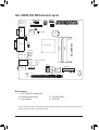
GA-J1900N-D3V Motherboard Layout
Box Contents
5 GA-J1900N-D3V motherboard
5 Motherboard driver disk 5 Two SATA cables
5 User's Manual 5 I/O Shield
The box contents above are for reference only and the actual items shall depend on the product package you obtain.
The box contents are subject to change without notice.
KB_MS
SYS_FAN
Intel
®
J1900 SoC
AUDIO
SODIMM_1
BAT
ATX_12V
CODEC
PCIe to PCI
Bridge
M_BIOS
B_BIOS
COMA
COMB
iTE
®
Super I/O
USB30_LAN1
GA-J1900N-D3V
F_PANEL
F_USB
0 1
ATX
VGA
DVI
LPT
CI
F_AUDIO
CPU_FAN
PCI
Realtek
®
GbE LAN
SATA2
SPDIF_O
CLR_CMOS
DEBUG_PORT
USB30_LAN2
SODIMM_2
MINI PCIE
Realtek
®
GbE LAN
Renesas
®
uPD720210
BUZZER
- 4 -

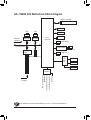
GA-J1900N-D3V Motherboard Block Diagram
Fordetailedproductinformation/limitation(s),referto"1-2ProductSpecications."
Line-Out (Front Speaker Out)
MIC (Center/Subwoofer
Speaker Out)
Line-In (Rear Speaker Out)
PS/2 KB/Mouse
Intel
®
J1900 SoC
Dual BIOS
DDR3L 1333 MHz
Dual Channel Memory
LPC Bus
LPT
2 USB 2.0/1.1
PCI Express Bus
PCIe CLK
(100 MHz)
iTE
®
Super
I/O
x1
LAN
RJ45
Realtek
®
GbE LAN
DVI-D
D-Sub
x1
1 PCI
PCI CLK
(33 MHz)
PCIe to PCI
Bridge
2 SATA 3Gb/s
S/PDIF Out
CODEC
COM
x1
LAN
RJ45
Realtek
®
GbE LAN
4 USB 3.0/2.0
Renesas
®
uPD720210 Hub
x1
Mini PCI Express x1
- 5 -

- 6 -
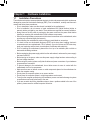
Chapter 1 Hardware Installation
1-1 Installation Precautions
The motherboard contains numerous delicate electronic circuits and components which can become
damaged as a result of electrostatic discharge (ESD). Prior to installation, carefully read the user's
manual and follow these procedures:
• Prior to installation, make sure the chassis is suitable for the motherboard.
• Prior to installation, do not remove or break motherboard S/N (Serial Number) sticker or
warranty sticker provided by your dealer. These stickers are required for warranty validation.
• Always remove the AC power by unplugging the power cord from the power outlet before
installing or removing the motherboard or other hardware components.
• When connecting hardware components to the internal connectors on the motherboard, make
sure they are connected tightly and securely.
• When handling the motherboard, avoid touching any metal leads or connectors.
• It is best to wear an electrostatic discharge (ESD) wrist strap when handling electronic
components such as a motherboard, CPU or memory. If you do not have an ESD wrist strap,
keepyourhandsdryandrsttouchametalobjecttoeliminatestaticelectricity.
• Prior to installing the motherboard, please have it on top of an antistatic pad or within an
electrostatic shielding container.
• Before unplugging the power supply cable from the motherboard, make sure the power supply
has been turned off.
• Before turning on the power, make sure the power supply voltage has been set according to
the local voltage standard.
• Before using the product, please verify that all cables and power connectors of your hardware
components are connected.
• To prevent damage to the motherboard, do not allow screws to come in contact with the
motherboard circuit or its components.
• Make sure there are no leftover screws or metal components placed on the motherboard or
within the computer casing.
• Do not place the computer system on an uneven surface.
• Do not place the computer system in a high-temperature environment.
• Turning on the computer power during the installation process can lead to damage to system
components as well as physical harm to the user.
• If you are uncertain about any installation steps or have a problem related to the use of the
product,pleaseconsultacertiedcomputertechnician.

- 7 -
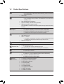
1-2 ProductSpecications
CPU Built in with an Intel
®
Celeron
®
Quad-Core J1900 SoC (2.0 GHz)
* Do not disassemble the onboard SoC and the heatsink by yourself to avoid damage
to these components.
2 MB Cache
Memory 2 x 1.35V DDR3L DIMM sockets supporting up to 8 GB of system memory
* If only one DDR3L memory module is to be installed, be sure to install it in the
SODIMM_1 socket.
Dual channel memory architecture
Support for DDR3L 1333 MHz memory modules
Support for non-ECC memory modules
(Go to GIGABYTE's website for the latest supported memory speeds and memory
modules.)
Onboard
Graphics
Integrated in the SoC:
- 1 x D-Sub port, supporting a maximum resolution of 2560x1600
- 1 x DVI-D port, supporting a maximum resolution of 1920x1080
* The DVI-D port does not support D-Sub connection by adapter.
Audio
Realtek
®
ALC887 codec
High Denition Audio
2/4/5.1/7.1-channel
* To congure 7.1-channel audio, you have to use an HD front panel audio module
and enable the multi-channel audio feature through the audio driver.
Support for S/PDIF Out
LAN 2 x Realtek
®
GbE LAN chips (10/100/1000 Mbit)
Expansion Slots
1 x PCI slot
1 x Mini PCI Express x1 slot
* This socket does not support USB Bluetooth signals.
(The Mini PCI Express slot conforms to PCI Express 2.0 standard.)
Storage Interface Integrated in the SoC:
- 2 x SATA 3Gb/s connectors
USB
Integrated in the SoC:
- 2 x USB 2.0/1.1 ports (available through the internal USB header)
SoC + Renesas
®
uPD720210 USB 3.0 Hub:
- 4 x USB 3.0/2.0 ports on the back panel
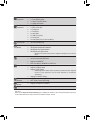
Internal
Connectors
1 x 24-pin ATX main power connector
1 x 4-pin ATX 12V power connector
2 x SATA 3Gb/s connectors
1 x CPU fan header
1 x system fan header
1 x front panel header
1 x front panel audio header
1 x S/PDIF Out header
1 x USB 2.0/1.1 header

- 8 -
Internal
Connectors
1 x parallel port header
1 x Clear CMOS jumper
1 x chassis intrusion header
1 x debug card header
Back Panel
Connectors
1 x PS/2 keyboard port
1 x PS/2 mouse port
1 x D-Sub port
1 x DVI-D port
2 x serial ports
4 x USB 3.0/2.0 ports
2 x RJ-45 ports
3 x audio jacks (Line In, Line Out, Mic In)
I/O Controller iTE
®
I/O Controller Chip
Hardware
Monitor
System voltage detection
CPU/System temperature detection
CPU/System fan speed detection
CPU/System fan speed control
* Whether the fan speed control function is supported will depend on the cooler you
install.
BIOS 2 x 64 Mbit ash
Use of licensed AMI UEFI BIOS
Support for DualBIOS
™
PnP 1.0a, DMI 2.0, SM BIOS 2.6, ACPI 2.0a
Unique Features Support for @BIOS
Support for Xpress Install
Support for APP Center
* Available applications in APP Center may differ by motherboard model. Supported
functions of each application may also differ depending on motherboard
specications.
Support for ON/OFF Charge
Bundled
Software
Norton
®
Internet Security (OEM version)
Intel
®
Smart Connect Technology
Operating
System
Support for Windows 8.1/8 64-bit
Form Factor
Mini-ITX Form Factor; 17.0cm x 17.0cm
* GIGABYTE reserves the right to make any changes to the product specications and product-related information without
prior notice.
* Please visit the
Support & Downloads\Utility
page on GIGABYTE's website to check the supported operating system(s)
for the software listed in the "Unique Features" and "Bundled Software" columns.

- 9 -
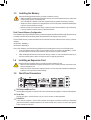
1-3 Installing the Memory
Read the following guidelines before you begin to install the memory:
• Make sure that the motherboard supports the memory. It is recommended that memory of the same
capacity, brand, speed, and chips be used.
(Go to GIGABYTE's website for the latest supported memory speeds and memory modules.)
• Always turn off the computer and unplug the power cord from the power outlet before installing the
memory to prevent hardware damage.
• Memory modules have a foolproof design. A memory module can be installed in only one direction.
If you are unable to insert the memory, switch the direction.
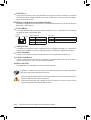
DualChannelMemoryConguration
This motherboard provides two DDR3L memory sockets and supports Dual Channel Technology. After the memory
isinstalled,theBIOSwillautomaticallydetectthespecicationsandcapacityofthememory.
The two DDR3L memory sockets are divided into two channels and each channel has one memory socket as
following:
Channel A: SODIMM_1
Channel B: SODIMM_2
Due to SoC limitations, read the following guidelines before installing the memory in Dual Channel mode.
1. If only one DDR3L memory module is to be installed, be sure to install it in the SODIMM_1 socket,
and Dual Channel mode cannot be enabled if only one memory module is installed.
2. When enabling Dual Channel mode with two memory modules, it is recommended that memory of
the same capacity, brand, speed, and chips be used for optimum performance.
1-4 Installing an Expansion Card
Read the following guidelines before you begin to install an expansion card:
• Make sure the motherboard supports the expansion card. Carefully read the manual that came
with your expansion card.
• Always turn off the computer and unplug the power cord from the power outlet before installing an
expansion card to prevent hardware damage.
1-5 Back Panel Connectors
PS/2 Keyboard/Mouse Port
Use the upper port (green) to connect a PS/2 mouse and the lower port (purple) to connect a PS/2 keyboard.
Serial Port
Use the serial port to connect devices such as a mouse, modem or other peripherals.
D-Sub Port
The D-Sub port supports a 15-pin D-Sub connector and supports a maximum resolution of 2560x1600
(the actual resolutions supported depend on the monitor being used). Connect a monitor that supports
D-Sub connection to this port.

- 10 -
Tocongure7.1-channelaudio,youhavetouseanHDfrontpanelaudiomoduleandenablethe
multi-channel audio feature through the audio driver.
Line In Jack (Blue)
The line out jack. Use this audio jack for line in devices such as an optical drive, walkman, etc.
Line Out Jack (Green)
The line out jack. Use this audio jack for a headphone or 2-channel speaker. This jack can be used to
connectfrontspeakersina4/5.1/7.1-channelaudioconguration.
Mic In Jack (Pink)
The default Mic in jack. Microphones must be connected to this jack.
• Whenremovingthecableconnectedtoabackpanelconnector,rstremovethecablefromyour
device and then remove it from the motherboard.
• When removing the cable, pull it straight out from the connector. Do not rock it side to side to
prevent an electrical short inside the cable connector.
RJ-45 LAN Port
The Gigabit Ethernet LAN port provides Internet connection at up to 1 Gbps data rate. The following
describes the states of the LAN port LEDs.
USB 3.0/2.0 Port
TheUSB3.0portsupportstheUSB3.0specicationandiscompatibletotheUSB2.0/1.1specication.
UsethisportforUSBdevicessuchasaUSBkeyboard/mouse,USBprinter,USBashdriveandetc.
DualDisplayCongurationsfortheOnboardGraphics:
Dual-displaycongurationsaresupportedafteryouinstallmotherboarddriversinOS,butnotduringthe
BIOS Setup or POST process.
(Note) The DVI-D port does not support D-Sub connection by adapter.
DVI-D Port
(Note)
TheDVI-DportconformstotheDVI-Dspecicationandsupportsamaximumresolutionof1920x1080
(the actual resolutions supported depend on the monitor being used). Connect a monitor that supports
DVI-D connection to this port.
Activity LED
Connection/
Speed LED
LAN Port
Activity LED:Connection/Speed LED:
State Description
Orange 1 Gbps data rate
Green 100 Mbps data rate
Off 10 Mbps data rate
State Description
Blinking Data transmission or receiving is occurring
Off No data transmission or receiving is occurring

- 11 -
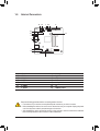
1-6 Internal Connectors
Read the following guidelines before connecting external devices:
• First make sure your devices are compliant with the connectors you wish to connect.
• Before installing the devices, be sure to turn off the devices and your computer. Unplug the power
cord from the power outlet to prevent damage to the devices.
• After installing the device and before turning on the computer, make sure the device cable has
been securely attached to the connector on the motherboard.
1) ATX_12V
2) ATX
3) CPU_FAN
4) SYS_FAN
5) SATA2 0/1
6) F_PANEL
7) F_AUDIO
8) SPDIF_O
9) F_USB
10) LPT
11) BAT
12) CLR_CMOS
13) CI
14) DEBUG_PORT
11
61
3
2
7
8
5
4
1410
13
12
9

- 12 -
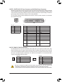
1/2) ATX_12V/ATX (2x2 12V Power Connector and 2x12 Main Power Connector)
With the use of the power connector, the power supply can supply enough stable power to all the components
onthemotherboard.Beforeconnectingthepowerconnector,rstmakesurethepowersupplyisturned
off and all devices are properly installed. The power connector possesses a foolproof design. Connect the
power supply cable to the power connector in the correct orientation.
The 12V power connector mainly supplies power to the CPU. If the 12V power connector is not connected,
the computer will not start.
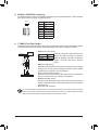
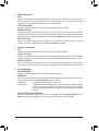
3/4) CPU_FAN/SYS_FAN (Fan Headers)
The motherboard has a 3-pin CPU fan header (CPU_FAN) and a 4-pin system fan header (SYS_FAN).
Most fan headers possess a foolproof insertion design. When connecting a fan cable, be sure to connect it
in the correct orientation (the black connector wire is the ground wire). The speed control function requires
the use of a fan with fan speed control design. For optimum heat dissipation, it is recommended that a
system fan be installed inside the chassis.
• Be sure to connect fan cables to the fan headers to prevent your CPU and system from
overheating. Overheating may result in damage to the CPU or the system may hang.
• Thesefanheadersarenotcongurationjumperblocks.Donotplaceajumpercapontheheaders.
CPU_FAN:
Pin No. Denition
1 GND
2 Speed Control
3 Sense
SYS_FAN:
Pin No. Denition
1 GND
2 Speed Control
3 Sense
4 VCC
CPU_FAN
1
SYS_FAN
DEBUG
PORT
G.QBOFM
1
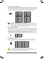
ATX_12V:
Pin No. Denition
1 GND
2 GND
3 +12V
4 +12V
DEBUG
PORT
G.QBOFM
ATX
ATX:
Pin No. Denition Pin No. Denition
1 3.3V 13 3.3V
2 3.3V 14 -12V
3 GND 15 GND
4 +5V 16 PS_ON (soft On/Off)
5 GND 17 GND
6 +5V 18 GND
7 GND 19 GND
8 Power Good 20 -5V
9 5VSB (stand by +5V) 21 +5V
10 +12V 22 +5V
11 +12V (Only for 2x12-pin
ATX)
23 +5V (Only for 2x12-pin ATX)
12 3.3V (Only for 2x12-pin
ATX)
24 GND (Only for 2x12-pin
ATX)
13 24
1 12
ATX_12V
1
3
2
4

- 13 -
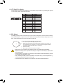
Pin No. Denition
1 GND
2 TXP
3 TXN
4 GND
5 RXN
6 RXP
7 GND
5) SATA2 0/1 (SATA 3Gb/s Connectors)
The SATA connectors conform to SATA 3Gb/s standard and are compatible with SATA 1.5Gb/s standard.
Each SATA connector supports a single SATA device.
0 1
DEBUG
PORT
G.QBOFM
7
1
SATA2
DEBUG
PORT
G.QBOFM
7
1
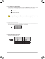
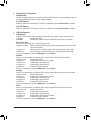
6) F_PANEL (Front Panel Header)
Connect the power switch, reset switch, and system status indicator on the chassis to this header according
to the pin assignments below. Note the positive and negative pins before connecting the cables.
• PW (Power Switch, Red):
Connectstothepowerswitchonthechassisfrontpanel.Youmaycongure
the way to turn off your system using the power switch (refer to Chapter
2, "BIOS Setup," "Chipset," for more information).
• HD (Hard Drive Activity LED, Blue):
Connects to the hard drive activity LED on the chassis front panel. The
LED is on when the hard drive is reading or writing data.
• RES (Reset Switch, Green):
Connects to the reset switch on the chassis front panel. Press the reset
switch to restart the computer if the computer freezes and fails to perform
a normal restart.
• NC (Purple): No connection.
• PLED (Power LED, Yellow):
System Status LED
S0 On
S3/S4/S5 Off
Connects to the power status indicator on the
chassis front panel. The LED is on when the
system is operating. The LED is off when the
system is in S3/S4 sleep state or powered
off (S5).
The front panel design may differ by chassis. A front panel module mainly consists of power switch, reset switch,
power LED, hard drive activity LED and etc. When connecting your chassis front panel module to this header,
make sure the wire assignments and the pin assignments are matched correctly.
1
2
9
10
NC
PLED-
PW-
PLED+
PW+
HD-
RES+
HD+
RES-
Power LED
Power Switch
Hard Drive
Activity LED
Reset Switch

- 14 -
7) F_AUDIO (Front Panel Audio Header)
ThefrontpanelaudioheadersupportsIntelHighDenitionaudio(HD)andAC'97audio.Youmayconnect
your chassis front panel audio module to this header. Make sure the wire assignments of the module
connector match the pin assignments of the motherboard header. Incorrect connection between the module
connector and the motherboard header will make the device unable to work or even damage it.
For HD Front Panel Audio: For AC'97 Front Panel Audio:
• The front panel audio header supports HD audio by default.
• Audio signals will be present on both of the front and back panel audio connections simultaneously.
• Some chassis provide a front panel audio module that has separated connectors on each wire
instead of a single plug. For information about connecting the front panel audio module that has
different wire assignments, please contact the chassis manufacturer.
Pin No. Denition
1 MIC2_L
2 GND
3 MIC2_R
4 -ACZ_DET
5 LINE2_R
6 GND
7 FAUDIO_JD
8 No Pin
9 LINE2_L
10 GND
Pin No. Denition
1 MIC
2 GND
3 MIC Power
4 NC
5 Line Out (R)
6 NC
7 NC
8 No Pin
9 Line Out (L)
10 NC
2
10
1
9
8) SPDIF_O (S/PDIF Out Header)
This header supports digital S/PDIF Out and connects a S/PDIF digital audio cable (provided by expansion
cards) for digital audio output from your motherboard to certain expansion cards like graphics cards and
sound cards. For example, some graphics cards may require you to use a S/PDIF digital audio cable for
digital audio output from your motherboard to your graphics card if you wish to connect an HDMI display
to the graphics card and have digital audio output from the HDMI display at the same time.
For information about connecting the S/PDIF digital audio cable, carefully read the manual for your expansion
card.
Pin No. Denition
1 SPDIFO
2 GND
2
9) F_USB (USB 2.0/1.1 Header)
TheheaderconformstoUSB2.0/1.1specication.EachUSBheadercanprovidetwoUSBportsviaan
optional USB bracket. For purchasing the optional USB bracket, please contact the local dealer.
Pin No. Denition Pin No. Denition
1 Power (5V) 6 USB DY+
2 Power (5V) 7 GND
3 USB DX- 8 GND
4 USB DY- 9 No Pin
5 USB DX+ 10 NC
• Do not plug the IEEE 1394 bracket (2x5-pin) cable into the USB 2.0/1.1 header.
• Prior to installing the USB bracket, be sure to turn off your computer and unplug the power cord
from the power outlet to prevent damage to the USB bracket.
10
1
9
1

- 15 -
11) BAT (Battery)
Thebatteryprovidespowertokeepthevalues(suchasBIOScongurations,date,andtimeinformation)
in the CMOS when the computer is turned off. Replace the battery when the battery voltage drops to a low
level, or the CMOS values may not be accurate or may be lost.
You may clear the CMOS values by removing the battery:
1. Turn off your computer and unplug the power cord.
2. Gently remove the battery from the battery holder and wait for one minute. (Or
use a metal object like a screwdriver to touch the positive and negative terminals
of the battery holder, making them short for 5 seconds.)
3. Replace the battery.
4. Plug in the power cord and restart your computer.
• Always turn off your computer and unplug the power cord before replacing the battery.
• Replace the battery with an equivalent one. Danger of explosion if the battery is replaced with
an incorrect model.
• Contact the place of purchase or local dealer if you are not able to replace the battery by yourself
or uncertain about the battery model.
• When installing the battery, note the orientation of the positive side (+) and the negative side (-)
of the battery (the positive side should face up).
• Used batteries must be handled in accordance with local environmental regulations.
10) LPT (Parallel Port Header)
The LPT header can provide one parallel port via an optional LPT port cable. For purchasing the optional
LPT port cable, please contact the local dealer.
Pin No. Denition Pin No. Denition
1 STB- 14 GND
2 AFD- 15 PD6
3 PD0 16 GND
4 ERR- 17 PD7
5 PD1 18 GND
6 INIT-
19
ACK-
7 PD2 20 GND
8 SLIN- 21 BUSY
9 PD3 22 GND
10 GND 23 PE
11
PD4 24
No Pin
12 GND 25 SLCT
13 PD5 26 GND
DEBUG
PORT
G.QBOFM
1
2
25
26

- 16 -
12) CLR_CMOS (Clear CMOS Jumper)
UsethisjumpertocleartheBIOScongurationandresettheCMOSvaluestofactorydefaults.Toclear
the CMOS values, use a metal object like a screwdriver to touch the two pins for a few seconds.
• Always turn off your computer and unplug the power cord from the power outlet before clearing the CMOS values.
• After system restart, go to BIOS Setup to load factory defaults (select Load Optimized Defaults) or manually
conguretheBIOSsettings(refertoChapter2,"BIOSSetup,"forBIOScongurations).
Open: Normal
Short: Clear CMOS Values
13) CI (Chassis Intrusion Header)
This motherboard provides a chassis detection feature that detects if the chassis cover has been removed.
This function requires a chassis with chassis intrusion detection design.
14) DEBUG PORT (Debug Card Header)
This header can connect a debug card.
1
Pin No. Denition
1 Signal
2 GND
Pin No. Denition Pin No. Denition
1 No Pin 7 LAD3
2 GND 8 -LFRAME
3 VCC3 9 -PFMRST
4 LAD0 10 DB CLK
5 LAD1 11 DB_P_SENSOR
6 LAD2 12 NC
DEBUG
PORT
G.QBOFM
2
1
12
11

- 17 -
BIOS (Basic Input and Output System) records hardware parameters of the system in the CMOS on the
motherboard. Its major functions include conducting the Power-On Self-Test (POST) during system startup,
saving system parameters and loading operating system, etc. BIOS includes a BIOS Setup program that allows
theusertomodifybasicsystemcongurationsettingsortoactivatecertainsystemfeatures.
When the power is turned off, the battery on the motherboard supplies the necessary power to the CMOS to
keepthecongurationvaluesintheCMOS.
To access the BIOS Setup program, press the <Delete> key during the POST when the power is turned on.
To upgrade the BIOS, use the GIGABYTE @BIOS utility, which is a Windows-based utility that searches and
downloads the latest version of BIOS from the Internet and updates the BIOS.
Chapter 2 BIOS Setup
• BecauseBIOSashingispotentiallyrisky,ifyoudonotencounterproblemsusingthecurrent
versionofBIOS,itisrecommendedthatyounotashtheBIOS.ToashtheBIOS,doitwith
caution.InadequateBIOSashingmayresultinsystemmalfunction.
• It is recommended that you not alter the default settings (unless you need to) to prevent system
instability or other unexpected results. Inadequately altering the settings may result in system's
failure to boot. If this occurs, try to clear the CMOS values and reset the board to default values.
(Refer to the "Restore Defaults" section in this chapter or introductions of the battery/clear CMOS
jumper in Chapter 1 for how to clear the CMOS values.)
2-1 Startup Screen
The following startup Logo screen will appear when the computer boots.

- 18 -
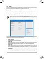
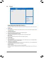
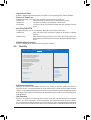
2-2 Main
Once you enter the BIOS Setup program, the Main Menu (as shown below) appears on the screen. Use arrow
keys to move among the items and press <Enter> to accept or enter a sub-menu.
Main Menu Help
The on-screen description of a highlighted setup option is displayed on the bottom line of the Main Menu.
Submenu Help
While in a submenu, press <F1> to display a help screen (General Help) of function keys available for the menu.
Press <Esc> to exit the help screen. Help for each item is in the Item Help block on the right side of the submenu.
(Sample BIOS Version: F1a)
•
When the system is not stable as usual, select the Restore Defaults item to set your system to its
defaults.
•
The BIOS Setup menus described in this chapter are for reference only and may differ by BIOS
version.
This section provides information on your motherboard model and BIOS version. You can also select the default
language used by the BIOS and manually set the system time.
• System Language
Selects the default language used by the BIOS.
• System Date
Sets the system date. The date format is week (read-only), month, date, and year. Use <Tab> to switch
betweentheMonth,Date,andYeareldsandusethe<+>or<->keytosetthedesiredvalue.
• System Time
Sets the system time. The time format is hour, minute, and second. For example, 1 p.m. is 13:0:0. Use
<Tab>toswitchbetweentheHour,Minute,andSecondeldsandusethe<+>or<->keytosetthedesired
value.
• Access Level
Displays the current access level depending on the type of password protection used. (If no password is
set, the default will display as Administrator.) The Administrator level allows you to make changes to all
BIOS settings; the User level only allows you to make changes to certain BIOS settings but not all.
Aptio Setup Utility - Copyright (C) 2013 American Megatrends, Inc.
BootAdvanced Save & ExitSecurityChipset
Aptio Setup Utility - Copyright (C) 2013 American Megatrends, Inc.
Main
BIOS Information
BIOS ID 8A05AG06
Project Nate J1900N-D3V
BIOS Version F1a
Build Date and Time 01/07/2014 21:17:27
Memory Information
Total Memory 4096 MB (LPDDR3)
System Language [English]
System Date [Sun 01/07/2014]
System Time [4:46:46 PM]
Access Level
gf: Select Screen
hi: Select Item
Enter: Select
+/-: Change Opt.
F1: General Help
F2: Previous Values
F3: Optimized Defaults
F4: Save & Exit
ESC: Exit

- 19 -
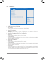
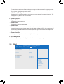
2-3 Advanced
` Intel(R) Smart Connect Technology
& ISCT Support
Enables or disables Intel
®
Smart Connect Technology. (Default: Disabled)
` SuperIOConguration
ThissectionprovidesinformationonthesuperI/Ochipandallowsyoutoconguretheserialportand
parallel port.
` SerialPort0Conguration/SerialPort1Conguration
& Serial Port
Enables or disables the onboard serial ports. (Default: Enabled)
& Change Settings
AllowsyoutocongurationtheIRQsettingsfortheserialports.ThisitemiscongurableonlywhenSerial
Port is set to Enabled. (Default: Auto)
` ParallelPortConguration
& Parallel Port
Enables or disables the onboard parallel port. (Default: Enabled)
& Change Settings
AllowsyoutocongurationtheIRQsettingsfortheparallelport.ThisitemiscongurableonlywhenParallel
Port is set to Enabled. (Default: Auto)
& Device Mode
Selectsanoperatingmodefortheonboardparallel(LPT)port.ThisitemiscongurableonlywhenParallel
Port is set to Enabled. Options are: Standard Parallel Port Mode (Default), EPP Mode (Enhanced Parallel
Port), ECP Mode (Extended Capabilities Port), EPP Mode & ECP Mode.
Aptio Setup Utility - Copyright (C) 2013 American Megatrends, Inc.
Aptio Setup Utility - Copyright (C) 2013 American Megatrends, Inc.
Main
` Intel(R) Smart Connect Technology
` SuperIOConguration
` H/W Monitor
` CPUConguration
` PPMConguration
` ThermalConguration
` IDEConguration
` NetworkStackConguration
` CSMConguration
` USBConguration
` Realtek PCIe GBE Family Controller (MAC:00:00:00:00:00:03)
` Realtek PCIe GBE Family Controller (MAC:00:00:00:00:00:03)
gf: Select Screen
hi: Select Item
Enter: Select
+/-: Change Opt.
F1: General Help
F2: Previous Values
F3: Optimized Defaults
F4: Save & Exit
ESC: Exit
Boot Save & ExitSecurityChipsetAdvanced

- 20 -
& ErP
Determines whether to let the system consume least power in S5 (shutdown) state. (Default: Disabled)
Note: When this item is set to Enabled, the following functions will become unavailable: PME event wake
up, power on by mouse, power on by keyboard, and wake on LAN.
& Case Open
Displays the detection status of the chassis intrusion detection device attached to the motherboard CI
header.Ifthesystemchassiscoverisremoved,thiseldwillshow"Open",otherwiseitwillshow"Close."
To clear the chassis intrusion status record, set Reset Case Open Status to Enabled, save the settings
to the CMOS, and then restart your system.
& Reset Case Open Status
Disabled Keeps or clears the record of previous chassis intrusion status. (Default)
Enabled Clears the record of previous chassis intrusion status and the Case Openeldwillshow
"Close" at next boot.
` H/W Monitor
& CPU Temperature (DTS)/System Temperature
Displays current CPU/system temperature.
& CPU/System Fan Speed
Displays current CPU/system fan speed.
& Vcore/VCC3/+12V/VCC/CPU_VAXG/3VDUAL/DDR1_35VIO
Displays the current system voltages.
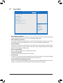
` CPUConguration
` Socket 0 CPU Information
This section provides information on your CPU, frequency, and cache memory.
& Active Processor Cores
Allows you to determine whether to enable all CPU cores. (Default: All)
& Limit CPUID Maximum
Allows you to determine whether to limit CPUID maximum value. Set this item to Disabled for Windows XP
operating system; set this item to Enabled for legacy operating system such as Windows NT4.0. (Default:
Disabled)
& Execute Disable Bit
Enables or disables Intel
®
Execute Disable Bit function. This function may enhance protection for the
computer, reducing exposure to viruses and malicious buffer overowattacks when working with its
supporting software and system. (Default: Enabled)
& Hardware Prefetcher
Enables or disables L2 Cache Hardware Prefetcher. (Default: Enabled)
& Adjacent Cache Line Prefetch
Enables or disables L2 prefetching of adjacent cache lines. (Default: Enabled)
& Intel Virtualization
Enables or disables Intel
®
Virtualization Technology. Virtualization enhanced by Intel
®
Virtualization
Technology will allow a platform to run multiple operating systems and applications in independent partitions.
With virtualization, one computer system can function as multiple virtual systems. (Default: Enabled)
& Power Technology
AllowsyoutocongureIntel
®
powermanagementfeatures.(Default:EnergyEfcient)
Page is loading ...
Page is loading ...
Page is loading ...
Page is loading ...
Page is loading ...
Page is loading ...
Page is loading ...
Page is loading ...
Page is loading ...
Page is loading ...
Page is loading ...
Page is loading ...
-
 1
1
-
 2
2
-
 3
3
-
 4
4
-
 5
5
-
 6
6
-
 7
7
-
 8
8
-
 9
9
-
 10
10
-
 11
11
-
 12
12
-
 13
13
-
 14
14
-
 15
15
-
 16
16
-
 17
17
-
 18
18
-
 19
19
-
 20
20
-
 21
21
-
 22
22
-
 23
23
-
 24
24
-
 25
25
-
 26
26
-
 27
27
-
 28
28
-
 29
29
-
 30
30
-
 31
31
-
 32
32


Gigabyte GA-J1900N-D3V (rev. 1.0) User manual
- Category
- Motherboards
- Type
- User manual
Ask a question and I''ll find the answer in the document
Finding information in a document is now easier with AI
Related papers
-
Gigabyte GA-C1007UN-D User manual
-
Gigabyte GA-E3800N Owner's manual
-
-
Gigabyte GA-C1037UN-L User manual
-
-
-
-
-
-
Gigabyte GA-H61MA-D3V Owner's manual
Other documents
-
Renesas PCIe USB 3.0 Controller Card User manual
-
 AmazonBasics HU2W70E1 User manual
-
AmazonBasics HU2W70E1 User manual
-
Vantec UGT-PC345 User manual
-
Lanner FW-7543 User manual
-
 Premio RCO-1000-J1900-10G User manual
-
Kam SR Sample Receiver User manual
-
SilverStone EC04-E Owner's manual
-
Cybernet ZPC-D5X Datasheet

