Page is loading ...

361T
B/W TRANSMISSION
DENSITOMETER
Operation Manual

361T
DENSITOMETER
Federal Communications Commission Notice
This equipment has been tested and found to comply with the limits for a Class A digital
device, pursuant to Part 15 of the FCC Rules. These limits are designed to provide
reasonable protection against harmful interference when the equipment is operated in a
commercial environment. This equipment generates, uses, and can radiate radio frequency
energy and, if not installed and used in accordance with the instruction manual, may cause
harmful interference to radio communications. Operation of this equipment in a residential
area is likely to cause harmful interference in which case the user will be required to
correct the interference at his own expense.
NOTE: Shielded interface cables must be used in order to maintain compliance with the
desired FCC and European emission requirements.
Industry Canada Compliance Statement
This Class A digital apparatus complies with Canadian ICES-003.
Cet appareil numérique de la classe A est conforme à la norme NMB-003 du Canada.
AVERTISSEMENT : Des câbles d'interface blindés doivent être utilisés afin de se
conformer aux règlements européens et FCC (USA) sur l'émission.
CE DECLARATION
Manufacturer's Name: X-Rite, Incorporated
Manufacturer's Address: X-Rite, Incorporated
Siemensstraße 12b
63263 Neu-Isenburg • Germany
Phone: +49 (0) 61 02-79 57-0
Fax: +49 (0) 61 02 -79 57-57
Model Name: Densitometer
Model No.: 361
Directive(s) Conformance: EMC 89/336/EEC LVD 73/23/EEC
RoHS/WEEE
X-Rite products meet the Restriction of Hazardous Substances (RoHS)
Directive 2002/95/EC and European Union – Waste Electrical and
Electronic Equipment (WEEE) Directive 2002/96/EC. Please refer to
www.xrite.com
for more information on X-Rite’s compliance with the
RoHS/WEEE directives.

361T
DENSITOMETER
iii
Table of Contents
1. Overview and Setup.......................................................................... 1-1
Instrument Description....................................................................................1-1
Features...........................................................................................................1-3
Unpack and Inspect.........................................................................................1-3
Apply Power and Display Angle Adjustment.................................................1-4
Display (EL) Backlighting..............................................................................1-4
2. User Interface .................................................................................... 2-1
Key Description ..............................................................................................2-1
FUNCTION ...............................................................................................2-1
COLOR ......................................................................................................2-1
ZERO..........................................................................................................2-1
Function Selection ..........................................................................................2-2
Color Selection ...............................................................................................2-3
Reference and Base Entry...............................................................................2-4
Density Reference Entry Via Keyboard......................................................2-4
Density Reference Entry Via Measurement................................................2-4
Base Entry...................................................................................................2-5
Measurement Procedure - General..................................................................2-5
Display Messages ...........................................................................................2-5
311 Emulation.................................................................................................2-6
3. Measurement Procedures ................................................................ 3-1
Density Function.............................................................................................3-1
DENSITY MEASUREMENT ....................................................................3-1
DENSITY DIFFERENCE MEASUREMENT ...........................................3-1
+DOT Function...............................................................................................3-1
+DOT MEASUREMENT...........................................................................3-1
-DOT Function................................................................................................3-2
-DOT MEASUREMENT............................................................................3-2
Sequence (Disabled from factory) ..................................................................3-2
4. Calibration ......................................................................................... 4-1
General Information........................................................................................4-1
Frequency of Calibration ............................................................................4-1
Density Calibration Check..........................................................................4-1
Density Calibration Procedure........................................................................4-1
Dot Area Calibration Procedure......................................................................4-2
N-Factor Adjustment Procedure .....................................................................4-3
Quick CAL™ Procedure.................................................................................4-4

361T
DENSITOMETER
iv
5.
Mode Selection.................................................................................. 5-1
General Information........................................................................................5-1
x10 ON/OFF ...................................................................................................5-1
I/O Port Selection............................................................................................5-2
Setting the Sequence Structure .......................................................................5-4
Read Lamp ON/OFF.......................................................................................5-6
6. Serial Interface .................................................................................. 6-1
Interconnect and Definition ............................................................................6-1
Serial Output...................................................................................................6-2
Serial Input Commands...................................................................................6-2
Instruction Format...........................................................................................6-3
Internal RAM Data Addresses ........................................................................6-9
External RAM Data Addresses.....................................................................6-10
7. Maintenance ...................................................................................... 7-1
General............................................................................................................7-1
Exterior Cleaning............................................................................................7-1
Aperture Replacement & Cleaning .................................................................7-2
APERTURE REPLACEMENT..................................................................7-2
APERTURE CLEANING...........................................................................7-2
Beam Splitter Cleaning...................................................................................7-3
Optics Cleaning...............................................................................................7-3
Lamp Replacement .........................................................................................7-4
ALIGNMENT CHECK ..............................................................................7-5
Fuse Replacement...........................................................................................7-7
8. Appendix............................................................................................ 8-1
Technical Specifications .................................................................................8-1
Optional Equipment........................................................................................8-3

361T
DENSITOMETER
v
Proprietary Notice
The information contained in this manual is derived from patent and proprietary
data of X-Rite, Incorporated. This manual has been prepared solely for the
purpose of assisting in the use and general maintenance of this instrument.
The contents of this manual are the property of X-Rite, Incorporated and
are copyrighted. Any reproduction in whole or part is strictly prohibited.
Publication of this information does not imply any rights to reproduce or use this
manual for any purpose other than installing, operating, or maintaining this
instrument. No part of this manual may be reproduced, transcribed, transmitted,
stored in a retrieval system, or translated into any language or computer
language, in any form or by any means, electronic, magnetic, mechanical,
optical, manual, or otherwise, without the prior written permission of an officer
of X-Rite, Incorporated.
This instrument may be covered by one or more patents. Refer to the instrument
for actual patent numbers.
Copyright © 2007 by X-Rite, Incorporated
“ALL RIGHTS RESERVED”
X-Rite® is a registered trademark of X-Rite, Incorporated. All other logos, brand names,
and product names mentioned are the properties of their respective holders.
Warranty Information
X-Rite, Incorporated (“X-Rite”) warrants each instrument manufactured to be
free of defects in material and workmanship (excluding battery pack) for a
period of 12 months. This warranty shall be fulfilled by the repair or
replacement, at the option of X-Rite, of any part or parts, free of charge
including labor, F.O.B. its factory or authorized service center.
This warranty shall be voided by any repair, alteration, or modification, by
persons other than employees of X-Rite, or those expressly authorized by X-Rite
to perform repairs, and by any abuse, misuse, or neglect of the product, or by use
not in accordance with X-Rite’s published instructions.
X-Rite reserves the right to make changes in design and /or improvements to its
products without any obligation to include these changes in any products
previously manufactured. Correction of defects by repair or replacement shall
constitute fulfillment of all warranty obligations on the part of X-Rite.
THIS WARRANTY IS EXPLICITLY IN LIEU OF ANY OTHER
EXPRESSED OR IMPLIED WARRANTIES, INCLUDING ANY IMPLIED
WARRANTY OF MERCHANTABILITY OR FITNESS FOR ANY
PARTICULAR PURPOSE. THIS WARRANTY OBLIGATION IS LIMITED
TO REPAIR OR REPLACEMENT OF THE UNIT RETURNED TO X-RITE
OR AN AUTHORIZED SERVICE CENTER FOR THAT PURPOSE.

361T
DENSITOMETER
vi
This agreement shall be interpreted in accordance with the laws of the State of
Michigan and jurisdiction and venue shall lie with the courts of Michigan as
selected by X-Rite, Incorporated.

361T
DENSITOMETER
1-1
1. Overview and Setup
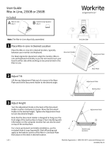
Instrument Description
The X-Rite 361T is a B/W Transmission densitometer designed to meet
the quality control needs of the Graphic Arts industry. Your 361T has
been integrated with components from the leading edges of technology,
which X-Rite has been internationally recognized for.
[1] DISPLAY - is an 8-character Liquid Crystal Display.
[2] DISPLAY CONTRAST ADJUSTMENT - allows you to adjust the
display to the desired contrast.
[3] KEYBOARD - consists of three keys that are used for selecting
functions, color, and zeroing operation.
[4] APERTURE - is the area where you center your film.
[5] READ BUTTON - used to lower the Read Head when taking
readings.

CHAPTER ONE
1-2
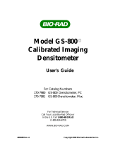
[6] READ HEAD - is the component that contains the optics which
comes in contact with your film when taking measurements.
[7] POWER SWITCH - turns the unit ON (1) and OFF (0).
[8] VOLTAGE SELECTION SWITCH - selects 115V or 230V
operation.
[9] FUSE HOLDER - holds the proper fuse.
[10] POWER INPUT - is where the 115V/230V AC line cord plugs in.
[11] REFLECTION HEAD INPUT - is used to connect optional
Reflection Head (see "Optional Equipment" in Chapter 8).
[12] I/O PORT - is used for RS232 bi-directional serial
communications.

OVERVIEW AND SETUP
1-3
Features
Electronic Filter Selection - eliminates the problems that mechanical
filter wheels create.
Large Liquid Crystal Display and Electroluminescent Backlighting -
allows optimum legibility.
Larger and Fewer Keys - which have been functionally placed for ease
of operation and to cut down operator confusion.
Sequence - allows for a setup of a measurement routine to meet the job
requirements. Once a sequence structure has been setup, the 361T will
automatically select the function for each step, then advance to the next
step, step by step. (A maximum of 36 steps) x10 provides an extra digit
of display when extreme resolution is required.
RS232 Interface & RCI - (Remote Control Interface) provides a two-
way interface for use with computerized quality control systems and
electronic printers.
Lamp Timer - if enabled, automatically turns OFF Reading lamp after 2
hours of instrument non-use. This will extend the life expectancy of the
read lamp.
Ortho and UV - responses allow measurements on a broad range of
films.
Density - provides density and density difference measurements.
+Dot - allows positive dot measurements with zeroing to a Base Dot.
+Dot can be calculated for a Base equal to 0% Dot or can be adjusted to
a value equal to a known Dot size (ex. 3%).
−Dot allows negative dot measurements with zeroing to a Base Dot.
−Dot can be calculated for a Base equal to 100% Dot or can be adjusted
to a value equal to a known Dot size (ex. 97%).
Unpack and Inspect
After removing the instrument from the shipping carton, inspect it for
damage. If any damage has occurred during shipping, immediately
contact the transportation company. Do not proceed with installation
until the carrier’s agent has inspected the damage.
Your instrument was packaged in a specially designed carton to assure
against damage. If shipment is necessary, the instrument should be
packaged in the original carton. If the original carton is not available,
contact X-Rite to have a replacement carton shipped to you.

CHAPTER ONE
1-4
Apply Power and Display Angle Adjustment
NOTE: If the unit has been stored in an abnormal (cold)
environment, DO NOT apply power to the unit until it has sat for
several hours in a normal environment (10-30°C / 50-86°F).
CAUTION: For safety and unit stability, do not modify line cord
provided with this instrument. Connect to a grounded 3-wire
receptacle.
1. Ensure that the proper operating line voltage is selected
(slide switch to 115 V or 230 V as necessary). Plug the
female end of the Power Cord into the back of the 361T,
and the other end into the wall outlet.
NOTE: When voltage setting is changed, the proper fuse, fuse
carrier, and line cord must be used. 115 VAC [Fuse SE24-0060,
Fuse Carrier SE71-05, Cord SD33-07] or 230 VAC [Fuse SE49-
0030, Fuse Carrier SE71-06, Cord SD33-08]
2. Set the Display Angle Adjustment to a midway setting.
3. Set the power switch to "1" (ON). Adjust the Display
Angle until the data in the display can best be seen at your
line of sight.
4. Upon power up, the unit will display the software date
code. Next, the unit will perform a self-test, and if
everything is ok, "TST Pass" will be displayed.
NOTE: If the unit does not pass the self-test, an error message
will be displayed, indicating the probable cause (Refer to
"Display Messages" in Chapter 2).
5. After the unit passes the self-test, the unit will
automatically return to the last function performed (ex.
DEN, +DOT, -DOT).
Display (EL) Backlighting
This feature backlights the display for use in reduced room lighting.
The Electroluminescent (EL) Backlighting turns OFF after 10 minutes
of instrument non-use, and turns back ON when a measurement is taken
or any key is depressed.

361T
DENSITOMETER
2-1
2. User Interface
Key Description
The Keyboard consists of three key switches, the [FUNCTION] d key,
the [
COLOR] c key, and the [ZERO] dc key.
FUNCTION
• Selects Density, +Dot, and −Dot.
NOTE: Sequence function is disabled from the factory, and will
not be displayed during function selection. If you want
Sequence enabled refer to "Setting the Sequence Structure" in
Chapter 5.
• Decreases numeric values when used with [ZERO] key.
• Depressed together with [
COLOR] to enter Calibration or
Modes.
COLOR
• Selects either Ortho or UV Filters during normal operation.
• Increases numeric values when used with [
ZERO] key.
• Depressed together with [
FUNCTION] to enter Calibration or
Modes.
ZERO
• Zeros density or Dot during a measurement.
• Used in conjunction with [
FUNCTION] or [COLOR] to
numerically enter a value.
NOTE: If you get lost while selecting functions or don't know
exactly where you are during a certain procedure. PRESS THE
[FUNCTION] KEY as many times as it takes until you get back
to a main level function (Den, +Dot, or −Dot).

CHAPTER TWO
2-2
DISPLAY CONTRAST
• Rotate the wheel to the back (+) to increase contrast or to the
front (-) to decrease contrast.
Function Selection
The [FUNCTION] key normally selects between one of three functions;
DEN, +DOT, or -DOT. They are sequentially selected with each
momentary depression of the [
FUNCTION] key. Once the function you
want is displayed, wait for the 361T to automatically drop into the
function selected (approximately a 2 second waiting period). At this
point, the previous measurement is displayed.
DEN
+DOT
-DOT
c #.##D
color
value
Density
wait 2 sec.
c ## %
+Dot
wait 2 sec.
c ##
-Dot
wait 2 sec.
Function
Displayed
If the Sequence Function is activated (see "Setting the Sequence
Structure" in Chapter 5), SEQUENCE will be displayed between -DOT
and DEN.

USER INTERFACE
2-3
NOTE: If DEN is the only function that can be activated, refer to
"311 Emulation" to turn it Off.
Color Selection
The [COLOR] Key selects one of two colors, Ortho or UV. They are
alternately selected with each depression of the [
COLOR] key. "o" is
displayed for Ortho and "u" for Ultraviolet.
Each depression of the [
COLOR] key will
alternately display "o" (Ortho) or "u"
(Ultraviolet).
o
u
o

CHAPTER TWO
2-4
Reference and Base Entry
Reference values are values, which are subtracted from each density
measurement to display a density difference value. Base values are
values, which cause +Dot or −Dot to display a predetermined Dot size
when zeroed to a base dot or film base fog.
Density Reference Entry Via Keyboard
1. Depress [
FUNCTION] key repeatedly [FUNCTION] until "DEN" is
displayed.
2. Select color by depressing the [
COLOR] key.
3. Hold [
ZERO] down (thru step 4).
• "REF" is displayed.
• Reference value is displayed.
4. Enter Ref value using the [
FUNCTION] key to decrease value or
[COLOR] key to increase value. (Depress both to reset to zero.)
Release keys.
5. Depress [
FUNCTION] to return to normal operation.
Density Reference Entry Via Measurement
Momentarily depress [
ZERO] while measuring area to be Zeroed
(Nulled) out.
1. Repeatedly depress [
FUNCTION] until "DEN" is displayed.
2. Select color by depressing [
COLOR].
3. Measure the density to be zeroed, and keep the [
READ] button
depressed (thru Step 4).
• "Density value of density being measured" is
displayed.
4. Press [
ZERO] key.
• "Zero density" is displayed.
5. Release the [
READ] button and [ZERO] key.

USER INTERFACE
2-5
Base Entry
The Base value is usually set to 0% for +DOT and 100% for -DOT, or
adjusted to a value equal to a known minimum (base) dot size (ex. 3%
for +Dot or 97% for −Dot).
1. Repeatedly depress [
FUNCTION] key until "+Dot" or "−Dot" is
displayed.
2. Select color by depressing [
COLOR].
3. Hold [
ZERO] key down (thru step 4).
• Base value is displayed.
4. Enter Base value using the [
FUNCTION] key to decrease or the
[
COLOR] key to increase value. (depress both to reset to zero.)
Release keys.
5. Depress [
FUNCTION] to return to normal operation.
Measurement Procedure - General
1. Select desired function and color.
2. Center area being measured over center of aperture.
3. Lower reading head by pressing on Read button. "READING" will
be displayed during a measurement cycle.
4. Release Read Button after data is displayed.
NOTE: "INVALID" will be displayed if the Read button is not
depressed for enough time.
Display Messages
MESSAGE REASON
BATTERY: The memory backup battery has failed. The Lithium
battery needs replacement by a qualified technician.
INVALID: The Read button was held down too short causing an
invalid measurement. If “INVALID” appears after the
Read button was held down for the proper length of
time or if “READING” is displayed an abnormal
length of time while taking a measurement, possible
causes are defective Side Sensor, Reading Head
Assembly, or Transmission PCB.
LAMP FAIL: The Read Lamp has failed its intensity test. The Read
Lamp should be examined and possibly replaced.
When this happens, you can get out of this error.

CHAPTER TWO
2-6
MESSAGE REASON
condition (if lamp was OK or replaced) by pressing
[FUNCTION], then [COLOR], then [FUNCTION].
MEM TEST: The memory in the unit is going through an extended
memory check. If “MEM TEST” remains on the
display, the display PCB needs to be replaced.
MEM LOST: Calibration of the unit has been lost and recalibration
is necessary.
NEED CAL: Unit needs full length calibration.
uP FAIL: The microprocessor has failed its memory test. The
display PCB should be replaced by a qualified
technician.
311 Emulation
When 311 EMULATION is set to ON, the 361T will simulate the I/O
port and some operational characteristics of the X-Rite 311/RS
densitometer. The modes are setup as follows: x10 OFF, I/O Port [RCI
ON, RPT OFF, P5 OFF, BAUD 1200, HDR OFF, DPT OFF, CR,
COMP OFF, and X OFF], SEQUENCE OFF, and READ LAMP ON.
The operational characteristics are setup as follows: DENSITY
operation is the only function that is accessible, and MODES are
disabled.
NOTE: To access 311 emulation, the AC power must be
turned off and then turned back on with the function and
color keys held depressed thru the self test until "311 off"
is displayed.
Described below is the procedure for setting the 311 Emulation.
1. Turn OFF power to the 361T.
2. Depress [
FUNCTION] and [COLOR] keys together (than turn on
A.C Power) until "311 OFF" is displayed.
3. Each depression of the [
ZERO] key will alternate between 311 ON
and 311 OFF.
4. Depress [
FUNCTION] one time to return to normal operation.

361T
DENSITOMETER
3-1
3. Measurement Procedures
Density Function
The DEN function allows you to take density and density difference
measurements. The procedure for each of these are as follow.
DENSITY MEASUREMENT
1. Repeatedly depress [
FUNCTION] key until "DEN" is displayed.
Previous density is displayed.
2. Select color (ortho or ultraviolet).
3. Measure film. Density value is displayed.
DENSITY DIFFERENCE MEASUREMENT
1. Repeatedly depress [
FUNCTION] key until "DEN" is displayed.
Previous density is displayed.
2. Select color (ortho or ultraviolet).
3. Enter a reference value. Refer to "Reference and Base Entry" in
Chapter 2 for entry of reference via the keyboard, or via a
measurement.
4. Measure film that is to be compared. Density difference value is
displayed.
+DOT Function
The +DOT function allows positive dot measurements with zeroing to a
Base Dot value. +Dot can be calculated for a Base equal to 0% Dot or
can be adjusted to a value equal to a known Dot size (ex. 3%). +DOT is
normally used for positive films.
+DOT MEASUREMENT
1. Repeatedly depress [
FUNCTION] until "+DOT" is displayed.
Previous Dot value is displayed.
2. Select color (ortho or ultraviolet).
3. Zero unit to a Base Dot or Base Fog of film, by pressing [
ZERO]
while measuring this area of the film.
4. Measure the Dot area on the film. +Dot value is displayed.

CHAPTER THREE
3-2
-DOT Function
−Dot allows negative dot measurements with zeroing to the Base Dot
value. −Dot can be calculated for a Base equal to 100% or can be
adjusted to a value equal to a known Dot size (ex. 97%). -DOT is
normally used for negative films.
-DOT MEASUREMENT
1. Repeatedly depress the [
FUNCTION] key until "-DOT" is displayed.
Previous Dot value is displayed.
2. Select color (ortho or ultraviolet).
3. Zero unit to a Base Dot or Base Fog of film, by pressing [
ZERO]
while measuring this area of the film.
4. Measure the film. −Dot value is displayed. Repeatedly depress
[
FUNCTION] until "+DOT" is displayed. Previous Dot value is
displayed.
Sequence (Disabled from factory)
The Sequence function allows a setup of a measurement sequence to
meet the job requirements. Once a sequence structure has been setup
(see "Setting the Sequence Structure" in Chapter 5 for setup procedure)
the 361T will automatically select the function and advance to the next
step, step by step. Once in the Sequence function, a depression of the
Read button advances to the next step. However, the 361T can
increment or decrement thru the steps by depressing and holding dc
[
ZERO] key and then depressing d [FUNCTION] key to decrement or
c [COLOR] key to increment.
IMPORTANT! The Density/Dot value for each sequence step is
displayed during the measurement (Read button depressed).
When the Read button is released, the display shows the next
step to measure. If you desire to view the Density/Dot value for
the last step measured, press the [ZERO] key to view it, and
then press [ZERO] again to return.
NOTE: During sequence operation, look at the display and
make sure each measurement is correct before releasing the
Read button to proceed to the next step.
The example Sequence procedure below shows a sequence that was
setup using two steps, and it starts out at step1. When entering sequence,
the function will always start at the lowest step enabled.

MEASUREMENT PROCEDURES
3-3
1. Repeatedly depress the [
FUNCTION] key until "SEQUENCE" is
displayed. (If sequence does not appear, refer to "Setting the
Sequence Structure" in Chapter 5). Function, Color, and Step to be
measured first is displayed.
2. Select color (ortho or ultraviolet).
3. Take first measurement.
4. Measurement value and Step number are displayed while the
[
READ] button is held down. After Read button is released, Step 2
is displayed.
5. Take second measurement.
6. Measurement value and step number are displayed while the read
button is held down.
* After release of the Read button, the display will ask if you want
to print out. If yes, press [
COLOR]. If no, press [ZERO] or
[FUNCTION].
NOTE:
1) "PRINT? C" will only be displayed if the Sequence printout
procedure in Mode Setup is selected for CLASS or ORDER. It
will automatically print out after each measurement (step) if
EACH was selected. (See "Setting the Sequence Structure" in
Chapter 5.)
2) When Step 00 is setup for "ZERO 00" the unit will use the
same Zero (reference) value for Den, +Dot, or −Dot.
3) The Zero (reference) value is common to all Density steps, all
+Dot steps, and/or all −Dot steps, for step zero (00) only. On
any other step, if the unit is zeroed, the zeroing only applies for
the function that was selected for that step.

CHAPTER THREE
3-4
/