Page is loading ...

CAUTION
Read all precautions and instruc
-
tions in this manual before using
this equipment. Save this manual
for future reference.
Model No. VMSY80407.0
Serial No.
Write the serial number in the
space above for future reference.
QUESTIONS?
At FreeMotion Fitness, we are
committed to providing com-
plete customer satisfaction. If
you have questions, see HOW
TO CONTACT CUSTOMER
CARE on the back cover of this
manual.
Visit our website at
www.weslo.com
new products, prizes,
fitness tips, and much more!
V
Visit our website at
www.proform.com
new products, prizes,
fitness tips, and much more!
Visit our website at
www.healthrider.com
new products, prizes,
fitness tips, and much more!
V
Visit our website at
www.freemotionfitness.com
V
Serial Number Decal
USER’S
MANUAL

WARNING: To reduce the risk of serious injury, read all important precautions and
i
nstructions in this manual before attaching weight stations to the center column. FreeMotion
Fitness assumes no responsibility for personal injury or property damage sustained by or through
the use of the center column.
IMPORTANT PRECAUTIONS
1. Before beginning any exercise program, con-
sult your physician. This is especially impor-
tant for persons over the age of 35 or per-
sons with pre-existing health problems.
2. Use the center column only as described in
this manual.
3. Keep the center column indoors, away from
moisture and dust. Place the center column
on a level surface, with a mat beneath it to
protect the floor or carpet.
4. To prevent the center column from tipping
over, lay it on the floor until you are ready to
attach one of the weight stations.
2
Thank you for purchasing the center column for the versatile
FREEMOTION
®
CARBON™ weight system. The center column con-
nects a series of weight stations designed to develop every major
muscle group of the body: the TRAVELING PULLEY station (model
no. VMSY80507.0), the LEG DEVELOPER station (model no.
VMSY80607.0), the PRESS station (model no. VMSY80707.0), the
WEIGHT ASSIST station (model no. VMSY80807.0), and the LEG
PRESS station (model no. VMSY80907.0).
To purchase additional
stations, please call the telephone number on the back cover of
this manual.
Whether your goal is to tone your body, build dramatic muscle size
and strength, or improve your cardiovascular system, the
FREEMOTION CARBON weight system will help you to achieve the
specific results that you want.
For your benefit, read this manual carefully before you attach
weight stations to the center column.
If you have questions after
reading this manual, or if you need to order replacement leveling
feet, see HOW
T
O CONT
ACT
CUST
OMER CARE on the back cover
of this manual.
Before attaching weight stations, make sure that the five level
-
ing feet are attached to the center column.
BEFORE YOU BEGIN
Leveling
Feet
Height: 82 in.
(208 cm)
Weight: 71 lbs.
(32 kg)

3
FreeMotion Fitness warrants this product to be free
from defects in workmanship and material under nor-
mal use and service conditions. The warranty period
commences on the invoice date of purchase. Any
parts repaired or replaced during this warranty period
will be warranted for the remainder of the original war-
ranty period.
WARRANTY PERIODS AND COVERAGE
Residential and Light Commercial
Frame: Lifetime
Parts: 10 years
Cables/Belts: 1 year
Upholstery and Accessories: 90 days
Labor: 1 year
Light commercial use is defined as a non-dues-paying
institutional setting to include hotels, apartment fitness
centers, corporate fitness centers, fire/police stations,
and hospital/physical therapy settings. This product is
not intended to be used in large, heavy-use settings
such as health clubs, colleges/universities, community
centers, or military installations. Use of this product in
such facilities will void this warranty.
CONDITIONS AND LIMITATIONS
The following will void the warranty on this product:
1. This warranty applies only to the original owner and
is non-transferable.
2. The 1-year labor warranty applies only to products
sold in the US and Canada. Contact your authorized
FreeMotion Fitness dealer for details on labor cov-
erage in your country.
3. Any misuse, abuse, improper service.
4. Users in excess of 350 lbs. (159 kg) in weight.
5.
Damage caused by moving the product or improper
storage including moving or storing the product on
its side.
6.
Use or storage of the product outdoors or in high-
humidity environments including spas and pools.
This warranty shall not apply to the following:
1. Cosmetic items including grips, decals, and labels.
2. Pick-up and delivery of freight charges involved with
a repair.
3. Any problem as a result of improper assembly or
delivery.
WHAT TO DO IF SERVICE IS REQUIRED
FreeMotion Fitness warranty service may be obtained
by contacting the authorized dealer from which you
purchased your equipment. Make sure to retain your
original invoice and serial number information. If this
product experiences a failure under the warranty terms
set forth, FreeMotion Fitness shall provide at their
option either repair, replacement, or refund of the pur-
chase price. FreeMotion Fitness compensates service
providers for warranty trips within their service area.
You may be charged additionally for service calls
beyond this service area.
FreeMotion Fitness is not responsible or liable for indi-
rect, special or consequential damages arising out of
or in connection with the use or performance of the
product or damages with respect to any economic
loss, loss of property, loss of revenues or profits, loss
of enjoyment or use, cost of removal, installation or
other consequential damages. Some states do not
allow the exclusion or limitation of consequential dam-
ages. Accordingly, the above limitation may not apply
to you. This warranty gives you specific rights and you
may have other rights that vary from state to state.
TO CONTACT FREEMOTION FITNESS
See HOW TO CONTACT CUSTOMER CARE on the
back cover of this manual.
LIMITED WARRANTY

Part No. 252590 R0807A Printed in China © 2007 ICON IP, Inc.
HOW TO CONTACT CUSTOMER CARE
If you have questions after reading this manual, if you require assistance, or if you need to order replacement
parts, please contact Customer Care at the address or phone number listed below. Please be prepared to pro-
vide the following information:
• the model number and serial number of the product (see the front cover of this manual)
• the name of the product (see the front cover of this manual)
When ordering replacement parts, please also provide the KEY NUMBER and DESCRIPTION of the part(s) (see
the PART LIST and the EXPLODED DRAWING near the end of this manual).
Call
Toll-free in the US: 1-866-799-8946, Mon.–Fri. 8 a.m.–5 p.m. MST
International: +1-719-533-2911
Email
International: [email protected]
Write
FreeMotion Fitness
1096 Elkton Drive Suite 600
Colorado Springs CO 80907

CAUTION
Read all precautions and instruc
-
tions in this manual before using
this equipment. Save this manual
for future reference.
Model No. VMSY80507.0
Serial No.
W
rite the serial number in the
space above for future reference.
QUESTIONS?
At FreeMotion Fitness, we are
committed to providing com-
plete customer satisfaction. If
you have questions, see HOW
TO CONTACT CUSTOMER
CARE on the back cover of this
manual.
Visit our website at
www.weslo.com
new products, prizes,
fitness tips, and much more!
V
Visit our website at
www.proform.com
new products, prizes,
fitness tips, and much more!
Visit our website at
www.healthrider.com
new products, prizes,
fitness tips, and much more!
V
Visit our website at
www.freemotionfitness.com
V
Serial Number Decal
(behind foot plate)
USER’S
MANUAL

2
WARNING DECAL PLACEMENT
W
ARNING DECAL PLACEMENT . . . . . . . . . . . . . . . . . . . . . . . . . . . . . . . . . . . . . . . . . . . . . . . . . . . . . . . . . . . . . 2
IMPORTANT PRECAUTIONS . . . . . . . . . . . . . . . . . . . . . . . . . . . . . . . . . . . . . . . . . . . . . . . . . . . . . . . . . . . . . . . . 3
BEFORE YOU BEGIN . . . . . . . . . . . . . . . . . . . . . . . . . . . . . . . . . . . . . . . . . . . . . . . . . . . . . . . . . . . . . . . . . . . . . . 4
PART IDENTIFICATION CHART . . . . . . . . . . . . . . . . . . . . . . . . . . . . . . . . . . . . . . . . . . . . . . . . . . . . . . . . . . . . . .5
A
SSEMBLY . . . . . . . . . . . . . . . . . . . . . . . . . . . . . . . . . . . . . . . . . . . . . . . . . . . . . . . . . . . . . . . . . . . . . . . . . . . . . . 6
ADJUSTMENT . . . . . . . . . . . . . . . . . . . . . . . . . . . . . . . . . . . . . . . . . . . . . . . . . . . . . . . . . . . . . . . . . . . . . . . . . . . 16
MAINTENANCE . . . . . . . . . . . . . . . . . . . . . . . . . . . . . . . . . . . . . . . . . . . . . . . . . . . . . . . . . . . . . . . . . . . . . . . . . .17
CABLE DIAGRAM . . . . . . . . . . . . . . . . . . . . . . . . . . . . . . . . . . . . . . . . . . . . . . . . . . . . . . . . . . . . . . . . . . . . . . . . .18
EXERCISE GUIDELINES . . . . . . . . . . . . . . . . . . . . . . . . . . . . . . . . . . . . . . . . . . . . . . . . . . . . . . . . . . . . . . . . . . .19
LIMITED WARRANTY . . . . . . . . . . . . . . . . . . . . . . . . . . . . . . . . . . . . . . . . . . . . . . . . . . . . . . . . . . . . . . . . . . . . . 21
PART LIST . . . . . . . . . . . . . . . . . . . . . . . . . . . . . . . . . . . . . . . . . . . . . . . . . . . . . . . . . . . . . . . . . . . . . . . . . . . . . .22
EXPLODED DRAWING . . . . . . . . . . . . . . . . . . . . . . . . . . . . . . . . . . . . . . . . . . . . . . . . . . . . . . . . . . . . . . . . . . . .23
HOW TO CONTACT CUSTOMER CARE . . . . . . . . . . . . . . . . . . . . . . . . . . . . . . . . . . . . . . . . . . . . . . .Back Cover
TABLE OF CONTENTS
The decal shown here has been placed in the
indicated location. If the decal is missing or
illegible, call the telephone number on the back
cover of this manual and request a free replace-
ment decal. Apply the decal in the location
shown. Note: The decal may not be shown at
actual size.
FREEMOTION is a registered trademark of ICON IP, Inc.
259345

3
WARNING: To reduce the risk of serious injury, read all important precautions and
i
nstructions in this manual and all warnings on the weight station before using the weight station.
FreeMotion Fitness assumes no responsibility for personal injury or property damage sustained by
or through the use of the weight station.
IMPORTANT PRECAUTIONS
1. Before beginning any exercise program, con-
sult your physician. This is especially impor-
tant for persons over the age of 35 or per-
sons with pre-existing health problems.
2. Use the weight station only as described in
this manual.
3. It is the responsibility of the owner to ensure
that all users of the weight station are ade-
quately informed of all precautions.
4. Keep the weight station indoors, away from
moisture and dust. Place the weight station
on a level surface, with a mat beneath it to
protect the floor or carpet. Make sure that
there is enough clearance around the weight
station to mount, dismount, and use it.
5. Keep hands and feet away from moving
parts.
6. Keep children under age 12 and pets away
from the weight station at all times.
7. Inspect and properly tighten all parts regular-
ly. Replace any worn parts immediately.
8. Make sure that the cables remain on the pul-
leys at all times. If a cable binds while you
are exercising, stop immediately and make
sure that the cable is on the pulleys.
9. Wear appropriate clothes while exercising.
Always wear athletic shoes for foot protec-
tion while exercising.
10. Always make sure that the weight pin is fully
inserted into the weight stack before you
exercise.
11. To prevent the weight system from tipping
over, always assemble another station (sold
separately) to the center column (sold sepa-
rately) before assembling the TRAVELING
PULLEY station.
12. If you feel pain or dizziness while exercising,
stop immediately and cool down.

4
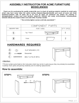
Weights
Foot Plate
Adjustment Knob
Weight Pin
Handle
Ankle Strap
Shroud
Lat Bar
Note: The FREEMOTION CARBON weight system can include the following weight stations (sold
separately): the TRAVELING
PULLEY
station (model no. VMSY80507.0), the
LEG DEVELOPER
station (model no. VMSY80607.0), the PRESS station (model no. VMSY80707.0), the WEIGHT
ASSIST station (model no. VMSY80807.0), and the LEG PRESS station (model no. VMSY80907.0).
T
o purchase additional stations, please call the telephone number on the back cover of this
manual.
Pulley Carriage
Upright
BEFORE YOU BEGIN
Thank you for selecting the TRAVELING PULLEY sta-
tion for the versatile FREEMOTION
®
CARBON™
weight system. The TRAVELING PULLEY station is
one of a series of weight stations designed to develop
every major muscle group of the body. Whether your
g
oal is to tone your body, build dramatic muscle size
and strength, or improve your cardiovascular system,
the weight system will help you to achieve the specific
results that you want.
For your benefit, read this manual carefully before
you use the weight station. If you have questions
after reading this manual, see HOW TO CONTACT
CUSTOMER CARE on the back cover of this manual.
To help us assist you, note the product number and
serial number before contacting us. The model number
and the location of the serial number decal are shown
o
n the front cover of this manual.
Before reading further, please review the drawing
below and familiarize yourself with the parts that are
labeled.
Assembled Dimensions:
Height: 82 in. (208 cm)
Width: 42 in. (107 cm)
Depth: 36 in. (91 cm)
Weight: 136 lbs. (62 kg)

M10 Washer (37)
M6.5 Washer (54)
P
M10 x 19mm
Screw (52)
M10 x 45mm Bolt (56)
M10 x 54mm Bolt (41)
M10 x 66mm Bolt (34)
M10 x 19mm
Hex Screw (40)
M5 x 25mm
Screw (47)
M10 Thick Nylon
Locknut (38)
M6 Nylon
Locknut (53)
M8 x 8mm
Set Screw (45)
S
ee the drawings below to identify small parts used in assembly. The number in parentheses by each drawing is
the key number of the part, from the PART LIST near the end of this manual. Note: Some small parts may
h
ave been preattached. If a part is not in the hardware kit, check to see if it has been preattached.
PART IDENTIFICATION CHART
5

6
ASSEMBLY
1.
Attach the Base (10) to the center column with
four M10 x 19mm Hex Screws (40).
Before beginning assembly, make sure
that you understand the information in the
box above. Note: Some parts described in
the assembly steps may be preassembled.
IMPORTANT: To prevent the weight system
from tipping over, always assemble anoth-
er station (sold separately) to the center
column (sold separately) before assem-
bling the TRA
VELING PULLEY station.
1
Before beginning assembly, carefully read the
following information and instructions:
• Assembly requires two persons.
• Because of its weight and size, the weight station
should be assembled in the location where it will
be used. Make sure that there is enough clear-
ance to walk around the weight station as you
assemble it.
If attaching additional stations to
the column, leave enough clearance for those
stations.
• Place all parts in a cleared area and remove the
packing materials. Do not dispose of the packing
materials until assembly is completed.
• For help identifying small parts, use the PART
IDENTIFICATION CHART on page 5.
• As you assemble the weight station, make sure
a
ll parts are oriented as shown in the drawings.
• Tighten all parts as you assemble them, unless
instructed to do otherwise.
• Assembly requires the included hex key and
grease and may require the following tools:
Two adjustable wrenches
One rubber mallet
One standard screwdriver
One Phillips screwdriver
One torque wrench (not shown)
Assembly will be more convenient if you have a
socket set, a set of open-end or closed-end
wrenches, or a set of ratchet wrenches.
Make Assembly Easier
E
verything in this manual is designed to ensure
that the weight station can be assembled suc-
cessfully by almost anyone. By setting aside
plenty of time, assembly will go smoothly.
10
40
40
Make sure that the five
leveling feet are
attached to the center
column (see the User’s
Manual included with
the center column).
Center
Column
Leveling
Feet

7
2. Attach the Foot Plate (13) to the Base (10) with
two M10 x 66mm Bolts (34) and two M10 Thick
N
ylon Locknuts (38).
2
3. Attach the Upright (12) to the Base (10) with two
M10 x 66mm Bolts (34)
and two M10 Thick Nylon
Locknuts (38). Do not tighten the Thick Nylon
Locknuts yet.
3
4. Attach the Top Frame (11) to the center column
with four M10 x 19mm Hex Screws (40). Do not
tighten the Screws yet.
Attach the Top Frame (11) to the Upright (12) with
two M10 x 54mm Bolts (41) and two M10 Thick
Nylon Locknuts (38). Do not tighten the Thick
Nylon Locknuts yet.
4
11
40
41
40
38
12
10
10
13
12
38
34
34
38
Center
Column

8
5. See the CABLE DIAGRAM on page 18 to iden-
tify the cables as you assemble them.
Identify the Short Cable (36).
Feed the threaded
e
nd of the Cable through the Small Pulley
Bracket (18), above the Small Pulley (14) that is
inside the Small Pulley Bracket. Continue feeding
the Cable into the Top Frame (11);
look up into
the indicated openings and make sure that the
Cable is above the two welded pins inside the
Top Frame. Then, pull the end of the Cable out
of the indicated slot in the Top Frame.
5
11
W
elded
Pins
S
lot
18
36
14
6. Route the Short Cable (36) downward through
the Top Frame (11) as shown. Insert a Small
Pulley (14) into the slot in the Top Frame. Attach
the Small Pulley with an M10 x 66mm Bolt (34),
two M10 Washers (37), two Pulley Spacers (29),
and an M10 Thick Nylon Locknut (38).
6
11
34
36
37
29
38
14
37
29
7.
Route the Short Cable (36) under a Small Pulley
(14) that is attached between the Pulley Plates
(16). Make sure that the Cable is between the
Small Pulley and the Cable T
rap (15).
7
14
16
15
36
Openings

9
8. Route the Short Cable (36) through the bumper
bracket as shown. Next, wrap the Cable over a
S
mall Pulley (14). Attach the Small Pulley inside
the Top Frame (11) with an M10 x 66mm Bolt
(
34), two M10 Washers (37), two Pulley Spacers
(29), and an M10 Thick Nylon Locknut (38).
8
1
1
38
2
9
37
29
37
34
36
14
9. Identify the Long Cable (39). Feed the threaded
end of the Cable through the Large Pulley
Bracket (17). Wrap the Cable over the Large
Pulley (49) that is inside the Large Pulley Bracket.
Route the Long Cable (39) through the Base (10)
as shown. Attach a Small Pulley (14) inside the
indicated slot in the Base with an M10 x 66mm
Bolt (34), two M10 Washers (37), two Pulley
Spacers (29), and an M10 Thick Nylon Locknut
(38).
9
39
49
38
37
29
10
34
29
37
17
Slot
14

10
11
29
37
10
38
29
14
37
39
34
11. Route the Long Cable (39) through the Base (10)
as shown. Attach a Small Pulley (14) inside the
Base with an M10 x 66mm Bolt (34), two M10
Washers (37), two Pulley Spacers (29), and an
M10 Thick Nylon Locknut (38).
10
10. Route the Long Cable (39) over the Small Pulley
(
14) that is attached to bottom of the Pulley
Plates (16).
Make sure that the Cable is
between the Pulley and the Cable Trap (15).
15
16
39
14

11
13
14
13. Attach a Large Pulley (49) inside the indicated
slot in the Base (10) with an M10 x 45mm Bolt
(56) and an M10 Thick Nylon Locknut (38).
14. W
rap the Long Cable (39) over a Small Pulley
(14). Attach the Small Pulley inside the Top
Frame (11) with an M10 x 66mm Bolt (34), two
M10 Washers (37), two Pulley Spacers (29), and
an M10 Thick Nylon Locknut (38).
38
10
56
Slot
49
11
29
37
38
37
39
34
14
12
12. Attach a Small Pulley (14) inside the Base (10)
with an M10 x 66mm Bolt (34), two M10 Washers
(
37), two Pulley Spacers (29), and an M10 Thick
Nylon Locknut (38).
29
37
10
38
29
14
37
34
29

12
15
16
8
52
10
15. Feed the Long Cable (39) downward into the
back of the Pulley Carriage (23). Tighten an M6
N
ylon Locknut (53) onto the end of the Cable.
53
23
39
16. Attach the two Weight Guides (8) to the Base (10)
with two M10 x 19mm Screws (52).
Do not tight-
en the Screws yet.
17
10
1
47
17. Attach the Shroud Base (1) to the Base (10) with
two M5 x 25mm Screws (47) and two M6.5
Washers (54).
54
54
47

13
18
8
31
Center
Hole
18. Orient the Weight Bumper (31) as shown, and
then slide it onto the Weight Guides (8).
Orient the nineteen Weights (6) so that the pin
h
oles are positioned as shown. Slide the Weights
onto the Weight Guides (8).
6
19
19. Orient the Top Weight (48) as shown. Slide the
Top Weight onto the Weight Guides (8). Insert the
Weight Pin (9) into the hole in a Weight (6) and a
hole in the Weight Tube (7).
48
6
8
7
9
20
36
28
45
20.
Slide the W
eight Tube Cover (28) over the Short
Cable (36). Then, insert the Cable into the Weight
T
ube (7) until all four M8 x 8mm Set Screws (45)
can be tightened against the Cable.
T
ighten each
Screw alternately 1/4 turn, until all are set to 85
inch/pounds (9.6 Newton-meters).
P
in
H
ole
45
7

14
21
52
8
11
21. Attach the Weight Guides (8) to the Top Frame
(11) with two M10 x 19mm Screws (52).
See steps 3 and 4. Tighten the M10 x 19mm
H
ex Screws (40) and the M10 Thick Nylon
Locknuts (38).
See step 16. Tighten the M10 x 19mm Screws
(52).
22
2
54
11
47
22. Attach the Shroud Top (2) to the Top Frame (11)
with two M5 x 25mm Screws (47) and two M6.5
Washers (54).

15
23
24
5
1
2
1
2
3
57
57
24. Lift the Left Shroud (4) up into the front of the
Shroud Top (2). Then, slide the Left Shroud
downward into the Shroud Base (1).
Next, slide the Right Shroud (5) into the Shroud
Base (1) in the same way.
Attach the Rear Shroud (3) to the Right Shroud
(5) and the Left Shroud (4) with the two Shroud
Joints (not shown).
23. Note: If attaching all the stations to the center
column, it is not necessary to attach the Rear
S
hroud (3) and the Shroud Joints (57).
F
or clarity, the weight stack is not shown in
steps 23 and 24.
Lift the Rear Shroud (3) up into the back of the
Shroud Top (2). Then, slide the Rear Shroud
downward into the Shroud Base (1).
Press the Shroud Joints (57) onto both sides of
the Rear Shroud (3). Have a second person hold
the Shroud Joints until step 24 is completed.
4
3
25. Make sure that all parts are properly tightened
before you use the weight station. The use of
the remaining parts will be explained in ADJUST-
MENT, beginning on page 16.

16
C
HANGING THE WEIGHT SETTING
To change the weight setting of the weight stack,
insert the Weight Pin (9) into the hole in the desired
Weight (6). Make sure that the Weight Pin goes
into the Weight Tube (not shown).
12
9
6
ADJUSTING THE PULLEY
CARRIAGE
T
o adjust the height of the Pulley Carriage (23), pull
the Adjustment Knob (27), slide the Pulley Carriage to
the desired height, and then engage the Adjustment
Knob into one of the adjustment holes in the Upright
(12). Make sure that the Adjustment Knob is fully
engaged in one of the holes in the Upright.
ADJUSTMENT
23
27
This section explains how to adjust the weight station. See the EXERCISE GUIDELINES on page 19 for impor-
tant information about how to get the most benefit from your exercise program. Also, refer to the accompanying
exercise guide to see the correct form for several exercises.
19
36
39
22
ATTACHING THE ACCESSORIES
To use the Short Cable (36), first select the desired
weight setting (see CHANGING THE WEIGHT SET-
TING above). Next, attach the Lat Bar (19) to the
Short Cable with a Cable Clip (22).
To use the Long Cable (39), attach the Lat Bar (19) to
the Long Cable in the same way.
See the inset drawing. The Pulley Handle (21) and
the
Ankle Strap (20) can be attached to the Cables
(36, 39) in the same way.
WARNING: Always disconnect the
Lat Bar (19) when performing an exercise that
does not require using the Lat Bar.
21
20
/