Page is loading ...

(2720)A 1
REPAIR GUIDE
REPAIR GUIDE
This repair guide section contains the disassembly and adjustment procedures.
For the assembly procedure, follow the reverse procedure.
SYMBOLS
:Cautions and keypoints
: Grease
: Adhesive
: Tool
CONTENTS Page CONTENTS Page
Precautions------------------------------------------------- 2
Discharge --------------------------------------------------- 3
1. Disassembly of the exterior parts ------------------ 4
2. Disassembly of the compl PWB TB-3, LCD------ 8
3. Disassembly of the assy cabi front,
compl PWB TB-3/CA-2/TC-1 ---------------------12
4. Disassembly of the compl PWB SY-1/
ST-1/PW-1/TB-1/SY-2/DM-1 ----------------------18
5. Disassembly of the CCD holder assy,
the outer barrel assy and the 1st lens group
moving barrel. ---------------------------------------22
6. Disassembly of the outer barrel assy -------------25
7. Disassembly of the 4th moving barrel assy,
the 3rd moving barrel assy and the 2nd lens
group assy. ---------------------------------------------27
Arrangement plan of PCB -----------------------------29
Required adjustment, setting and confirmation
items after repairing (exchanging parts) --------30
Related adjustment and required setting items --- 31
Preparing the 2782 adjustment program-----------32
Starting up the 2782 adjustment program
(in the adjustment mode). -------------------------- 33
Contents of the adjustment program and CPU
version readout ----------------------------------------34
Setting the camera and the chart when
adjusting the CCD perspective.--------------------35
Adjustment of CCD perspective-----------------------37
Sensitivity adjustment (GAIN) -----------------------39
Adjusting the center part of CCD
(CCD CENTER) ---------------------------------------40
Adjustment of the frequency for camera shaking
(ACT DRV FREQ) ------------------------------------41
Adjustment of the servo for camera shaking
(SERVO GAIN)----------------------------------------41
Adjustment of the gyro for camera shaking
(GYRO OFFSET) -------------------------------------42
Adjustment of the shutter (SHUTTER) -------------43
Adjustment of the defective pixel
(DEFECT PIXEL) ------------------------------------43
Adjustment of the flash GN (FL GNo) --------------44
Adjustment of white balance (WB) -------------------45
Adjustment of the focus (FCS INF POS) -----------46
Adjustment of the manual focus PI (MF PI) -------47
Adjustment of the camera shaking compensation
(SHAKE OFFSET) -----------------------------------48
DESTINATION Setting (DESTINATION) --------49
Setting date and time (TOD) --------------------------49
Error code on adjustment program ------------------50
Measuring instrument----------------------------------51
Subsidiary Materials ------------------------------------52

2 (2720)A
REPAIR GUIDE
Precautions
Chemicals
Handle chemicals of high volatility with care, use of which will affect to your health and environment.
1. Store them sealed in a specific place to prevent exposure to high temperature or direct sunlight.
2. Avoid dividing them into small containers and prevent vaporization.
3. Keep containers sealed when not in use.
4. Avoid using them as much as possible. When required, remove only required amount from the
container to make full use.
Plastic parts
1. When cleaning plastic parts, use cleaning paper or cloth. Never use thinner, ketone, ether.
2. When installing plastic parts, insert the specific screws vertically to the parts. (Be careful not to
tighten too much.
PCBs
Since PCBs use MOS IC, you must reduce static electricity. When repairing a PCB itself, or when
wiring, please perform your work as illustrated below.
If grounding is impossible, connect a cable to a steel desk or shelf.
Keep touching the conductiveKeep touching the conductive
Keep touching the conductiveKeep touching the conductive
Keep touching the conductive
mat while you work.mat while you work.
mat while you work.mat while you work.
mat while you work.
Conductive MatConductive Mat
Conductive MatConductive Mat
Conductive Mat
GNDGND
GNDGND
GND
1M1M
1M1M
1M

(2720)A 3
REPAIR GUIDE
Fig. 1Fig. 1
Fig. 1Fig. 1
Fig. 1
Discharge
Before disassembly, be sure to discharge the main condenser in the following manner. (Fig. 1)
Short-circuit with discharger or resistor of 200-300 ohm/3w.
Check voltage to make sure it is discharged.

4 (2720)A
REPAIR GUIDE
1
2
3
4
5
5
6
7
8
9
10
12
11
14
15
16
17
18
19
20
21
22
13
Fig. 3, 5Fig. 3, 5
Fig. 3, 5Fig. 3, 5
Fig. 3, 5
Fig. 2Fig. 2
Fig. 2Fig. 2
Fig. 2
Fig. 1, 4Fig. 1, 4
Fig. 1, 4Fig. 1, 4
Fig. 1, 4
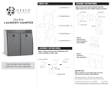
1. Disassembly of the exterior parts
Disassemble it in order of step 1to 22Disassemble it in order of step 1to 22
Disassemble it in order of step 1to 22Disassemble it in order of step 1to 22
Disassemble it in order of step 1to 22

(2720)A 5
REPAIR GUIDE
2782-12962782-1296
2782-12962782-1296
2782-1296
2782-12982782-1298
2782-12982782-1298
2782-1298
04930493
04930493
0493
Fig. 1 Installation of the cabinet sideFig. 1 Installation of the cabinet side
Fig. 1 Installation of the cabinet sideFig. 1 Installation of the cabinet side
Fig. 1 Installation of the cabinet side
1. Arrange the FPC of the cabinet side as shown on the figure.1. Arrange the FPC of the cabinet side as shown on the figure.
1. Arrange the FPC of the cabinet side as shown on the figure.1. Arrange the FPC of the cabinet side as shown on the figure.
1. Arrange the FPC of the cabinet side as shown on the figure.
2. Stick 2782-1296 as shown on the figure to prevent the FPC of the cabinet side from unstableness.2. Stick 2782-1296 as shown on the figure to prevent the FPC of the cabinet side from unstableness.
2. Stick 2782-1296 as shown on the figure to prevent the FPC of the cabinet side from unstableness.2. Stick 2782-1296 as shown on the figure to prevent the FPC of the cabinet side from unstableness.
2. Stick 2782-1296 as shown on the figure to prevent the FPC of the cabinet side from unstableness.
FPC of the cabinet sideFPC of the cabinet side
FPC of the cabinet sideFPC of the cabinet side
FPC of the cabinet side
Fig. 2 Installation of the assy, cabi backFig. 2 Installation of the assy, cabi back
Fig. 2 Installation of the assy, cabi backFig. 2 Installation of the assy, cabi back
Fig. 2 Installation of the assy, cabi back
Install the assy cabi back with a care of the FPC ofInstall the assy cabi back with a care of the FPC of
Install the assy cabi back with a care of the FPC ofInstall the assy cabi back with a care of the FPC of
Install the assy cabi back with a care of the FPC of
the cabinet side.the cabinet side.
the cabinet side.the cabinet side.
the cabinet side.
FPC of the cabinet sideFPC of the cabinet side
FPC of the cabinet sideFPC of the cabinet side
FPC of the cabinet side
Compl PWB SY-1Compl PWB SY-1
Compl PWB SY-1Compl PWB SY-1
Compl PWB SY-1
Fig.3 Installation of the Cabinet topFig.3 Installation of the Cabinet top
Fig.3 Installation of the Cabinet topFig.3 Installation of the Cabinet top
Fig.3 Installation of the Cabinet top
1. Stick 0493 and 2782-1163 at the points on the figure. 1. Stick 0493 and 2782-1163 at the points on the figure.
1. Stick 0493 and 2782-1163 at the points on the figure. 1. Stick 0493 and 2782-1163 at the points on the figure.
1. Stick 0493 and 2782-1163 at the points on the figure.
Compl PWB SY-1Compl PWB SY-1
Compl PWB SY-1Compl PWB SY-1
Compl PWB SY-1

6 (2720)A
REPAIR GUIDE
B B-10B B-10
B B-10B B-10
B B-10
2782-11632782-1163
2782-11632782-1163
2782-1163
2. Stick 2782- 1163 at the points on the figure. 2. Stick 2782- 1163 at the points on the figure.
2. Stick 2782- 1163 at the points on the figure. 2. Stick 2782- 1163 at the points on the figure.
2. Stick 2782- 1163 at the points on the figure.
3. Arrange the harness as shown on the figure to install the cabinet top. 3. Arrange the harness as shown on the figure to install the cabinet top.
3. Arrange the harness as shown on the figure to install the cabinet top. 3. Arrange the harness as shown on the figure to install the cabinet top.
3. Arrange the harness as shown on the figure to install the cabinet top.
Fig.4 Assembly of the cabinet sideFig.4 Assembly of the cabinet side
Fig.4 Assembly of the cabinet sideFig.4 Assembly of the cabinet side
Fig.4 Assembly of the cabinet side
1. Solder the lead wire and harness and arrange them as shown on the figure.1. Solder the lead wire and harness and arrange them as shown on the figure.
1. Solder the lead wire and harness and arrange them as shown on the figure.1. Solder the lead wire and harness and arrange them as shown on the figure.
1. Solder the lead wire and harness and arrange them as shown on the figure.
2. Apply B-10 as shown on the figure.2. Apply B-10 as shown on the figure.
2. Apply B-10 as shown on the figure.2. Apply B-10 as shown on the figure.
2. Apply B-10 as shown on the figure.
3. Press the FPC of the control side unit in the arrowed direction to prevent it from unstableness.3. Press the FPC of the control side unit in the arrowed direction to prevent it from unstableness.
3. Press the FPC of the control side unit in the arrowed direction to prevent it from unstableness.3. Press the FPC of the control side unit in the arrowed direction to prevent it from unstableness.
3. Press the FPC of the control side unit in the arrowed direction to prevent it from unstableness.
Lead wireLead wire
Lead wireLead wire
Lead wire
HarnessHarness
HarnessHarness
Harness
Lead wire (Gray):Lead wire (Gray):
Lead wire (Gray):Lead wire (Gray):
Lead wire (Gray):
Solder them withSolder them with
Solder them withSolder them with
Solder them with
about 45 degrees.about 45 degrees.
about 45 degrees.about 45 degrees.
about 45 degrees.
Assy cabi backAssy cabi back
Assy cabi backAssy cabi back
Assy cabi back

(2720)A 7
REPAIR GUIDE
11671167
11671167
1167
11131113
11131113
1113
2782-11152782-1115
2782-11152782-1115
2782-1115
2782-11182782-1118
2782-11182782-1118
2782-1118
Fig.5 Assemble the cabinet topFig.5 Assemble the cabinet top
Fig.5 Assemble the cabinet topFig.5 Assemble the cabinet top
Fig.5 Assemble the cabinet top
Stick 1167, 1113, 2782-1115 and 2782-1118 as the direction.Stick 1167, 1113, 2782-1115 and 2782-1118 as the direction.
Stick 1167, 1113, 2782-1115 and 2782-1118 as the direction.Stick 1167, 1113, 2782-1115 and 2782-1118 as the direction.
Stick 1167, 1113, 2782-1115 and 2782-1118 as the direction.
RibRib
RibRib
Rib
About 2mm from the screw holeAbout 2mm from the screw hole
About 2mm from the screw holeAbout 2mm from the screw hole
About 2mm from the screw hole
Without R cutWithout R cut
Without R cutWithout R cut
Without R cut

8 (2720)A
REPAIR GUIDE
1
2
3
14
4
13
5
9
10
8
6
5
29
7
12
11
23
24
28
25
26
22
27
12
21
18
15
13
16
17
21
19
20
Fig. 1Fig. 1
Fig. 1Fig. 1
Fig. 1
Fig. 2Fig. 2
Fig. 2Fig. 2
Fig. 2
Fig. 4Fig. 4
Fig. 4Fig. 4
Fig. 4
Fig. 2Fig. 2
Fig. 2Fig. 2
Fig. 2
Fig. 3Fig. 3
Fig. 3Fig. 3
Fig. 3
2. Disassembly of the compl PWB TB-3, LCD
Disassemble it in order of step 1 to 29.

(2720)A 9
REPAIR GUIDE
2782-11382782-1138
2782-11382782-1138
2782-1138
2782-11392782-1139
2782-11392782-1139
2782-1139
2782-11402782-1140
2782-11402782-1140
2782-1140
33
33
3
1mm1mm
1mm1mm
1mm
2782-11422782-1142
2782-11422782-1142
2782-1142
2782-1143 (2)2782-1143 (2)
2782-1143 (2)2782-1143 (2)
2782-1143 (2)
2782-1143 (2)2782-1143 (2)
2782-1143 (2)2782-1143 (2)
2782-1143 (2)
Fig. 1 Assembly of assy cabi backFig. 1 Assembly of assy cabi back
Fig. 1 Assembly of assy cabi backFig. 1 Assembly of assy cabi back
Fig. 1 Assembly of assy cabi back
Assembly of LCD partAssembly of LCD part
Assembly of LCD partAssembly of LCD part
Assembly of LCD part
1. Stick 2782-1142 and 2782-1143 as shown on the figure. 1. Stick 2782-1142 and 2782-1143 as shown on the figure.
1. Stick 2782-1142 and 2782-1143 as shown on the figure. 1. Stick 2782-1142 and 2782-1143 as shown on the figure.
1. Stick 2782-1142 and 2782-1143 as shown on the figure.
0.5mm form LCD surface0.5mm form LCD surface
0.5mm form LCD surface0.5mm form LCD surface
0.5mm form LCD surface
ConnectorConnector
ConnectorConnector
Connector
Turn up to the back.Turn up to the back.
Turn up to the back.Turn up to the back.
Turn up to the back.
Center of LCDCenter of LCD
Center of LCDCenter of LCD
Center of LCD
2. Stick 2782-1140, 2782-1138 and 2782-1139 as shown on the figure. 2. Stick 2782-1140, 2782-1138 and 2782-1139 as shown on the figure.
2. Stick 2782-1140, 2782-1138 and 2782-1139 as shown on the figure. 2. Stick 2782-1140, 2782-1138 and 2782-1139 as shown on the figure.
2. Stick 2782-1140, 2782-1138 and 2782-1139 as shown on the figure.
3. Attach the connector. The harness should not be on the rib on the figure.3. Attach the connector. The harness should not be on the rib on the figure.
3. Attach the connector. The harness should not be on the rib on the figure.3. Attach the connector. The harness should not be on the rib on the figure.
3. Attach the connector. The harness should not be on the rib on the figure.
HarnessHarness
HarnessHarness
Harness
RibRib
RibRib
Rib
ConnectorConnector
ConnectorConnector
Connector
Cover 2782-1140 completely.Cover 2782-1140 completely.
Cover 2782-1140 completely.Cover 2782-1140 completely.
Cover 2782-1140 completely.
4. Let the assy flexible PWB LCD be stuffed in the groove. 4. Let the assy flexible PWB LCD be stuffed in the groove.
4. Let the assy flexible PWB LCD be stuffed in the groove. 4. Let the assy flexible PWB LCD be stuffed in the groove.
4. Let the assy flexible PWB LCD be stuffed in the groove.
(OK) Assy flexible PWB LCD(OK) Assy flexible PWB LCD
(OK) Assy flexible PWB LCD(OK) Assy flexible PWB LCD
(OK) Assy flexible PWB LCD
is put in the is put in the
is put in the is put in the
is put in the
groove.groove.
groove.groove.
groove.
(NG) Assy flexible PWB LCD(NG) Assy flexible PWB LCD
(NG) Assy flexible PWB LCD(NG) Assy flexible PWB LCD
(NG) Assy flexible PWB LCD
is raisedis raised
is raisedis raised
is raised
..
..
.

10 (2720)A
REPAIR GUIDE
2782-1151, 2782-11552782-1151, 2782-1155
2782-1151, 2782-11552782-1151, 2782-1155
2782-1151, 2782-1155
G G-60G G-60
G G-60G G-60
G G-60
G G-60G G-60
G G-60G G-60
G G-60
2782-11562782-1156
2782-11562782-1156
2782-1156
G G-60G G-60
G G-60G G-60
G G-60
2782-11342782-1134
2782-11342782-1134
2782-1134
Fig.2 Assembly of the assy cabi back.Fig.2 Assembly of the assy cabi back.
Fig.2 Assembly of the assy cabi back.Fig.2 Assembly of the assy cabi back.
Fig.2 Assembly of the assy cabi back.
Installation of LCD partInstallation of LCD part
Installation of LCD partInstallation of LCD part
Installation of LCD part
1. Stick the assy flexible PWB LCD with 2782-1134 as shown on the figure.1. Stick the assy flexible PWB LCD with 2782-1134 as shown on the figure.
1. Stick the assy flexible PWB LCD with 2782-1134 as shown on the figure.1. Stick the assy flexible PWB LCD with 2782-1134 as shown on the figure.
1. Stick the assy flexible PWB LCD with 2782-1134 as shown on the figure.
Assy flexible PWB LCDAssy flexible PWB LCD
Assy flexible PWB LCDAssy flexible PWB LCD
Assy flexible PWB LCD
2. Apply G-60 to the axis part (two points on the left and right side) of the assy joint. 2. Apply G-60 to the axis part (two points on the left and right side) of the assy joint.
2. Apply G-60 to the axis part (two points on the left and right side) of the assy joint. 2. Apply G-60 to the axis part (two points on the left and right side) of the assy joint.
2. Apply G-60 to the axis part (two points on the left and right side) of the assy joint.
3. Apply G-60 to the shaded parts of 2782-1151 and 2782-1155.3. Apply G-60 to the shaded parts of 2782-1151 and 2782-1155.
3. Apply G-60 to the shaded parts of 2782-1151 and 2782-1155.3. Apply G-60 to the shaded parts of 2782-1151 and 2782-1155.
3. Apply G-60 to the shaded parts of 2782-1151 and 2782-1155.
4. Apply G-60 to the click part of 2782-1156.4. Apply G-60 to the click part of 2782-1156.
4. Apply G-60 to the click part of 2782-1156.4. Apply G-60 to the click part of 2782-1156.
4. Apply G-60 to the click part of 2782-1156.
Assy jointAssy joint
Assy jointAssy joint
Assy joint

(2720)A 11
REPAIR GUIDE
2782-11312782-1131
2782-11312782-1131
2782-1131
2782-11532782-1153
2782-11532782-1153
2782-1153
4. Keep the LCD part opening as shown on the figure, and stick the assy flexible PWB LCD with 2782-1131. 4. Keep the LCD part opening as shown on the figure, and stick the assy flexible PWB LCD with 2782-1131.
4. Keep the LCD part opening as shown on the figure, and stick the assy flexible PWB LCD with 2782-1131. 4. Keep the LCD part opening as shown on the figure, and stick the assy flexible PWB LCD with 2782-1131.
4. Keep the LCD part opening as shown on the figure, and stick the assy flexible PWB LCD with 2782-1131.
Open the LCD part.Open the LCD part.
Open the LCD part.Open the LCD part.
Open the LCD part.
Assy flexible PWB LCDAssy flexible PWB LCD
Assy flexible PWB LCDAssy flexible PWB LCD
Assy flexible PWB LCD
5. Stick 2782-1153 to the part shown on the figure. 5. Stick 2782-1153 to the part shown on the figure.
5. Stick 2782-1153 to the part shown on the figure. 5. Stick 2782-1153 to the part shown on the figure.
5. Stick 2782-1153 to the part shown on the figure.
Assy flexible PWB LCDAssy flexible PWB LCD
Assy flexible PWB LCDAssy flexible PWB LCD
Assy flexible PWB LCD
Fig.3 Assembly of the assy cabi backFig.3 Assembly of the assy cabi back
Fig.3 Assembly of the assy cabi backFig.3 Assembly of the assy cabi back
Fig.3 Assembly of the assy cabi back
Sticking the padSticking the pad
Sticking the padSticking the pad
Sticking the pad
Stick the pad to the part shown on the figure.Stick the pad to the part shown on the figure.
Stick the pad to the part shown on the figure.Stick the pad to the part shown on the figure.
Stick the pad to the part shown on the figure.
Assy holder standAssy holder stand
Assy holder standAssy holder stand
Assy holder stand
PadPad
PadPad
Pad
Fig4. Assembly of the assy cabi back.Fig4. Assembly of the assy cabi back.
Fig4. Assembly of the assy cabi back.Fig4. Assembly of the assy cabi back.
Fig4. Assembly of the assy cabi back.
Installation of the control back unitInstallation of the control back unit
Installation of the control back unitInstallation of the control back unit
Installation of the control back unit
1. Assemble the harness of the compl PWB TB-3 as shown on the figure.1. Assemble the harness of the compl PWB TB-3 as shown on the figure.
1. Assemble the harness of the compl PWB TB-3 as shown on the figure.1. Assemble the harness of the compl PWB TB-3 as shown on the figure.
1. Assemble the harness of the compl PWB TB-3 as shown on the figure.
2. Assemble the harness as shown on the figure and arrange it.2. Assemble the harness as shown on the figure and arrange it.
2. Assemble the harness as shown on the figure and arrange it.2. Assemble the harness as shown on the figure and arrange it.
2. Assemble the harness as shown on the figure and arrange it.
Arrange the harness.Arrange the harness.
Arrange the harness.Arrange the harness.
Arrange the harness.
Arrange the harness in to the space.Arrange the harness in to the space.
Arrange the harness in to the space.Arrange the harness in to the space.
Arrange the harness in to the space.
HarnessHarness
HarnessHarness
Harness
HarnessHarness
HarnessHarness
Harness

12 (2720)A
REPAIR GUIDE
A
A
E
C
2
3
4
5
9
9
10
12
13
18
18
17
19
21
22
23
1
14
B
C
D
E
D
1
16
15
15
16
6
7
8
11
20
20
B
Fig. 1Fig. 1
Fig. 1Fig. 1
Fig. 1
Fig. 5Fig. 5
Fig. 5Fig. 5
Fig. 5
Fig. 3Fig. 3
Fig. 3Fig. 3
Fig. 3
Fig. 2Fig. 2
Fig. 2Fig. 2
Fig. 2
Fig. 4Fig. 4
Fig. 4Fig. 4
Fig. 4
Fig. 6Fig. 6
Fig. 6Fig. 6
Fig. 6
3. Disassembly of the assy cabi front, compl PWB TB-3/CA-2/TC-1
Disassemble it in order of step 1 to 23.

(2720)A 13
REPAIR GUIDE
3256-22313256-2231
3256-22313256-2231
3256-2231
2782-12152782-1215
2782-12152782-1215
2782-1215
WhiteWhite
WhiteWhite
White
GrayGray
GrayGray
Gray
PinkPink
PinkPink
Pink
BlueBlue
BlueBlue
Blue
Fig.1 Installation of the assy cabi front.Fig.1 Installation of the assy cabi front.
Fig.1 Installation of the assy cabi front.Fig.1 Installation of the assy cabi front.
Fig.1 Installation of the assy cabi front.
1. Stick 2782-1215 onto 3256-2231 as shown on the figure.1. Stick 2782-1215 onto 3256-2231 as shown on the figure.
1. Stick 2782-1215 onto 3256-2231 as shown on the figure.1. Stick 2782-1215 onto 3256-2231 as shown on the figure.
1. Stick 2782-1215 onto 3256-2231 as shown on the figure.
2. Arrange the FPC of the zoom encoder FPC assy as shown on the figure.2. Arrange the FPC of the zoom encoder FPC assy as shown on the figure.
2. Arrange the FPC of the zoom encoder FPC assy as shown on the figure.2. Arrange the FPC of the zoom encoder FPC assy as shown on the figure.
2. Arrange the FPC of the zoom encoder FPC assy as shown on the figure.
FPC of the zoom encoder FPC assyFPC of the zoom encoder FPC assy
FPC of the zoom encoder FPC assyFPC of the zoom encoder FPC assy
FPC of the zoom encoder FPC assy
Stick the center and turn up to the front and the back.Stick the center and turn up to the front and the back.
Stick the center and turn up to the front and the back.Stick the center and turn up to the front and the back.
Stick the center and turn up to the front and the back.
Fig.2 Installation of the EVF UNIT part, the strobo part and the holder battery partFig.2 Installation of the EVF UNIT part, the strobo part and the holder battery part
Fig.2 Installation of the EVF UNIT part, the strobo part and the holder battery partFig.2 Installation of the EVF UNIT part, the strobo part and the holder battery part
Fig.2 Installation of the EVF UNIT part, the strobo part and the holder battery part
1. Arrange the lead wire of the compl reflector as shown on the figure, and solder it to the compl PWB ST-1.1. Arrange the lead wire of the compl reflector as shown on the figure, and solder it to the compl PWB ST-1.
1. Arrange the lead wire of the compl reflector as shown on the figure, and solder it to the compl PWB ST-1.1. Arrange the lead wire of the compl reflector as shown on the figure, and solder it to the compl PWB ST-1.
1. Arrange the lead wire of the compl reflector as shown on the figure, and solder it to the compl PWB ST-1.
Compl reflectorCompl reflector
Compl reflectorCompl reflector
Compl reflector
Compl PWB ST-1Compl PWB ST-1
Compl PWB ST-1Compl PWB ST-1
Compl PWB ST-1
2. Make a set of the lens block, the EVF UNIT and the strobo part to install onto the assy cabi front. 2. Make a set of the lens block, the EVF UNIT and the strobo part to install onto the assy cabi front.
2. Make a set of the lens block, the EVF UNIT and the strobo part to install onto the assy cabi front. 2. Make a set of the lens block, the EVF UNIT and the strobo part to install onto the assy cabi front.
2. Make a set of the lens block, the EVF UNIT and the strobo part to install onto the assy cabi front.
3. Install the lead wire and FPC as shown on the figure.3. Install the lead wire and FPC as shown on the figure.
3. Install the lead wire and FPC as shown on the figure.3. Install the lead wire and FPC as shown on the figure.
3. Install the lead wire and FPC as shown on the figure.
Assy flexible PWB EVFAssy flexible PWB EVF
Assy flexible PWB EVFAssy flexible PWB EVF
Assy flexible PWB EVF
Lead wireLead wire
Lead wireLead wire
Lead wire
Lead wireLead wire
Lead wireLead wire
Lead wire
FPC of the zoom encoder FPC assyFPC of the zoom encoder FPC assy
FPC of the zoom encoder FPC assyFPC of the zoom encoder FPC assy
FPC of the zoom encoder FPC assy

14 (2720)A
REPAIR GUIDE
04940494
04940494
0494
1mm1mm
1mm1mm
1mm
2782-1297(2)2782-1297(2)
2782-1297(2)2782-1297(2)
2782-1297(2)
2782-12222782-1222
2782-12222782-1222
2782-1222
12531253
12531253
1253
4. Harness from the strobo part as shown on the figure. 4. Harness from the strobo part as shown on the figure.
4. Harness from the strobo part as shown on the figure. 4. Harness from the strobo part as shown on the figure.
4. Harness from the strobo part as shown on the figure.
5. Arrange the harness of the compl PWB TC-1 as shown on the figure. 5. Arrange the harness of the compl PWB TC-1 as shown on the figure.
5. Arrange the harness of the compl PWB TC-1 as shown on the figure. 5. Arrange the harness of the compl PWB TC-1 as shown on the figure.
5. Arrange the harness of the compl PWB TC-1 as shown on the figure.
Compl PWB DM-1Compl PWB DM-1
Compl PWB DM-1Compl PWB DM-1
Compl PWB DM-1
HarnessHarness
HarnessHarness
Harness
CCD Holder assyCCD Holder assy
CCD Holder assyCCD Holder assy
CCD Holder assy
Fig.3 Installation of the compl PWB CA-2Fig.3 Installation of the compl PWB CA-2
Fig.3 Installation of the compl PWB CA-2Fig.3 Installation of the compl PWB CA-2
Fig.3 Installation of the compl PWB CA-2
1. Stick 0494 between the FPC of the CCD holder and the metallic plate.1. Stick 0494 between the FPC of the CCD holder and the metallic plate.
1. Stick 0494 between the FPC of the CCD holder and the metallic plate.1. Stick 0494 between the FPC of the CCD holder and the metallic plate.
1. Stick 0494 between the FPC of the CCD holder and the metallic plate.
2. Stick the ferrite core on the compl PWB CA-2 to arrange the FPC of the CCD holder assy as shown on2. Stick the ferrite core on the compl PWB CA-2 to arrange the FPC of the CCD holder assy as shown on
2. Stick the ferrite core on the compl PWB CA-2 to arrange the FPC of the CCD holder assy as shown on2. Stick the ferrite core on the compl PWB CA-2 to arrange the FPC of the CCD holder assy as shown on
2. Stick the ferrite core on the compl PWB CA-2 to arrange the FPC of the CCD holder assy as shown on
the figure.the figure.
the figure.the figure.
the figure.
FPC of the CCD holder assyFPC of the CCD holder assy
FPC of the CCD holder assyFPC of the CCD holder assy
FPC of the CCD holder assy
FPC of the CCD holder assyFPC of the CCD holder assy
FPC of the CCD holder assyFPC of the CCD holder assy
FPC of the CCD holder assy
Compl PWB CA-2Compl PWB CA-2
Compl PWB CA-2Compl PWB CA-2
Compl PWB CA-2
Ferrite coreFerrite core
Ferrite coreFerrite core
Ferrite core
3 3
3 3
3
. Assemble 2782-1222, 1253, 2782-1297 and arrange the FPC.. Assemble 2782-1222, 1253, 2782-1297 and arrange the FPC.
. Assemble 2782-1222, 1253, 2782-1297 and arrange the FPC.. Assemble 2782-1222, 1253, 2782-1297 and arrange the FPC.
. Assemble 2782-1222, 1253, 2782-1297 and arrange the FPC.
HarnessHarness
HarnessHarness
Harness

(2720)A 15
REPAIR GUIDE
G G-85G G-85
G G-85G G-85
G G-85
G G-114G G-114
G G-114G G-114
G G-114
12011201
12011201
1201
2782-11632782-1163
2782-11632782-1163
2782-1163
Fig.5 Assembly of the assy hood VF partFig.5 Assembly of the assy hood VF part
Fig.5 Assembly of the assy hood VF partFig.5 Assembly of the assy hood VF part
Fig.5 Assembly of the assy hood VF part
1. Apply G-85 to the click part on the figure. 1. Apply G-85 to the click part on the figure.
1. Apply G-85 to the click part on the figure. 1. Apply G-85 to the click part on the figure.
1. Apply G-85 to the click part on the figure.
2. Apply G-114 to the directed part (both sides) of the cabinet bottom VF. 2. Apply G-114 to the directed part (both sides) of the cabinet bottom VF.
2. Apply G-114 to the directed part (both sides) of the cabinet bottom VF. 2. Apply G-114 to the directed part (both sides) of the cabinet bottom VF.
2. Apply G-114 to the directed part (both sides) of the cabinet bottom VF.
Cabinet bottom VFCabinet bottom VF
Cabinet bottom VFCabinet bottom VF
Cabinet bottom VF
Joint of the side wall ribJoint of the side wall rib
Joint of the side wall ribJoint of the side wall rib
Joint of the side wall rib
(two parts of left and right)(two parts of left and right)
(two parts of left and right)(two parts of left and right)
(two parts of left and right)
Fig. 4 Stick 1210 and 2782-1163Fig. 4 Stick 1210 and 2782-1163
Fig. 4 Stick 1210 and 2782-1163Fig. 4 Stick 1210 and 2782-1163
Fig. 4 Stick 1210 and 2782-1163
Stick 1210 and 2782-1163 on the position shown on the figure.Stick 1210 and 2782-1163 on the position shown on the figure.
Stick 1210 and 2782-1163 on the position shown on the figure.Stick 1210 and 2782-1163 on the position shown on the figure.
Stick 1210 and 2782-1163 on the position shown on the figure.
HOLDER CHASSIS BHOLDER CHASSIS B
HOLDER CHASSIS BHOLDER CHASSIS B
HOLDER CHASSIS B
COMPL PWB, TB-2COMPL PWB, TB-2
COMPL PWB, TB-2COMPL PWB, TB-2
COMPL PWB, TB-2

16 (2720)A
REPAIR GUIDE
12401240
12401240
1240
12411241
12411241
1241
G G-85G G-85
G G-85G G-85
G G-85
G G-85G G-85
G G-85G G-85
G G-85
12441244
12441244
1244
G G-60G G-60
G G-60G G-60
G G-60
90179017
90179017
9017
12361236
12361236
1236
12371237
12371237
1237
Fig.6 Assembly of the stroboFig.6 Assembly of the strobo
Fig.6 Assembly of the stroboFig.6 Assembly of the strobo
Fig.6 Assembly of the strobo
1. Apply G-85 to the directed part (sliding part) of the hinge EVF flash.1. Apply G-85 to the directed part (sliding part) of the hinge EVF flash.
1. Apply G-85 to the directed part (sliding part) of the hinge EVF flash.1. Apply G-85 to the directed part (sliding part) of the hinge EVF flash.
1. Apply G-85 to the directed part (sliding part) of the hinge EVF flash.
2. Apply G-85 to the directed part of 1244.2. Apply G-85 to the directed part of 1244.
2. Apply G-85 to the directed part of 1244.2. Apply G-85 to the directed part of 1244.
2. Apply G-85 to the directed part of 1244.
Hinge EVF flashHinge EVF flash
Hinge EVF flashHinge EVF flash
Hinge EVF flash
3. Apply G-60 to the directed part of 1236 to assemble it as shown on the figure. 3. Apply G-60 to the directed part of 1236 to assemble it as shown on the figure.
3. Apply G-60 to the directed part of 1236 to assemble it as shown on the figure. 3. Apply G-60 to the directed part of 1236 to assemble it as shown on the figure.
3. Apply G-60 to the directed part of 1236 to assemble it as shown on the figure.
4. Assemble it to position SW part of 1244 as the figure, and solder 1244 and the harness.4. Assemble it to position SW part of 1244 as the figure, and solder 1244 and the harness.
4. Assemble it to position SW part of 1244 as the figure, and solder 1244 and the harness.4. Assemble it to position SW part of 1244 as the figure, and solder 1244 and the harness.
4. Assemble it to position SW part of 1244 as the figure, and solder 1244 and the harness.
SolderingSoldering
SolderingSoldering
Soldering
Inside diameterInside diameter
Inside diameterInside diameter
Inside diameter
SW part of 1244SW part of 1244
SW part of 1244SW part of 1244
SW part of 1244
5. Assemble 1240 on the position of the figure. 5. Assemble 1240 on the position of the figure.
5. Assemble 1240 on the position of the figure. 5. Assemble 1240 on the position of the figure.
5. Assemble 1240 on the position of the figure.
6. Stick 1241 onto the position of the figure to fix it.6. Stick 1241 onto the position of the figure to fix it.
6. Stick 1241 onto the position of the figure to fix it.6. Stick 1241 onto the position of the figure to fix it.
6. Stick 1241 onto the position of the figure to fix it.
Cover bottom stroboCover bottom strobo
Cover bottom stroboCover bottom strobo
Cover bottom strobo
Cover bottom stroboCover bottom strobo
Cover bottom stroboCover bottom strobo
Cover bottom strobo

(2720)A 17
REPAIR GUIDE
12231223
12231223
1223
G G-114G G-114
G G-114G G-114
G G-114
G G-114G G-114
G G-114G G-114
G G-114
PinkPink
PinkPink
Pink
BlueBlue
BlueBlue
Blue
GrayGray
GrayGray
Gray
GrayGray
GrayGray
Gray
WhiteWhite
WhiteWhite
White
2766-16042766-1604
2766-16042766-1604
2766-1604
7. Apply G-114 to the directed part of the cover bottom strobo. 7. Apply G-114 to the directed part of the cover bottom strobo.
7. Apply G-114 to the directed part of the cover bottom strobo. 7. Apply G-114 to the directed part of the cover bottom strobo.
7. Apply G-114 to the directed part of the cover bottom strobo.
8. Solder the lead wire to the compl reflector.8. Solder the lead wire to the compl reflector.
8. Solder the lead wire to the compl reflector.8. Solder the lead wire to the compl reflector.
8. Solder the lead wire to the compl reflector.
Compl reflectorCompl reflector
Compl reflectorCompl reflector
Compl reflector
Cover bottom stroboCover bottom strobo
Cover bottom stroboCover bottom strobo
Cover bottom strobo
9. Assemble 2766-1604 in the direction of the figure. 9. Assemble 2766-1604 in the direction of the figure.
9. Assemble 2766-1604 in the direction of the figure. 9. Assemble 2766-1604 in the direction of the figure.
9. Assemble 2766-1604 in the direction of the figure.
10. Arrange the lead wire.10. Arrange the lead wire.
10. Arrange the lead wire.10. Arrange the lead wire.
10. Arrange the lead wire.
NotchNotch
NotchNotch
Notch
11. Stick 1223 onto the position of the figure. 11. Stick 1223 onto the position of the figure.
11. Stick 1223 onto the position of the figure. 11. Stick 1223 onto the position of the figure.
11. Stick 1223 onto the position of the figure.
12. Apply G-114 to the directed part of the cover top strobo.12. Apply G-114 to the directed part of the cover top strobo.
12. Apply G-114 to the directed part of the cover top strobo.12. Apply G-114 to the directed part of the cover top strobo.
12. Apply G-114 to the directed part of the cover top strobo.
Cover top stroboCover top strobo
Cover top stroboCover top strobo
Cover top strobo
Taper partTaper part
Taper partTaper part
Taper part

18 (2720)A
REPAIR GUIDE
G
F
F
G
1
3
4
5
6
7
8
9
9
10
11
12
13
14
15
16
17
18
19
20
20
21
22
2
Fig. 1, 2, 3Fig. 1, 2, 3
Fig. 1, 2, 3Fig. 1, 2, 3
Fig. 1, 2, 3
Fig. 4Fig. 4
Fig. 4Fig. 4
Fig. 4
4. Disassembly of the compl PWB SY-1/ST-1/PW-1/TB-1/SY-2/DM-1
Disassemble it in order of step 1 to 22.

(2720)A 19
REPAIR GUIDE
2782-12582782-1258
2782-12582782-1258
2782-1258
2782-12572782-1257
2782-12572782-1257
2782-1257
2782-12612782-1261
2782-12612782-1261
2782-1261
2782-12602782-1260
2782-12602782-1260
2782-1260
2782-1270 (2)2782-1270 (2)
2782-1270 (2)2782-1270 (2)
2782-1270 (2)
GrayGray
GrayGray
Gray
PinkPink
PinkPink
Pink
2782-12712782-1271
2782-12712782-1271
2782-1271
12611261
12611261
1261
Fig.1 Assembly of the cover batteryFig.1 Assembly of the cover battery
Fig.1 Assembly of the cover batteryFig.1 Assembly of the cover battery
Fig.1 Assembly of the cover battery
1. Assemble 2782-1258 under 2782-1257.1. Assemble 2782-1258 under 2782-1257.
1. Assemble 2782-1258 under 2782-1257.1. Assemble 2782-1258 under 2782-1257.
1. Assemble 2782-1258 under 2782-1257.
2. Assemble 2782-1261 as shown on the figure, and insert 2782-1260.2. Assemble 2782-1261 as shown on the figure, and insert 2782-1260.
2. Assemble 2782-1261 as shown on the figure, and insert 2782-1260.2. Assemble 2782-1261 as shown on the figure, and insert 2782-1260.
2. Assemble 2782-1261 as shown on the figure, and insert 2782-1260.
Cover batteryCover battery
Cover batteryCover battery
Cover battery
Cover batteryCover battery
Cover batteryCover battery
Cover battery
Fig.2 Assembly of the holder batteryFig.2 Assembly of the holder battery
Fig.2 Assembly of the holder batteryFig.2 Assembly of the holder battery
Fig.2 Assembly of the holder battery
1. Assemble 2782-1270 as shown on the figure.1. Assemble 2782-1270 as shown on the figure.
1. Assemble 2782-1270 as shown on the figure.1. Assemble 2782-1270 as shown on the figure.
1. Assemble 2782-1270 as shown on the figure.
2. Solder the lead wire in the direction of the figure.2. Solder the lead wire in the direction of the figure.
2. Solder the lead wire in the direction of the figure.2. Solder the lead wire in the direction of the figure.
2. Solder the lead wire in the direction of the figure.
Holder battery BHolder battery B
Holder battery BHolder battery B
Holder battery B
3. Assemble 2782-1271 on the holder battery A as shown on the figure. 3. Assemble 2782-1271 on the holder battery A as shown on the figure.
3. Assemble 2782-1271 on the holder battery A as shown on the figure. 3. Assemble 2782-1271 on the holder battery A as shown on the figure.
3. Assemble 2782-1271 on the holder battery A as shown on the figure.
4. Hook 2782-1261 on the holder battery A as shown on the figure, and assemble the cover battery.4. Hook 2782-1261 on the holder battery A as shown on the figure, and assemble the cover battery.
4. Hook 2782-1261 on the holder battery A as shown on the figure, and assemble the cover battery.4. Hook 2782-1261 on the holder battery A as shown on the figure, and assemble the cover battery.
4. Hook 2782-1261 on the holder battery A as shown on the figure, and assemble the cover battery.
Cover batteryCover battery
Cover batteryCover battery
Cover battery
Holder battery AHolder battery A
Holder battery AHolder battery A
Holder battery A
Holder battery AHolder battery A
Holder battery AHolder battery A
Holder battery A

20 (2720)A
REPAIR GUIDE
2782-12712782-1271
2782-12712782-1271
2782-1271
2782-12602782-1260
2782-12602782-1260
2782-1260
2782-12712782-1271
2782-12712782-1271
2782-1271
2782-1270 (2)2782-1270 (2)
2782-1270 (2)2782-1270 (2)
2782-1270 (2)
5. Insert and install 2782-1271 and 2782-1260 respectively into the groove and the hole of the holder 5. Insert and install 2782-1271 and 2782-1260 respectively into the groove and the hole of the holder
5. Insert and install 2782-1271 and 2782-1260 respectively into the groove and the hole of the holder 5. Insert and install 2782-1271 and 2782-1260 respectively into the groove and the hole of the holder
5. Insert and install 2782-1271 and 2782-1260 respectively into the groove and the hole of the holder
battery B.battery B.
battery B.battery B.
battery B.
Holder battery BHolder battery B
Holder battery BHolder battery B
Holder battery B
GrooveGroove
GrooveGroove
Groove
Holder battery AHolder battery A
Holder battery AHolder battery A
Holder battery A
HoleHole
HoleHole
Hole
6. Confirm 2782-1270 and 2782-1271 after assembling. 6. Confirm 2782-1270 and 2782-1271 after assembling.
6. Confirm 2782-1270 and 2782-1271 after assembling. 6. Confirm 2782-1270 and 2782-1271 after assembling.
6. Confirm 2782-1270 and 2782-1271 after assembling.
Note that they should notNote that they should not
Note that they should notNote that they should not
Note that they should not
be combined.be combined.
be combined.be combined.
be combined.
Fig.3 Assembly of the compl PWB ST-1, the compl PWB DM-1 and the cover cardFig.3 Assembly of the compl PWB ST-1, the compl PWB DM-1 and the cover card
Fig.3 Assembly of the compl PWB ST-1, the compl PWB DM-1 and the cover cardFig.3 Assembly of the compl PWB ST-1, the compl PWB DM-1 and the cover card
Fig.3 Assembly of the compl PWB ST-1, the compl PWB DM-1 and the cover card
1. Assemble each compl PWB and arrange the harness.1. Assemble each compl PWB and arrange the harness.
1. Assemble each compl PWB and arrange the harness.1. Assemble each compl PWB and arrange the harness.
1. Assemble each compl PWB and arrange the harness.
Note that they should not be hooked on the window.Note that they should not be hooked on the window.
Note that they should not be hooked on the window.Note that they should not be hooked on the window.
Note that they should not be hooked on the window.
Fix them with the rib.Fix them with the rib.
Fix them with the rib.Fix them with the rib.
Fix them with the rib.
/