Page is loading ...

Life Fitness Model 9500 Series Cross-Trainers
Customer Support Services
SERVICE MANUAL

Life Fitness Model 9500 Series Cross-Trainers
INTRODUCTION
HOW TO USE THIS SERVICE MANUAL AND CONTACT CUSTOMER SUPPORT SERVICES
Note: This service manual is applicable to Life Fitness model 9500 Lower Body and 9500HR Total Body Cross-Trainers.
The Service Manual provides instruction, guidance and recommendations on safe and efficient approaches to repair and
adjustment situations. The Manual is separated into six sections.
INTRODUCTION
THEORY OF OPERATION
TABLE OF CONTENTS
Section I
q TROUBLESHOOTING GUIDES
Section II
q DIAGNOSTIC TESTS
Section III
q "How To..." SERVICE AND REPAIR GUIDES
Section IV
q ELECTRONICS OVERVIEW
q WIRING BLOCK DIAGRAMS
Section V
q PARTS IDENTIFICATION
Section VI
q MISCELLANEOUS INFORMATION
When an operating problem occurs, refer to troubleshooting guides and diagnostic tests in an attempt to isolate the cause.
When applicable, guides and tests are listed by symptom followed with suggestions of probable cause(s).
Once you have pinpointed the source of the problem, refer to "How To..." guides for recommended repair procedures. "How
To..." sub-sections are organized by replaceable part or assembly name. For convenience, sub-section lists recommended
“Tools Required” to complete each specific function.
Refer to the PARTS IDENTIFICATION section to identify proper name and number of part to order for repair of equipment.
A reproducible telefacsimile order claim form is provided in COMMUNICATING BY TELEFACSIMILE for convenient ordering
of service parts.
To order, contact Life Fitness Customer Support Services.
Via telefacsimile - 24 hrs. /day, 7 days/week.
Via telephone - Monday through Friday from 8:00 AM to 6:00 PM ( C.S.T.).
To speed Life Fitness Customer Support Services response to your needs, please be prepared to provide the following
information to the phone technician.
1. Model number
2. Serial number
3. Symptom of problem
4. Part name and number to order (if known)
CUSTOMER SUPPORT SERVICES
10601 Belmont Avenue; Franklin Park, IL 60131; U.S.A.
Telephone: 847.451.0036 or Toll Free 800.351.3737 Telefacsimile: 847.288.3702 or Toll Free 800.216.8893
TM

Life Fitness Model 9500 Series Cross-Trainers
THEORY OF OPERATION
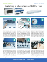
The electronics system of the CT-9500 Series Cross-Trainers, is made up of three distinct modules, the Power
Entry Module, the Display Console, and the Power Control Board.
120 volts AC enters the Power Entry Module. It passes through a transformer and is converted to 14 volts AC.
The 14 volts AC is applied to the Power Control Board at connector J4, pins 1 and 2. The voltage passes through a
bridge rectifier, BR1 and is converted to an unregulated positive DC voltage. This unregulated voltage will vary
from 11 volts DC to 18 volts DC depending on the wall supply and load. This voltage can be measured by placing
the positive probe of your DVM on Positive Test Point at BR1 and the negative probe on the negative Test Point at
BR1.
The other voltage developed on the Power Control Board is a regulated positive 8 volts DC. The regulated 8 volts
DC is developed by transistor (Q2) . This voltage can be measured by placing the positive probe of your DVM on
the collector(case) of Q2 and the negative probe on the anode of D1.
This 8 volts DC is supplied to the Console at connector J1, pin 4 and is used to power the LED’s. The 8 volts DC is
also used as a supply voltage for the positive 5 volt DC regulator (U1) on the Console board, which is VCC for the
Microprocessor. The Keypad entry (user’s input), Life Pulse (9500HR only), Telemetry, and the Stop Switch
functions are all processed by the Microprocessor.
The Console, by pulse width modulating the field control line, sends a signal to the Power Control Board at J1, pin
1. The Power Control Board switches the field current to the Alternator, through Q1. This field current along with
the energy supplied by the user is sent to the Load Resistors. This places resistance on the rotation, thus providing
the load sensation felt by the user.
The Alternator also provides the source for the RPM sensor circuit. The AC tap output on the Alternator enters the
Power Control Board at J2, pin 3. This AC voltage is wave conditioned and outputted at connector J1, pin 2 to the
Console connector P2, pin 6. Where it is processed and displayed by the Console.
PIN_PADSTA
CK
PIN
_P
AD
STA
CK
PIN_PADSTA
CK
PIN_PADSTA
CK
PIN_PADSTA
CK
PIN_PADSTA
CK
PIN_PADSTA
CK
PIN_PADSTA
CK
PIN_PADSTA
CK
PIN_PADSTA
CK
PIN_PADSTA
CK
C
O
MP
O
NE
NT
PIN_PADSTA
CK
PIN
_P
AD
STA
CK
PIN
_P
AD
STA
CK
PIN
_P
AD
STA
CK
PIN
_P
AD
STA
CK
PIN
_P
AD
STA
CK
C
O
MP
O
NE
NT
PIN_PADSTA
CK
PIN
_P
AD
STA
CK
PIN
_P
AD
STA
CK
PIN
_P
AD
STA
CK
PIN
_P
AD
STA
CK
PIN_PADSTA
CK
PIN
_P
AD
STA
CK
PIN
_P
AD
STA
CK
PIN
_P
AD
STA
CK
PIN
_P
AD
STA
CK
PIN_PADSTA
CK
PIN
_P
AD
STA
CK
PIN
_P
AD
STA
CK
PIN
_P
AD
STA
CK
PIN
_P
AD
STA
CK
PIN
_P
AD
STA
CK
PIN
_P
AD
STA
CK
PIN
_P
AD
STA
CK
PIN
_P
AD
STA
CK
PIN
_P
AD
STA
CK
PIN
_P
AD
STA
CK
PIN
_P
AD
STA
CK
PIN
_P
AD
STA
CK
PIN
_P
AD
STA
CK
PIN
_P
AD
STA
CK
PIN
_P
AD
STA
CK
PIN
_P
AD
STA
CK
PIN
_P
AD
STA
CK
PIN
_P
AD
STA
CK
PIN
_P
AD
STA
CK
PIN
_P
AD
STA
CK
PIN
_P
AD
STA
CK
PIN
_P
AD
STA
CK
PIN
_P
AD
STA
CK
PIN_PADSTA
CK
PIN
_P
AD
STA
CK
PIN
_P
AD
STA
CK
C
O
MP
O
NE
NT
PIN
_P
AD
STA
CK
C
O
MP
O
NE
NT
PIN
_P
AD
STA
CK
C
O
MP
O
NE
NT
PIN
_P
AD
STA
CK
C
O
MP
O
NE
NT
C
O
MP
O
NE
NT
C
O
MP
O
NE
NT
C
O
MP
O
NE
NT
1
C6
FU
SE
1
BR1
U3
HS3
HS1
HS4
C9
C5
Q1
D7
D6
J4
R9
R2
R1
R6R16
R4
R5
R15
R3
R14
R7
R8
R17
R18
C11
C14
C12
C13
C7
C8
U1
AC
POS
AC
WARNING:
RISK OF FIRE,REPLACE FUSE AS
MARKED.
Q2
C
1997
A080-92167-
A000
LIFE FITNESS
8
AM
P
S.B
.
25
0V
Neg
Q2
Pos
J4
14 VAC
8 VDC
+
_
D1
Neg
+
_
BR 1
18 VDC
J1
J2
ALTERNATOR
CONSOLE
Pin 3
RPM
Pin 4
8VDC
See Wiring Diagram for more detailed
information

Life Fitness Model 9500 Series Cross-Trainers
TABLE OF CONTENTS
SECTION I
TROUBLESHOOTING GUIDES PAGE
LOUD THUMPING NOISE............................................................................................... 2
RUBBING AND WHINNING NOISE................................................................................. 2
METAL NOISE................................................................................................................. 2
GRINDING....................................................................................................................... 2
RUBBING AND SQUEAKING .......................................................................................... 2
KNOCKING AND THUMPING.......................................................................................... 2
DRIVE BELT SLIPPING................................................................................................... 2
UPPER ARMS LOOSE.................................................................................................... 2
END PLAY IN PEADAL ARM........................................................................................... 3
ALTERNATOR BELT SLIPPING...................................................................................... 3
NO POWER..................................................................................................................... 3
NOT READING HEART RATE......................................................................................... 3
ERRATIC HEART RATE.................................................................................................. 4
NO LEDS......................................................................................................................... 4
NO RPM .......................................................................................................................... 4
ALTERNATOR BELT TENSION ...................................................................................... 5
NO LOAD......................................................................................................................... 6
SECTION II
DIAGNOSTICS
OVERVIEW ..................................................................................................................... 2
STATE 1: ALL LEDS AND KEYPAD TEST ...................................................................... 3
STATE 2: INDIVIDUAL LED TEST................................................................................... 4
STATE 3: PROGRAM VERSION NUMBER ............................................................................ 5
STATE 3: VERSION #, RPM, HR, AND LOAD TESTS (INTEGRATED PCB) .................. 6
STATE 4: HEART RATE SOFWARE (MODEL 9500HR ONLY)....................................... 7
STATE 4: LIFEPULSE AND NETWORK STATUS TESTS (INTEGRATED PCB)............. 8
STATE 5: MAXIMUM PROGRAM DURATION................................................................. 9
STATE 6: TELEMETRY ENABLE/DISABLE..................................................................... 10
STATE 7: ENGLISH / METRIC UNITS............................................................................. 11
STATE 8: MODEL SELECTION....................................................................................... 12
STATE 9: TOTAL HOURS / STATISTICS........................................................................ 13
STATE 10: METS ENABLE / DISABLE............................................................................ 14
STATE 11: PAUSE TIME OUT ........................................................................................ 15
STATE 12: PHOTO SHOOT............................................................................................ 16
STATE 12: LANGUAGE SELECTION (INTEGRATED PCB)............................................ 17
STATE 13: EEPROM TEST (INTEGRATED PCB)........................................................... 18
STATE 14: PHOTO SHOOT (INTEGRATED PCB).......................................................... 19
NOTES............................................................................................................................20

Life Fitness Model 9500 Series Cross-Trainers
TABLE OF CONTENTS
SECTION III
HOW T0…REPLACE: PAGE
DISPLAY CONSOLE ASSEMBLY.................................................................................... 2
TRAY ASSEMBLY........................................................................................................... 3
READING RACK ASSEMBLY.......................................................................................... 4
STOP SWITCH ASSEMBLY............................................................................................ 5
HOOD SHROUD ASSEMBLY.......................................................................................... 6
HEART RATE UPPER ARM ASSEMBLY......................................................................... 7
UPPER ARM ASSEMBLY................................................................................................ 8
RIGHT SIDE SHROUD FOR HEART RATE UNITS......................................................... 9
RIGHT SIDE SHROUD FOR NON-HEART RATE UNITS................................................ 10
IDLER PULLEY TENSION BRACKET.............................................................................. 11
DRIVE BELT.................................................................................................................... 12
POWER CONTROL BOARD BRACKET ASSEMBLY...................................................... 14
ALTERNATOR................................................................................................................. 15
ALTERNATOR BELT....................................................................................................... 16
PEDAL LEVER ASSEMBLY............................................................................................. 17
POWER MODULE ASSEMBLY....................................................................................... 18
CRANK SHAFT PULLEY ASSEMBLY .............................................................................19
INTERMEDIATE PULLEY ASSEMBLY............................................................................ 20
SECTION IV
ELECTRONICS OVERVIEW AND WIRING BLOCK DIAGRAMS
DISPLAY CONSOLE BOARD (DSP HEART RATE PCB)................................................2
DISPLAY CONSOLE BOARD (INTEGRATED PCB)........................................................ 4
ALTERNATOR CONTROL BOARD ................................................................................. 6
ALTERNATOR................................................................................................................. 7
WIRING BLOCK DIAGRAM FOR DSP HEART RATE BOARD........................................ 8
WIRING BLOCK DIAGRAM FOR INTEGRATED PCB..................................................... 9
NOTES............................................................................................................................10
SECTION V
PARTS IDENTIFICATION
MODEL ID AND SN LOCATION...................................................................................... 2
GK53-00012-XXXX SN 669724 - UP................................................................................ 3
GK53-00014-XXXX SN 665000 - 669723 .........................................................................5
GK53-00013-XXXX SN 685000 - UP................................................................................ 7
CT95-0XXX-18 SN 693097 - UP....................................................................................... 9
NOTES............................................................................................................................ 11
SECTION VI
MISCELLANEOUS INFORMATION
PREVENTIVE MAINTENANCE TIPS............................................................................... 2
UNPACKING INSTRUCTIONS ........................................................................................ 3
COMMUNICATING BY FAX.............................................................................................4
FAX FORM...................................................................................................................... 5
NOTES............................................................................................................................ 6

© 2000 Life Fitness, a division of Brunswick Corporation. All rights reserved. All rights reserved. Life Fitness, Lifecycle, Lifepulse and Flexdeck are registered
trademarks, and Heart Rate Zone Training, Lifespring and RELY ON IT are trademarks of Brunswick Corporation. Polar is a registered trademark of Polar. Any
use of these trademarks, without the express written consent of Life Fitness or the corresponding companies is forbidden.
M051-00K53-B011
11-2000

1
Life Fitness Model 9500 Series Cross-Trainers
SECTION I
TROUBLESHOOTING
GUIDES
Section I

2
Life Fitness Model 9500 Series Cross-Trainers
Malfunction Probable Cause Corrective Action
Loud thumping noise when
pedal levers rotate under load.
Pulleys misaligned. Loosen the pillow block bearing, align the
pulleys and then retighten the pillow block
bearings.
Rubbing/whining noise when
pulleys are rotating.
Dirt build up in pedal rails. Clean and remove dirt build up.
Rear roller wheels frozen. Clean and lubricate with non detergent oil.
Link or Pedal Lever is
contacting heatshield.
Reposition heat shield or replace.
Metal noise on rotation. Faulty intermediate shaft
assembly.
Replace intermediate shaft assembly.
Grinding. Faulty pillow block. Replace pilow blocks on crankshaft.
Alternator. Relieve tension on alternator, spin flywheel for
smoothness. If thumping occurs, faulty
alternator. Replace alternator.
Rubbing/squeaking. Bearings at pivot points out of
position or dirty.
Clean all sleeves in the linkage pivot areas and
lubricate with non detergent oil.
Knock/thumping occurs 180°
apart in rotation.
Setscrews in crank arm
assembly are loose.
Loosen setscrew and clamping screw in crank
arm assembly. Place blue Locktite
®
(242) on
screws. Tighten setscrew first to set keyway,
then tighten clamping screw.
Small extension arm bolt
loose.
Replace small extension arm kit.
Link or Pedal Lever is
contacting the heat shield.
Reposition or replace the heat shield.
Drive Belt slipping. Loose or worn drive belt. Adjust the tension on the idler pulley tension
bolt of the U-Tension Bracket (See How To...).
Rotate pulley and check the tension. Belt
tension should be 170 FT LBS for new belt and
160 FT LBS if installing existing belt. If a J10
belt gauge is not available. Adjust to a 1/4”
(7mm) deflection.
Upper Arms slip. Bolts that connect the upper
and lower arms is loose.
Adjust and tighten to a torque of 105 FT. LBS.

3
Life Fitness Model 9500 Series Cross-Trainers
Malfunction Probable Cause Corrective Action
Front to back play in pedal /
arm.
Worn bearings. Check for front to back movement in bearings
that connect pedal lever and crank arm or in
the 14” link.
Replace linkage bearing assembly.
Poly-V pulley on intermediate
shaft is loose.
Replace intermediate shaft assembly
(See How To...).
Crank Arm is loose. Loosen set screws and clamping screw in
Crank arm Assembly. Place blue Locktite
®
242
on screws. Tighten set screws first and then
tighten the clamping screw.
Alternator belt slipping. Loose or worn alternator belt Inspect for damage: replace alternator belt if
necessary. Adjust tension (See How To...).
Verify unit is turned on. Turn on at the ON/OFF switch.
Line cord damaged. Inspect AC line cord, verify no damage.
Damaged cable. Inspect all cables for damage.
Circuit breaker blown. Reset circuit breakers. Replace if needed.
Fuse on control board is blown. Replace control board.
Faulty entry module. Using a voltmeter, verify 14 v AC is at J4 on the
power control board.
Replace entry module.
No Power.
Faulty power control board. Using a voltmeter, verify 8 V DC at J1 pin 4 and
7 (see wiring diagram).
Cable connection. Disconnect and reconnect display console
cable connection
Pinched cable in RT/LT side. Remove shroud caps and inspect cables.
Replace damaged cable.
Inspect cable to make sure the right side cable
is on the users right, and the left is on the left
side.
Not reading heart rate.
Not communicating with DSP
board.
Enter diagnostic, see if DSP and monitor
version are displayed. If not displayed, replace
DSP board.
Section I

4
Life Fitness Model 9500 Series Cross-Trainers
Malfunction Probable Cause Corrective Action
Erratic heart rate. User’s hands are not making
proper contact.
Verify hands are contacting entire sensors.
Sweat is causing hands to slip Wipe hands and sensors.
Bad connection. Sensor loose or falling off. Replace Life Pulse
digital sensor with kit.
Remove handlebar shroud caps and verify cable
connection.
Cross talk from telemetry
receiver.
Verify position of Cross-Trainer is proper
distance from other telemetry equipped
equipment. See installation instructions or
operation manual.
Turn telemetry off from diagnostics and test Life
Pulse sensor separately.
Check for corrosion on connectors. Disconnect
and connect telemetry receiver.
Call Customer Support Service.
No LED. Cable connection. Remove display console and verify cable is
properly plugged into console.
8 vdc supply for LED. Using a voltmeter, measure for 8 vdc at console
cable connection. See wiring diagram for pin
configuration.
8 vdc supply not present at
cable.
Using, measure for 8 vdc at power control
board connection, J1. See wiring diagram pin
configuration.
No 8 vdc at J1. Faulty power control board. Replace power
control board.
No RPM. Unit shuts off one
minute into program.
Bad cable connection. Verify cables connections at console to PCB
(J1), and PCB to alternator (J2). Disconnect
and re-connect cables.
Using a voltmeter, verify cable continuity on
console to PCB and PCB to alternator.

5
Life Fitness Model 9500 Series Cross-Trainers
Malfunction Probable Cause Corrective Action
Alternator belt tension. Loose alternator belt. Check tension. New belt should be tensioned
to 90 FT LBS. Existing belt at 80 FT LBS. If
gauges are not available, set to 1/4” (6mm)
deflection.
Faulty alternator. Enter diagnostic to the field duty cycle and
increase the load. If load does not increase,
replace alternator.
Section I

6
Life Fitness Model 9500 Series Cross-Trainers

1
Life Fitness Model 9500 Series Cross-Trainers
SECTION II
DIAGNOSTIC MODES

2
Life Fitness Model 9500 Series Cross-Trainers
OVERVIEW
To access Diagnostic State 1, press and hold down
the number 5 key while pressing the CLEAR/PAUSE
key twice.
Press the START/ENTER key to scroll forward
through each programs. Press the CLEAR/PAUSE
key to scroll back to a previous program or to exit
when back in Diagnostic State 1.
To exit Diagnostics, press the CLEAR/PAUSE key to
return back to Diagnostic State 1, then press
CLEAR/PAUSE again to exit back to the user
display.
To verify the LifePulse ELECTRODES are
functioning, grasp each handlebar and begin to stride.
The heart-shaped LED will illuminate followed by the
heart rate reading.
FIELD DUTY CYCLE and ALTERNATOR TEST:
The FIELD DUTY CYCLE is displayed in the
CALORIES/HOUR window. The field duty cycle
ranges between 6 and 100. Adjust to the appropriate
value using the UP ARROW to increase or the
DOWN ARROW to decrease. To test the
ALTERNATOR, increase the field duty cycle to a
higher number. The tension should increase. When
testing is completed, use the DOWN ARROW to
return the field duty cycle to six.
To test the alternator, increase the field duty cycle
value using the up arrow, or down arrow to decrease
the field duty cycle value.
HEART RATE PROGRAM: The heart rate program
version is displayed in the ELAPSED TIME window
while the heart rate DSP version is displayed in the
SPEED window.
LIFECENTER MESSAGES are visible In the
CAL/HOUR window and appear as follows:
CAL/HOUR DESCRIPTION
NONE No LIFELINK board detected
NULL Board detected but not communicating
ON Linked to LIFECENTER
OFF Linked to LIFECENTER
PROGRAM DURATION: To set the program
duration, press the START/ENTER key. Use the UP
ARROW to increase time and the DOWN ARROW
to decrease time. Times can be set from 10 to 99
minutes.
TELEMETRY: Press the UP/DOWN ARROW to
toggle telemetry ON and OFF.
ENGLISH or METRIC SYSTEMS: Use the DOWN
ARROW to select METRIC and the UP ARROW to
select ENGLISH. The factory default is English.
PROGRAM HOURS: To show cumulative hours for
each program, press the UP ARROW key to scroll
forward through each program. Use the DOWN
ARROW to scroll backwards through each program.
PAUSE TIMES: The pause time feature can be set
between 1 and 99 minutes. The default is set at one
minute. Use the UP ARROW to increase pause
times and the DOWN ARROW to decrease pause
times in 1 minute increments.

3
Life Fitness Model 9500 Series Cross-Trainers
DIAGNOSTIC STATE 1 - ALL LEDs AND KEYPAD TEST
To access Diagnostic State 1, press and hold down the number 5 key while pressing the CLEAR/PAUSE key twice.
All the LEDs should illuminate on the status displays. Pressing each numeric key will display its value across the
status screen. For example: press the number 8 key to display 8’s across the screen.
Pressing the DISPLAY LOCK key, the letter ‘L’ appears across the status display. Pressing the AEROBICS key
displays the letter ‘A’, pressing the REVERSE key displays the letter ‘R’, pressing the QUICK START key displays
the letter ‘Q’, pressing the UP ARROW displays the letter ‘U’, and the DOWN ARROW displays the letter ‘D’.
Press the START/ENTER key to scroll forward to the next Diagnostic State, or press the CLEAR/PAUSE key to
exit diagnostics and return back to the user display.
Proceed to Diagnostic State 2 by pressing the START/ENTER key.
NOTICE: Each time a key is pressed it sounds a beep.
KEYS DISPLAY KEYS DISPLAY
0 0 8 8
1 1 9 9
2 2 Display Lock L
3 3 Aerobics Mode A
4 4 Reverse Mode R
5 5 Quick Start Q
6 6 Up U
7 7 Down D
Section II

4
Life Fitness Model 9500 Series Cross-Trainers
DIAGNOSTIC STATE 2 - INDIVIDUAL LED TEST
This test will show the LEDs for each display segment (Time, Speed RPM, Level, Heart Rate, Calories, Distance,
CAL/Watts, and Watts) for proper illumination.
Press the START/ENTER key to scroll forward to the next Diagnostic State or press the CLEAR/PAUSE key to
scroll backward to Diagnostic State 1.
To exit diagnostics, press the CLEAR/PAUSE key when in Diagnostic State 1 to get back to the user display.
Proceed to Diagnostic State 3 by pressing the START/ENTER key.

5
P 3 . 1 1
6
Life Fitness Model 9500 Series Cross-Trainers
DIAGNOSTIC STATE 3 - PROGRAM VERSION NUMBER
The current PROGRAM VERSION NUMBER (ex: P285) will be displayed in the TIME window. While striding, the
RPM will be displayed in the RPM window, and while holding the handlebar sensors or wearing an optional
telemetry heart rate chest strap, the HEART RATE will be displayed in the LEVEL window.
The FIELD DUTY CYCLE LOAD TEST/ALTERNATOR is displayed in the CAL/HOUR window. Field duty cycle
settings are set between 6 to 100. The greater the number, the greater the resistance. To adjust in increments of
‘1’ press the number 1 key to decrease resistance and the number 3 key to increase resistance. To adjust in
increments of 10, press the number 4 key to decrease resistance and the number 6 key to increase resistance.
To test the alternator, verify that when increasing the FDC, the resistance increases.
NOTE: AFTER TESTING, THE FDC MUST BE SET BACK TO THE FACTORY SETTING OF 6.
Press the START/ENTER key to scroll forward to the next Diagnostic State or press the CLEAR/PAUSE key to
scroll backward to a previous program.
To exit diagnostics, press the CLEAR/PAUSE key through the previous Diagnostic States to get back to the user
display.
Proceed to Diagnostic State 4 by pressing the START/ENTER key.
Section II

6
P1.20 REDY 6
CT
Life Fitness Model 9500 Series Cross-Trainers
DIAGNOSTICS STATE 3 - VERSION #: RPM, HR, and LOAD TESTS w/ Integrated PCB
The PROGRAM VERSION NUMBER (ex. P1.01) will be displayed in the ELAPSED TIME window.
The present RPM will be displayed in the RPM window.
The NETWORK STATUS will be displayed in the LEVEL/CALORIES window.
The present FIELD DUTY CYCLE applied to the alternator will be displayed in the CALORIES/HOUR
window. This value can be adjusted using the ‘DOWN’ and ‘UP’ keys to decrement and increment the
FIELD DUTY CYCLE. The FIELD DUTY CYCLE can also be adjusted down or up in increments of 10
using the ‘4’ and ‘6’ keys.
Pressing the ‘8’ key will toggle the display of the LIFEFITNESS PART # of the console software.
Pressing the ‘9’ key will toggle the display of the CSAFE version number.
Pressing the ‘CLEAR/PAUSE’ key will return to DIAGNOSTICS STATE 2.
Pressing the ‘START/ENTER’ key will advance to DIAGNOSTICS STATE 4.

7
P1.80 P4.00
NONE
Life Fitness Model 9500 Series Cross-Trainers
DIAGNOSTIC STATE 4 - HEART RATE SOFTWARE (Model 9500HR ONLY)
The PROGRAM VERSION NUMBER (P1.80) of the HEART RATE DSP board software is displayed in the
ELAPSED TIME window.
The PROGRAM VERSION NUMBER (P4.00) of the HEART RATE DSP board DSP software is displayed in the
SPEED window.
The display of both PROGRAM VERSION NUMBERS verifies that the HEART RATE DSP board is functioning
properly.
The status of the LIFELINK board and LIFECENTER connection are displayed in the CAL/HOUR window. The
following conditions are as follow:
CAL/HOUR DESCRIPTION
NONE No LIFELINK board detected
NULL Board detected but not communicating
ON Linked to LIFECENTER
OFF Linked to LIFECENTER
To test the sensors, grasp the sensors making sure proper contact is maintained. The heart shaped LED will light
up and “HR” will appear when sensors are grasped. The heart rate reading will follow.
Press the START/ENTER key to scroll forward to the next Diagnostic State or press the CLEAR/PAUSE key to
scroll backward to previous programs.
To exit diagnostics, press the CLEAR/PAUSE key when in Diagnostic State 1 to get back to the user display.
Proceed to Diagnostic State 5 by pressing the START/ENTER key.
Section II

8
L P V E R S I O N
9.7
Life Fitness Model 9500 Series Cross-Trainers
DIAGNOSTICS STATE 4 - LIFEPULSE and NETWORK STATUS TESTS w/ Integrated
PCB
Upon entry to this diagnostic state, the LifePulse software version number is displayed for 2 seconds. After this,
the LP Comm Status is displayed for 2 seconds, which will either display ‘LP PC COMM ON’ or ‘LP PC COMM
OFF’. Make sure ‘LP PC COMM OFF’ appears, or CSAFE will not function correctly. The LP Comm Status can
be toggled by pressing the ‘5’ key during the 2 seconds when the LP Comm Status message is being displayed,
and does not normally need to be adjusted.
After these messages are done displaying, the LifePulse test information comes up.
A counter displaying the ELAPSED TIME since both hands were placed on the LifePulse sensors begins
counting in the TIME window. This counter will stop counting as soon as a heart rate is displayed.
The GAIN is displayed in the RPM window.
HEART RATE is displayed in the LEVEL/HEART RATE window.
The CONFIDENCE LEVEL between 0–9 is displayed in the CALORIES/HOUR window, with 0 indicating
the lowest confidence in the reported HEART RATE and 9 indicating the highest.
The profile window will display an ‘L’ when the left LifePulse sensor is being held,. An ‘R’ when the right
LifePulse sensor is being held, and ‘L’ and ‘R’ when both sensors are being held.
Pressing the ‘CLEAR/PAUSE’ key will return to DIAGNOSTICS STATE 3.
Pressing the ‘START/ENTER’ key will advance to DIAGNOSTICS STATE 5.
/