
412 021--001 9702
A6 PAK
Control system for motorised slides
Simplified service manual

LIST OF CONTENTS Page
TECHNICAL DESCRIPTION 4...................................
INSTALLATION 7...............................................
OPERATION 7.................................................
MAINTENANCE 7..............................................
DIMENSION DRAWING 8........................................
DIAGRAM 9....................................................
DIAGRAM 10....................................................
SPARE PARTS LIST A6 PAK 11...................................
Rights reserved to alter specifications without notice.

-- 3 --
mvarnen1
WARNING
ARC WELDING AND CUTTING CAN BE INJURIOUS TO YOURSELF AND OTHERS.
TAKE PRECAUTIONS WHEN WELDING. ASK FOR YOUR EMPLOYER’S SAFETY
PRACTICES WHICH SHOULD BE BASED ON MANUFACTURERS’ HAZARD DATA.
ELECTRIC SHOCK -- Can kill
S Install and earth the welding unit in accordance with applicable standards.
S Do not touch live electrical parts or electrodes with bare skin, wet gloves or
wet clothing.
S Insulate yourself from earth and the workpiece.
S Ensure your working stance is safe.
FUMES AND GASES -- Can be dangerous to health
S Keep your head out of the fumes.
S Use ventilation, extraction at the arc, or both, to keep fumes and gases from
your breathing zone and the general area.
ARC RAYS -- Can injure eyes and burn skin .
S Protect your eyes and body. Use the correct welding screen and filter lens
and wear protective clothing.
S Protect bystanders with suitable screens or curtains.
FIRE HAZARD
S Sparks (spatter) can cause fire. Make sure therefore that there are no
inflammable m aterials nearby.
MALFUNCTION
S Call for expert assistance in the event of malfunction.
READ AND UNDERSTAND THE INSTRUCTION MANUAL BEFORE
INSTALLING OR OPERATING THE EQUIPMENT
PROTECT YOURSELF AND OTHERS!

-- 4 --
cgb1d1ea
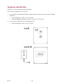
TECHNICAL DESCRIPTION
A6 PAK is a control system for motorised slides.
The system is available in two versions:
1. As a complete standard system with or without remote control unit for automatic welding
machines
S Joint tr acking unit, order no. 417 587--880
S Joint tracking unit with r emote control, order no. 417 587--882
2. As a build--in component for a column and boom
S Joint tr acking unit, order no. 417 587--881
agb1d003

-- 5 --
cgb1d1ea
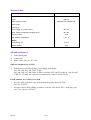
Technical d ata
Control system for motorised slides A6 PAK
Supply and control voltage 42V AC 50--60 Hz
Power 460 V A
Motor regulator , model Switched four quadrant reg.
Speed (high)
Speed (low)
Rotor voltage, Joy--stick control 40 V DC
Stator voltage, independent magnet motor 48 V DC
Enclosure class IP 53
Max. ambient temperature +45
_
C
Weight:
Joint tracking unit 4.5 kg
Remote control 2kg
A6 PAK consists of:
1. Joint tr acking unit
2. Control unit
3. Motor cable, order no. 417 310.
Optional equipment for A6 PAK
4. Transformer to provide separate power supply from mains
190, 220, 380, 415, 440, 500V 50 Hz
200, 230, 380, 415, 440, 500V 60 Hz to secondary 42V, 660 VA order no. 148 636--002.
Cable3x2.5mm
2
, for connection to transfor mer, order no. 2626 134--04.
ESAB standard servo slides for A6 PAK
S A6 servo slide, ball screw type with permanent magnet m otor 42 V DC,
order no. 334 333.
S A6 motor--driven slide, sliding on runners, with A6 VEC motor 42V -- 4000 rpm, gear
ratio 74:1, order no. 334 426.

-- 6 --
cgb1d1ea
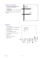
Controls and connections
1. Illuminated pushbutton, orange
For selection of high speed
2. Control lever
Manual operation of servo slides up/down
and left/right
Component position for joint t racking device,
seepage19.
Rear panel
1. Socket, 4 pin.
for connecting horizontal slide motor
2. Socket, 4 pin.
for connecting vertical slide motor
3. Socket, 23 pin.
for connecting control unit
4. Control fuses, 10 A slow (1 off)
5. 42 V supply
6. Switch
Supply voltage on/off
7. Spare socket

-- 7 --
cgb1d1ea
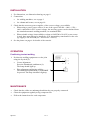
INSTALLATION
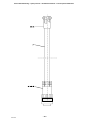
1. For dimensions, see dimension drawing on page 8.
2. Connections
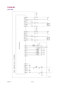
S for welding machines, see on page 9.
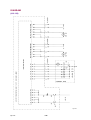
S for column and booms, see on page 10.
3. Check that the necessary power supplies, of the correct voltage, are available.
S When using a power power sources of one of the types LAE 800 -- 1000 -- 1250 --
1600, connected for 42 V control voltage, the necessary power can be obtained from
the standard automatic welding machine, see terminal PEG1.
S When suitable voltage is unavailable or when an L AH 500--630 42 V power source
is used, there must always be installed a 42 V intermediary transform er for the volt-
age supply to the A6 PAK (see “Accessories” section).
4. See the picture on page 6 for details of the controls.
OPERATION
Positioning to start welding
1. Position the welding equipment over the joint
using the Joystick (2).
S Coarse adjustment
Press the illuminated pushbutton (1).
The lamp should light up.
S Fine adjustment and during welding
The illuminated pushbutton (1) must NOT
be pressed. The lamp should not light up.
MAINTENANCE
S Check that the cables are undamaged and that they are properly connected.
S Clean the equipment regular ly using compressed air.
S Follow the instructions f o r each component.

dgb1m001
-- 8 --
cgb1d1ea
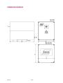
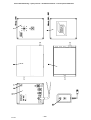
DIMENSION DRAWING

agb1e001
-- 9 --
cgb1d1ea
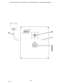
DIAGRAM
(418 138)

agb1e002
-- 1 0 --
cgb1d1ea
DIAGRAM
(418 139)

-- 1 1 --
A6PAK
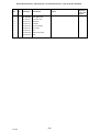
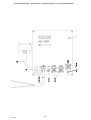
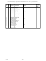
SPARE PARTS LIST A6 PAK
Edition 9702
Spare parts are to be ordered through the nearest ESAB agency as per the list
on the back of the cover. Kindly indicate type of unit, serial number,
denominations and ordering numbers according to the spare parts list.

Reservdelsförteckning -- Spare parts list -- Ersatzteilverzeichnis -- Liste de pècees détachèes
-- 1 2 --
s417587
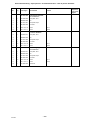
Item
Qty Orderingno. Denomination Remarks
Component
designation
in the circuit
diagram
417 587--880 Joint tracking equipment,
excl. control box
1 1 417 588--880 Cover plate, front
3 1 332 908--880 Box
4 1 417 591--881 Rear panel, compl
6 1 481 995--880 PC--board
7 8 2121 107--18 Screw B8x13
8 1 2117 107--17 Screw B8x9.5
417 587--881 Joint tracking equipment
for column and boom
2 1 416 060--001 Cover plate, front
3 1 332 908--880 Box
5 1 417 591--880 Rear panel, compl
6 1 481 995--880 PC--board
7 8 2121 107--18 Screw B8x13
8 1 2117 107--17 Screw B8x9.5
417 587--882 Joint tracking equipment,
incl. control box
2 1 416 060--001 Cover plate, front
3 1 332 908--880 Box
5 1 417 591--880 Rear panel, compl
6 1 481 995--880 PC--board
7 8 2121 107--18 Screw B8x13
8 1 2117 107--17 Screw B8x9.5
10 1 417 899--880 Control box

Reservdelsförteckning -- Spare parts list -- Ersatzteilverzeichnis -- Liste de pècees détachèes
-- 1 3 --
s417587

Reservdelsförteckning -- Spare parts list -- Ersatzteilverzeichnis -- Liste de pècees détachèes
-- 1 4 --
s417588
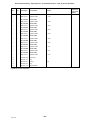
Item
Qty Orderingno. Denomination Remarks
Component
designation
in the circuit
diagram
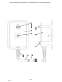
417 588--880 Cover plate, front
1 417 590--001 Cover plate, front
2 415 302--001 Manipulator
3 415 200--001 Pushbutton
4 415 200--020 Switch mechanism
5 415 200--027 Cap, orange
6 415 200--047 Bulb
7 415 200--058 Splash shield (water)
8 433 070--002 Cable

Reservdelsförteckning -- Spare parts list -- Ersatzteilverzeichnis -- Liste de pècees détachèes
-- 1 5 --
s417588

Reservdelsförteckning -- Spare parts list -- Ersatzteilverzeichnis -- Liste de pècees détachèes
-- 1 6 --
s417591
Item
Qty Orderingno. Denomination Remarks
Component
designation
in the circuit
diagram
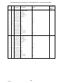
417 591--880 Rear panel, compl
1 1 417 593--001 Rear panel
2 1 193 701--001 Fuse holder
3 1 567 900--107 Quick--blow fuse
4 1 193 701--002 Fuse holder
5 1 267 101--301 Fitting
6 2 2126 022--06 Nut Pr 15,2
7 1 2129 101--06 Plug
8 20 2121 088--23 Screw M3x6
9 20 2126 011--03 Nut M3
10 2 418 142--880 Cable
11 1 418 141--880 Cable
12 1 193 317--001 Switch
13 1 2626 134--01 Cable
14 1 193 319--801 Flat--pin sleeve
15 1 323 941--002 Sleeve socket 8--pol.
16 1 418 140--880 Cable
417 591--881 Rear panel, compl
1 1 417 593--001 Rear panel
2 1 193 701--001 Fuse holder
3 1 567 900--107 Quick--blow fuse
4 1 193 701--002 Fuse holder
5 1 267 101--301 Fitting
6 2 2126 022--06 Nut Pr 15,2
7 1 2129 101--06 Plug
8 20 2121 088--23 Screw M3x6
9 20 2126 011--03 Nut M3
10 2 418 142--880 Cable
12 1 193 317--001 Switch
13 1 2626 134--01 Cable
14 1 193 319--801 Flat--pin sleeve
15 1 323 941--002 Sleeve socket 8--pol.
16 1 418 140--880 Cable

Reservdelsförteckning -- Spare parts list -- Ersatzteilverzeichnis -- Liste de pècees détachèes
-- 1 7 --
s417591

Reservdelsförteckning -- Spare parts list -- Ersatzteilverzeichnis -- Liste de pècees détachèes
-- 1 8 --
s417899
Item
Qty Orderingno. Denomination Remarks
Component
designation
in the circuit
diagram
417 899--880 Control box
1 415 200--001 Pushbutton
2 415 200--020 Switch mechanism
3 415 200--027 Cap, orange
4 191 953--101 Cable 0,25 mm
2
5 415 200--047 Bulb
6 415 200--058 Splash shield (water)
7 417 901--001 Plate
8 415 302--001 Manipulator
9 332 556--001 Protective clamp
10 2121 080--45 Screw M4x12
11 2126 01 1--05 Nut M4
12 417 900--001 Apparatus box
13 193 307--104 Cable fitting
14 2126 022--08 Nut
15 191 812--104 Cable
16 368 541--002 Pin plug 23 pol
17 161 337--051 Box
18 2126 011--06 Nut M5

Reservdelsförteckning -- Spare parts list -- Ersatzteilverzeichnis -- Liste de pècees détachèes
-- 1 9 --
s417899

Reservdelsförteckning -- Spare parts list -- Ersatzteilverzeichnis -- Liste de pècees détachèes
-- 2 0 --
s417310
Item
Qty Orderingno. Denomination Remarks
Component
designation
in the circuit
diagram
417 310--880 Control cable *)
1 2626 134--01 Apparatus cable L=19m
417 310--881 Control cable *)
1 2626 134--01 Apparatus cable L=22m
417 310--882 Control cable *)
1 2626 134--01 Apparatus cable L=25m
417 310--883 Control cable *)
1 2626 134--01 Apparatus cable L=28m
417 310--884 Control cable *)
1 2626 134--01 Apparatus cable L=32m
417 310--885 Control cable *)
1 2626 134--01 Apparatus cable L=36m
417 310--886 Control cable *)
1 2626 134--01 Apparatus cable L=40m
417 310--887 Control cable *)
1 2626 134--01 Apparatus cable L=2m
417 310--888 Control cable *)
1 2626 134--01 Apparatus cable L=5m
417 310--889 Control cable *)
1 2626 134--01 Apparatus cable L=10m
2 192 784--002 Sleeve plug
3 192 784--101 Plug
4 323 942--001 Pin plug 4--pol
5 323 945--001 Plug
6 323 943--102 Counterbalance
*) Additional system components
Page is loading ...
Page is loading ...
-
 1
1
-
 2
2
-
 3
3
-
 4
4
-
 5
5
-
 6
6
-
 7
7
-
 8
8
-
 9
9
-
 10
10
-
 11
11
-
 12
12
-
 13
13
-
 14
14
-
 15
15
-
 16
16
-
 17
17
-
 18
18
-
 19
19
-
 20
20
-
 21
21
-
 22
22


