Page is loading ...

126583.PDF
2011 SCALPEL.
OWNER’S MANUAL SUPPLEMENT.
OWNER’S MANUAL SUPPLEMENT.
2011 SCALPEL.
OWNER’S MANUAL SUPPLEMENT.

1
126583.PDF
SAFETY INFORMATION
IMPORTANT COMPOSITES MESSAGE
WARNING
Your bike (frame and components) is made from composite
materials also known as “carbon ber.”
All riders must understand a fundamental reality
of composites. Composite materials constructed of
carbon bers are strong and light, but when crashed or
overloaded, carbon bers do not bend, they break.
For your safety, as you own and use the bike, you must
follow proper service, maintenance, and inspection of all
the composites (frame, stem, fork, handlebar, seat post,
etc.) Ask your Cannondale Dealer for help.
We urge you to read PART II, Section D. “Inspect For Safety”
in your Cannondale Bicycle Owner’s Manual BEFORE you
ride.
YOU CAN BE SEVERELY INJURED, PARALYZED OR KILLED
IN AN ACCIDENT IF YOU IGNORE THIS MESSAGE.
BICYCLE REPAIR / WORK STANDS
The clamping jaws of a bike stand can generate a crushing force
strong enough to seriously damage your frame.
NOTICE
Never place your bike in a bike stand by clamping the frame.
Place your bike in a stand by extending the seat post and
positioning the stand clamp on the extended seat post. Don’t
extend beyond the MINIMUM INSERT line marked on the seat post.
Since your carbon seat post can also be damaged by clamping
force, adjust the stand clamp for the minimum clamping force
needed to secure the bike.
Also, before clamping, clean the post and protect the seat post
nish with a rag.
If you have an old un-used seat post, use it instead of your regular
post to mount your bike in a stand.
INSPECTION & CRASH DAMAGE OF
CARBON FRAMES/FORKS
WARNING
AFTER A CRASH OR IMPACT:
Inspect frame carefully for damage (See PART II, Section
D. Inspect For Safety in your Cannondale Bicycle Owner’s
Manual. )
Do not ride your bike if you see any sign of damage, such as
broken, splintered, or delaminated carbon ber.
ANY OF THE FOLLOWING MAY INDICATE A
DELAMINATION OR DAMAGE:
■ An unusual or strange feel to the frame
■ Carbon which has a soft feel or altered shape
■ Creaking or other unexplained noises,
■ Visible cracks, a white or milky color present in carbon
ber section
Continuing to ride a damaged frame increases the
chances of frame failure, with the possibility of
injury or death of the rider.
INTENDED USE
WARNING
UNDERSTAND YOUR BIKE AND ITS INTENDED USE.
USING YOUR BIKE THE WRONG WAY IS DANGEROUS.
Industry usage Conditions 1 - 5 are generalized and evolving.
Consult your Cannondale Dealer about how you intend to use your
bike.
Please read your Cannondale Bicycle Owner’s Manual for
more information about Intended Use and Conditions 1-5.
OBSERVE THE “INTENDED USE” FOR YOUR BIKE FOUND IN THE
GEOMETRY/ SPECIFICATIONS SECTION OF THIS SUPPLEMENT.

2
MAXIMUM FORK LENGTH
Maximum Fork Length is an important frame safety testing
specication. You must observe the measurement when
installing headset parts, headset adapters, installing and
adjusting a fork, and selecting replacement forks. In this
manual, the number is also listed in the GEOMETRY/
SPECIFICATIONS.
HEADTUBE
HEADSET
PARTS or
ADAPTERS
AXLE
MAXIMUM FORK LENGTH
HOW TO MEASURE: 1. Install headset and fork. 2. Extend
fork and measure the distance from the bottom of the head
tube to the center of the wheel axle. Do not measure from
the bottom of headset bearing cups or head tube adapters.
The measurement MUST be taken from the bottom of the head
tube!!
WARNING
DO NOT EXCEED MAXIMUM FORK LENGTH
Exceeding the MAXIMUM FORK LENGTH limit can overload
the frame causing it to fail (break) while riding.
YOU CAN BE SEVERELY INJURED, PARALYZED OR KILLED
IN AN ACCIDENT IF YOU IGNORE THIS WARNING.
TIRE SIZE
WARNING
OBSERVE THE “MAXIMUM TIRE WIDTH” FOR YOUR
BIKE FOUND IN THE GEOMETRY/ SPECIFICATIONS
SECTION OF THIS SUPPLEMENT.
Mounting the wrong size tires can result in the tires hitting
the fork or frame when riding. If this happens, you can lose
control of your bike and you can be thrown o, a moving
tire can be stopped because it touches the fork or frame.
Do not mount oversized tires, ones that rub or hit the fork
or frame, ones that result in too little clearance, or ones
that can hit the fork or frame when the suspension is fully
compressed or when riding.
Take care that the tires you select are compatible with
your bike’s fork or frame design. Also, be sure to follow the
manufacturer’s recommendations of your front fork and
rear shocks.
When you are considering tires for your bike consider...
The actual measured size of a tire may be dierent than
its sidewall marking. Each time you mount a new tire,
take the time to inspect the actual clearance between the
rotating tire and all parts of the frame. The U.S. Consumer
Product Safety Commission (CPSC) requires at least 1/16”
(1.6 mm) tire clearance from any part of the bike. Allowing
for lateral rim ex and a wheel or rim that is out-of-true
will likely mean choosing a rear tire that provides even
more clearance than the CPSC recommends.
ASK YOUR CANNONDALE DEALER FOR THE RIGHT TIRES
FOR YOUR BIKE AND ITS PARTICULAR COMPONENTS!
YOU CAN BE SEVERELY INJURED, PARALYZED OR KILLED
IN AN ACCIDENT IF YOU IGNORE THIS WARNING.

126583.PDF
3
INTEGRATED HEAD TUBE
The following Cannondale headset kits can be used :
45° UP
45° DOWN
12 mm
- or -
1.125”
KP119/
INTEGRATED HEADSHOK TO 1.5
QSISEAL/
UPPER BEARING SEAL
58MM OD
HD169/
SI HEADSET
BEARINGS
HEADSHOK
1.5”
KP058/
INTEGRATED HEADSHOK TO 1 1/8
NOTICE
Cannondale Headshok System Integration bearings cups are permanently bonded in the head tube. When removing
adapters, bearings, extra care must be used so that the tool used to drive out the bearing is NOT located on any part of the
bonded cup.
Do not machine, cut, or use surfacing tools in the head tube.

4
BOTTOM BRACKET
The bottom bracket shell is compatible with the BB30 Standard. See http://www.bb30standard.com/ . The SI bottom bracket
adapter enables the use of standard English/73mm bottom bracket cranksets.
KB6180/ - STANDARD BEARING
KP018/ - CERAMIC BEARING
QC616/ - CIRCLIPS
Circlip Groove
BEARING MAINTENANCE
Inspect bearing condition annually (at a minimum) and anytime the crankset assembly is disassembled or serviced.
With the crankset removed, rotate the inner bearing race of both bearings; rotation should be smooth and quite with no bearing
play or movement inside the shell. If the bearing is damaged, replace both bearings with new ones.

126583.PDF
5
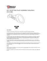
BEARING INSTALLATION
1. Clean the inside and outside surfaces of the bottom
bracket shell.
2. Apply a high-quality bicycle bearing grease to the inside
surface of the shell.
3. Install the square end of the circlip into the groove rst,
then moving clockwise, push the clip into the groove until
it is fully seated in the groove. Install the other circlip the
same way.
4. With a headset press, and Cannondale tool KT010/ install
the bearings into the shell as shown. Press the bearing
until it is seated against the circlip.
5. To nish, apply a light coating of a high-quality bicycle
bearing grease to both sides of each bearing to help repel
moisture.
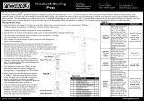
BEARING REMOVAL
1. To remove the bearings, position Cannondale tool KT011/
behind the bearing so that the tool ridges are seated on
the bearing. See next page.
2. Insert a driver (punch or drift) from the opposite side.
Locate it on the back of the tool and use light tapping to
drive the bearing from the shell.
NOTICE
Frequent or routine renewal of undamaged bearings is
not recommended. Repeated removal and reinstallation
can damage the inside BB shell surfaces resulting in poor
bearing t.
DO NOT FACE, MILL OR MACHINE THE
BOTTOM BRACKET SHELL FOR ANY REASON.
Doing so can result in serious damage and possibly a ruined
bike frame.
TIP: Unless a circlip is damaged, removal is unnecessary
during bearing removal . Use a small thin-blade screw
driver or pick to lift the hooked end up out of the groove and
then pushing the circlip out counter-clockwise.
KT010/
BEARING INSTALLATION TOOL
BEARING
BEARING
KT011/
BEARING DRIVER
Thin blade
screw driver
to lift hooked
out of BB groove

6
73mm ADAPTER INSTALLATION
The following procedure should only be completed by a professional bike mechanic. The adapter IS NOT a repair part
and will only work in undamaged frames in good condition.
1. Remove the BB30 bearings and circlips from the bottom bracket shell.
2. Thoroughly clean and dry the inside of the bottom bracket shell. Remove any grease or dirt. Use a clean lint-free shop towel
dampened with alcohol to nish.
3. Apply Loctite™ 609 carefully to the bearing seat positions on both side of the inside shell.
4. Clean the outer surface of the adapter. Use a clean shop towel dampened with alcohol.
5. The groove side of the adapter must be located on the drive side. With a headset press, press the ADAPTER until the groove side
face is ush with the drive side face of the SI BB shell.
Allow at least 12 hours (at 72°F) for the Loctite to cure before installing the standard bottom bracket crankset.
Follow Loctite Technical Data Sheet http://tds.loctite.com/tds5/docs/609-EN.PDF
Groove
KP010/
73 mm ADAPTER
DRIVE SIDE
(Headset press not shown)
KF368/
ADAPTER w/TOOL
Loctite™ 609
NOTICE
We strongly recommended that you use a swab to control the application and avoid spillage of the Loctite. Prolonged contact
with the frame nish may result in discoloration or damage. Be sure to immediately wipe up any spills and remove any
compound in contact with the painted surfaces.

126583.PDF
7
73mm ADAPTER REMOVAL
The following procedure should only be completed by a professional bike mechanic. The adapter is removable, how-
ever, repeated removal and reinstallation could result in damage to the SI BB shell and is not recommended.
1. Removal of the SI BB ADAPTER is accomplished through the use of the extraction tool KF366/ , a two-piece tool set used with
a headset bearing press. The arrangement of the tool parts for removal is shown next gure.
2. Press the adapter out of the shell using the headset press.
Following removal, it will be necessary to clean all remaining Loctite residue using Loctite 768. Use a dental pick to remove
any adhesive from the grooves. Do not cut, face, or use abrasives to clean the inside if the BB shell. For Loctite clean-up
instructions : http://tds.loctite.com/
(Headset press not shown)
KF366/
EXTRACTION TOOL
DRIVE SIDE
Receiver
Press
ADAPTERADAPTE
R
ADAPTER
NOTICE
Use only extraction tool Cannondale KF366/ and a headset press. Do not use other tools.
Make sure the Reciever part of the tool is centered on the drive side bottom bracket shell while pressing.
We strongly recommend that your have this procedure performed by an Authorized Cannondale Dealer. Damage caused by
improper removal is not covered under your warranty.

8
SEAT POST
MINIMUM SEAT POST INSERT DEPTH
The seat post must be inserted a minimum of 100 mm .
10
SEAT POST
(Saddle not shown)
SEAT TUBE
MINIMUM
SEAT POST
INSERT DEPTH
100mm
TOP TUBE
WARNING
MAKE SURE AT LEAST 100 mm OF THE SEAT POST IS
INSERTED INTO THE FRAME AT ALL TIMES. Failure to insert
the seat post correctly can place a very high stress on the
seat tube top tube junction causing the frame to break while
riding.
Measure 100 mm from the bottom of the seat post. Use
a permanent marker to mark the post at 100 mm. When
adjusting the seat post height in the seat tube, never adjust
the seat post so that the line you mark is above the top edge
of the seat tube.
YOU MUST ALSO BE AWARE THAT bicycle seat posts are
permanently marked by the manufacturer with a “MINIMUM
INSERT” line on the seat post itself. You must not rely on this
marking as an indication of the proper MINIMUM SEAT POST
INSERTION DEPTH.
YOU CAN BE SEVERELY INJURED, PARALYZED OR KILLED IN
AN ACCIDENT IF YOU IGNORE THIS WARNING.
Installation
1. Always clean the inside of the seat tube with a dry clean
shop towel.
2. Apply a generous amount carbon gel to the inside of the
clean seat tube and to the seat post. A small nylon brush
works well for spreading inside the seat tube.
3. Apply small amount of bicycle bearing grease to the area
under the binder on the seat tube. Reinstall the seat
binder. Be sure to align the binder pin with the seat
tube slot.
Pin
ALIGN
Slot
SEAT BINDER
Light grease
Carbon gel
5 Nm, 44 InLbs

126583.PDF
9
4. Insert the seat post, set saddle height, and tighten the
binder bolt to 5 Nm, 44 In Lbs.
NOTICE
NEVER USE SOLVENTS OR SPRAY CLEANERS.
DON’T USE GREASE; ALWAYS USE CARBON GEL.
Cannondale kit KF115/ is a small quantity, enough for two
or three applications.
NEVER FORCE THE SEAT POST INTO THE FRAME.
ALWAYS USE A TORQUE WRENCH.
TIP: When tightening the seat binder, also check the specied
tightening torques of the saddle to seat post clamp bolts.
TIP: Its a good idea to periodically remove the binder bolt, from
the binder, clean it threads and lightly grease the threads.

10
Please note that the specications and information in this manual are subject to change for product improvement.
For the latest product information, go to http://www.cannondale.com/tech_center/
GEOMETRY /SPECIFICATION
STACK
REACH
M
F
H
I
L
K
D
J
A
C
B
G
E
N
EYE-TO-EYE
GEOMETRY SMALL MEDIUM LARGE XLARGE
A Seat Tube Length (cm/in) 40.5/15.9 43.5/17.1 48.2/19.0 53.2/20.9
B Top Tube Horizontal (cm/in) 55.5/21.9 58.5/23.0 61.5/24.2 64.0/25.2
C Top Tube Actual (cm/in) 53.4/21.0 56.2/22.1 59.5/23.4 62.7/24.7
D Head Tube Angle 69.3 69.6 69.8 70.0
E Seat Tube Angle Eective 74.0
« « «
F Standover (cm/in) 75.9/29.9 75.7/29.8 75.4/29.7 75.4/29.7
G Head Tube Length - (cm/in) 13.4/5.3
« « «
H Wheelbase (cm/in) 107.4/42.3 110.0/43.3 112.8/44.4 115.1/45.3
I Front Center (cm/in) 65.0/25.6 67.7/26.6 70.4/27.7 72.7/28.6
J Chain Stay Length (cm/in) 42.4/16.7
« « «
K Bottom Bracket Drop (cm/in) 1.2/0.5
« « «
L Bottom Bracket Height (cm/in) 31.8/12.5
« « «
M Fork Rake (cm/in) 4.5/1.8
« « «
N Trail (cm/in) 7.7/3.0 7.5/2.9 7.4/2.9 7.2/2.8
STACK (mm/in) 561.5/22.1 562.8/22.2 563.7/22.2 564.6/22.2
REACH (mm/in) 394.0/15.5 423.6/16.7 453.4/17.8 478.1/18.8

126583.PDF
11
SPECIFICATION
Rear Travel 80 mm
Intended Use Condition 3, XC Racing
Maximum Tire Width 2.3 in
Maximum Fork Length 500 mm
Minimum Seat Post Insert 100 mm
Frame Material Carbon Composite
Seat Post Diameter 31.6 mm
Front Derailleur Direct Mount Type S3 (SRAM) or E-Type w/o BB plate (SHIMANO)
Headtube Integrated Headshok
Chainline 50 mm
BB Shell Width 73 mm
Dropout Spacing 135 mm
Rear Brake 140 mm Post Mount standard
REAR SHOCK
Eye-to-Eye 165 mm, (6.5 in)
Stroke 38 mm, (1.5 in)
Recommended Sag 20-25% 7 - 9 mm
Shock Bushing Width 21.8 mm (link side), 25.2 mm (frame side)
Shock Bolt Hole Dia. 8 mm
Shock Bolt Length 30 mm (link side), 35 mm (frame side)
TIGHTENING TORQUES
Correct tightening torque for the fasteners (bolts, screws, nuts) on your bicycle is very important to your safety. Correct tightening
torque for the fasteners is also important for the durability and performance of your bicycle. We urge you to have your Dealer
correctly torque all fasteners using a torque wrench.
DESCRIPTION Nm In Lbs Loctite™
Seat Binder Bolt 5.0 44.0 NLGI-2 (grease)
Shock Mounting Bolts 12.0 106 242 (blue)
Shock Link Axle Bolts 5.0 44.0 242 (blue)
Shock Axle 5.0 44.0 242 (blue)
Cable Guide Mounting Bolt (Maximum) 3.0 27 242 (blue)
Front Derailleur Mounting Bolts 5 - 7 44 - 60 242 (blue)
Rear Derailleur Hanger Screws 1.1 9.7 242 (blue)
Rear Brake Post Mounts (Maximum) 10.0 88
If you decide to tighten fasteners yourself always use a good torque wrench!

12
REAR SHOCK
SETUP
1. Set the air pressure according to for you body weight.
Follow the shock manufacturer’s instruction for
pressurizing the shock.
2. Slide the O-ring against the shock wiper seal.
3. Sit on the bike in a normal riding position with your hands
on the handlebar and feet on the pedals so that your
weight compresses the rear shock.
4. Measure the SAG. Adjust the air pressure in the shock to
achieve the correct SAG measurement.
Add air to decrease sag.
Release air to increase sag.
RECOMMENDED SAG 20-25%
7 - 10 mm
WARNING
SELECT ONLY COMPATIBLE SHOCKS AND FORKS FOR
YOUR BIKE. DO NOT MODIFY YOUR BIKE IN ANY WAY TO
MOUNT ONE. HAVE YOUR SHOCK OR FORK INSTALLED
BY A PROFESSIONAL BIKE MECHANIC
• Riding with the wrong rear shock can damage the
frame. You could have a serious accident. Make sure
the total travel, eye-to-eye length, and stroke length
of the rear shock you select meet the SPECIFICATIONS
listed in this manual.
• When selecting dierent shocks or forks for your
bike, make sure that the shock or fork you select is
compatible with your bike’s design and how you will
use your bike.
** Turn o any platform mode on the shock to measure sag **
O-RING
WIPER SEAL
7 - 10 mm

126583.PDF
13
REAR DERAILLEUR HANGER
REPLACEMENT
Before re- installing (same or new):
Clean the frame dropout and inspect carefully for any cracks or damage.
Apply a light lm of bike grease to the dropout to minimize any noise or “creaking” that might result from very slight movement
between the dropout and hanger during movement of the derailleur.
Apply grease and Loctite carefully. Do not contaminate the male or female bolt threads with grease which would cause the Loctite
to be ineective.
Use a torque wrench to tighten.
2.5 mm
1.1 N•m, 10 In•Lbs
Loctite 242 (blue)
KP121/
ALIGNMENT
NOTICE
Do not use a derailleur hanger alignment tool to straighten.
If bending adjustment is necessary, remove the hanger from the frame rst.

14
REPLACEMENT PARTS
The following replacement part kits are available through a Cannondale Dealer:
6
7
1
4
3
3
5
2
10
7
12 mm
9
8
11
12
13
4
14
160 mm
73 mm
FRAME
NO. (QTY) KIT DESCRIPTION NO. (QTY) KIT DESCRIPTION
1
KP164/BLK KIT,SEATBINDER,31.6 8 KP119/ KIT,HEADSET,INT H-SHOK TO 1.5
KP164/RED KIT,SEATBINDER,31.6 9 KP058/ KIT,HEADSET,INT HEADSHOK-1 1/8
KP164/GRN KIT,SEATBINDER,31.6 10 KP165/ KIT,SHOCK,FOX RP23,SCALPEL 80
KF115/ KIT,GEL,DYNAMIC,CARBN 11 KP010/ KIT,ADAPTER,SIBB TO 73MM TAP
2 KP121/ KIT,DER.HANGER,FLASH CRB
12
KB6180/ KIT,BEARING,BB-SI,2PCS
3 KP162/ KIT,CH.STAY PROTECT-SCALPEL 80 KP018/ KIT,BEARING,BB-SI,CERAMIC,2PCS
4 KP163/ KIT,BB CABLEGUIDE,SCALPEL 80 13 QC616/ KIT,CIRCLIPS (2) BB-SI
5 KF103/ KIT,GUARD,SCUFFGUARD-8PK KF368/ KIT,TOOL,SIBB/73 ADP.INSTALL
6 QSISEAL/ KIT,SEAL,UPPER BEARING,58MM OD KF366/ KIT,TOOL,SIBB ADPAPTER EXTRACT
7 HD169/ KIT,BEARINGS, HEADSET - 2 14 KP135/ KIT,ADAPTER, FLASH PM/160 SRAM

126583.PDF
15
9
9
1
2
3
4
5
7
8
6
638
638
638
638
SHOCK LINK
NO. (QTY) KIT DESCRIPTION COMMENT
KP165/ KIT,SHOCK,FOX RP23,SCALPEL 80
1, 2 (4)
KP166/GRN KIT,LINK ASSY,SCALPEL 80 Green link w/bearings installed
KP166/BLK KIT,LINK ASSY,SCALPEL 80 Black link w/bearing installed
2 (4), 3 (4), 4, 5, 6 (2),
7 (2), 8 (2)
KP168/GRN KIT,LINK,HWARE,SCALPEL 80 assembly required, need KP074/
KP168/RED KIT,LINK,HWARE,SCALPEL 80 assembly required, need KP074/
KP074/ KIT,LOCTITE 638,10 ML
9 (2) KP167/ KIT,HWARE,SHOCK MOUNTING,SCALPEL 80 Install w/ Loctite 242
Replacement Cannondale part numbers are shown throughout this supplement in BOLD ITALIC text.
For an up to date list of kits available for your bike, please visit our Tech Center at : http://www.cannondale.com/tech_center

16
MAINTENANCE
The following table lists only supplemental maintenance items. Please consult your Cannondale Bicycle Owner’s Manual for
more information on basic bike maintenance. Consult with your Cannondale Dealer to create a complete maintenance program
for your riding style, components, and conditions of use. Follow the maintenance recommendations given by the component
manufacturers for the various non-Cannondale parts of your bike.
WHAT TO DO HOW OFTEN
APPLY FRAME PROTECTION:
CHAINPLATE - Check the chain plate located on the drive side chainstay behind the
chainrings. Replace it with a new one if it is missing or damaged.
HOUSING AND CABLES - Your bike has been supplied with small adhesive frame
protectors. Place this material on the the frame between where cables and
housing rub due to movement. Overtime, cable rubbing can wear into the frame
itself causing very serious frame damage.
CHAINSTAY - A clear adhesive chain slap protector has been placed on the right
chainstay of the swingarm. Replace this protector if it becomes damaged.
NOTE: Damage to your bike caused by cable rubbing is not a condition covered
under your warranty. Also, adhesive frame guards are not a x for incorrectly installed
or routed cables or lines. If you nd that applied guards are wearing out very quickly,
consult with your Cannondale Dealer about the routing on your bike.
BEFORE FIRST RIDE
INSPECT THE FRAME, CHAINSTSAY, SEATSTAYS - Clean and visually inspect
entire bike frame/swingarm/linkage assembly for cracks or damage. See “Inspect
For Safety” in your Cannondale Bicycle Owner’s Manual.
BEFORE AND AFTER EACH RIDE
CHECK TIGHTENING TORQUES - In addition to other component specic tightening
torques for your bike. Tighten according to the TIGHTENING TORQUES information
listed in this supplement.
EVERY FEW RIDES
INSPECT BEARINGS, REPLACE WORN OR DAMAGED PARTS :
• SHOCK LINK ASSEMBLY
IN WET, MUDDY, SANDY
CONDITIONS EVERY 25 HRS.
IN DRY, CONDITIONS
EVERY 50 HRS.
MAINTENANCE OF THE FORK AND SHOCK - Please consult the manufacturer’s owner’s manual for maintenance information
for your fork or rear shock.
WARNING
ANY PART OF A POORLY MAINTAINED BIKE CAN BREAK OR MALFUNCTION LEADING TO AN ACCIDENT WHERE YOU
CAN BE KILLED, SEVERELY INJURED OR PARALYZED. Please ask your Cannondale Dealer to help you develop a complete
maintenance program, a program which includes a list of the parts on your bike for YOU to check regularly. Frequent checks
are necessary to identify the problems that can lead to an accident.

WARNING
READ THIS SUPPLEMENT AND YOUR CANNONDALE BICYCLE OWNER’S MANUAL.
Both contain important safety information. Keep both for future reference.
CANNONDALE USA
Cycling Sports Group, Inc.
172 Friendship Road,
Bedford, Pennsylvania, 15522-6600, USA
(Voice): 1-800-BIKE-USA
(Fax): 814-623-6173
custserv@cyclingsportsgroup.com
CANNONDALE AUSTRALIA
Cycling Sports Group
Unit 8, 31-41 Bridge Road
Stanmore NSW 2048
Phone: +61 (0)2 8595 4444
Fax: +61 (0) 8595 4499
askus@cyclingsportsgroup.com.au
CANNONDALE EUROPE
Cycling Sports Group Europe, B.V.
mail: Postbus 5100
visits: Hanzepoort 27
7570 GC, Oldenzaal, Netherlands
(Voice): +41 61.4879380
(Fax): 31-5415-14240
servicedeskeurope@cyclingsportsgroup.com
CANNONDALE JAPAN
Namba Sumiso Building 9F,
4-19, Minami Horie 1-chome,
Nishi-ku, Osaka 550-0015, Japan
(Voice): 06-6110-9390
(Fax): 06-6110-9361
cjcustserv@cannondale.com
CANNONDALE UK
Cycling Sports Group
Vantage Way, The Fulcrum,
Poole, Dorset, BH12 4NU
(Voice): +44 (0)1202 732288
(Fax): +44 (0)1202 723366
sales@cyclingsportsgroup.co.uk
WWW.CANNONDALE.COM
© 2010 Cycling Sports Group
126583 (12/10)
/