Page is loading ...

Lang Manufacturing Company 6500 Merrill Creek Parkway Everett, WA 98203
Part Number: 60802-02 Phone: 425-349-2400 Fax: 425-349-2733 © Copyright 1998
WWW.LANGWORLD.COM
Installation
Operation
Maintenance
Troubleshooting
Model:
36S-M
Lang Electric Range Marine

2

3
INTRODUCTION
This manual contains the necessary information to install, operate, maintain, and service the Lang
model 36S series electric range.
Replacement parts should be genuine Lang parts. Failure to use genuine Lang replacement parts may
result in malfunction of the appliance or possible injury to the operator, contractor or service
technician.
PURPOSE AND FUNCTION
Oven for all purpose baking and roasting. Range top options for frying, boiling, simmering, etc.
Designed to cook a wide variety of food products including eggs, hamburgers, fish, roasts, chicken,
pancakes, soup, broth, coffee, cakes, rolls, etc.
CAPABILITIES
These ranges are capable of all baking and roasting needs plus a wide variety of range top cooking
requirements.
ITEMS REQUIRED
An adequate supply of wire suitable for the loads and application specified on the data sheet must be
provided. The data sheet is on Page 2 of this manual.
TOOLS AND TEST EQUIPMENT REQUIRED
For installation:
1 set – Open End Wrenches
1 ea – Flat Blade Screwdriver
1 ea – Phillips Screwdriver
1 ea – Wire Cutter/Stripper
1 ea – AMP Probe
1 ea – Voltmeter
For service: All of the above plus -
1 ea – Needle Nose Pliers
1 ea – Crimping Pliers
1 ea – Allen Wrench Set
1 ea – Temperature Meters
1 ea – Very Small Flat Blade Screwdriver
THREE PHASE SINGLE PHASE

4
INSPECTION AND INSTALLATION
Upon receipt of the range and damage should be noted on the Bill of Lading and countersigned
by the carrier. If concealed damage is discovered the carrier should be notified. All claims must
be filed with the carrier.
The Lang model series 36S electric oven range was designed in modular construction to allow
passage through a 26 inch by 66 inch watertight door or through standard building doors.
Move the crate containing the range as close to the place of installation as possible before
removing the protective crating. Uncrate the range and move as close as practical to the final
installation site.
Remove the legs from inside the oven. Attach the legs to the bottom corner of the oven screwing
into the threaded hole provided. Then set the oven in place.
Place spacers, (ie. 2 x 4 wood block not supplied) at the front and rear of the oven top.
Place the range top on the spacers that are located on top of the oven.
The six wire leads to supply electricity to the cook top are bundled under the front bottom of the
top. Route these wires through the bushing provided in the oven top.
Align the four locating pins in the bottom corner of the top with the four holes in each corner of
the oven top.
Remove the spacers and lower the top onto the oven.
WARNING:
Make sure the six wire leads to supply electricity to the cook top are not crimped
between the oven and range top.
WARNING:
Make sure the main power supply to the range is turned OFF
at the source prior
to connecting power to the range.
The range can now be connected to power.
CAUTION:
Be sure the power supply voltage matches the voltage specified on the nameplate
located on the front of the range.
Use the wiring diagram provided in this manual for determining the connections of the cook top
wires to the oven terminal block.
Electrical service connection is made through the bottom of the oven. A hole is provided for the
attachment of 1-1/4 inch conduit. See figure #2 on Page #2.
Use the wiring diagram provided in this manual to determine the electrical specification.
WARNING:
The range must
be phased per the wiring diagram.

5
SAFETY PRECAUTIONS AND WARNINGS
WARNING:
Make sure the six wire leads to supply electricity to the cook top are not crimped between
the oven and range top.
WARNING:
Make sure the main power supply to the range is turned OFF
at the source prior to
connecting power to the range.
Refer to Inspection and Installation.
CAUTION:
Be sure the power supply voltage matches the voltage specified on the nameplate located
on the front of the range.
Refer to Inspection and Installation.
WARNING:
The range must
be phased per the wiring diagram.
Refer to Inspection and Installation.
CAUTION:
Before the initial use of the range, the oven must be thoroughly allowed to dry itself out.
This is done by setting the top and bottom oven switches to the “low” position, and setting the thermostat
to 350
°
F. Allow the range oven to heat until all vapor and condensation has been eliminated. For best
operating results allow the range oven to thoroughly dry out. Allow 8 to 12 hours for this process. Clean
top plates thoroughly. Apply salad oil. Turn each plate switch or thermostat to a low position and allow
plate to heat for three hours.
Refer to Initial Start-up
WARNING:
Burns could occur when dealing with hot grease!
Refer to Maintenance Instructions, Daily cleaning.
CAUTION:
When scraping griddle surface, do not scrape splashguard. It may eventually be cut
through.
Refer to Maintenance Instructions, Weekly cleaning.
CAUTION:
Any oven cleaner used should me marked: “Safe on Aluminum”. We recommend
“SOKOFF”.
Refer to Maintenance Instructions, Weekly cleaning.
WARNING:
Disconnect Range from power before
attempting any repair.
Refer to Major component disassembly.
CAUTION:
After installing the new thermostat be positive the silver tube is not near any exposed
terminals. If the thermostat tube touches any live terminals it will be destroyed and have to be replaced
again.
Refer to Major component disassembly.
CAUTION:
Make sure element pan is clamped tightly to the bottom of griddle plate or hot top and
that thermostat capillary tube is secure in capillary clamp and tight against bottom of griddle plate, if
present.
Refer to Major component disassembly, element replacement / Hot top or griddle.

6
OVEN OPERATING INSTRUCTIONS
Range Controls
Three heat switches or automatic thermostats control the top plate units. The range is provided with an
upper heating unit located in the op of the oven and a lower heating unit located under the metal deck, in
the bottom of the oven. Each heating unit is independently regulated for proper ratio of “top” and
“bottom” heat, to suit the product being baked or roasted, by means of two 3-heat switches located in the
panel at the right of the range. The range oven is also provided with an adjustable, automatic temperature
control, the dial which is located in the range switch panel The setting of the control dial establishes the
average temperature to be maintained in the range oven.
The black control knob operates a damper in the oven vent stack. Damper is open when knob is pulled
outward.
The two fuses on the control panel protect the electrical components from overload.
INITIAL START-UP
CAUTION:
Before the initial use of the range, the oven must be thoroughly allowed to dry itself out.
This is done by setting the top and bottom oven switches to the “low” position, and setting the thermostat
to 350
°
F. Allow the range oven to heat until all vapor and condensation has been eliminated. For best
operating results allow the range oven to thoroughly dry out. Allow 8 to 12 hours for this process. Clean
top plates thoroughly. Apply salad oil. Turn each plate switch or thermostat to a low position and allow
plate to heat for three hours.
NOTE:
Somewhere along the rising temperature curve between 200
°
and 300
°
F a moderate
amount of smoke may issue from in and around the Range. The smoke may be repeated somewhere
around 350
°
. Preservative oils and oil accumulated during manufacture may be coming off as smoke in
these temperature ranges. Do not be alarmed.

7
Range Top
12 x 24 Hot Plate or Round Speed Units, controlled by 3-heat switch, 6-heat switch or high temperature
thermostats.
Round speed units, controlled by 3-heat switch or 6-heat switch. Recommended: Light duty sauce pans
and small stockpots. Not Recommended: Heavy stockpots, or heavy urns, or kettles.
12 x 24, 24 x 24, or 24 x 36 Griddle plates, controlled by thermostats. Temperature range 450
°
F.
Recommended: All heavy and light frying. Set the thermostat dial at the desired temperature. The red
pilot light will be illuminated until the desired temperature is reached. The pilot light indicates when the
plate is heating.
Maintenance Instruction
Daily Cleaning
WARNING:
Burns could occur when dealing with hot grease!
Empty grease drawers daily or when they are 1/3 full. They are easily removed for washing.
Clean exterior of the range with hot water and a mild detergent to maintain a gleaming appearance.
Keep the griddle plate surface clean. After each cooking load, scrape the griddle surface to remove any
carbonized grease.
Caution:
When scraping the griddle surface, do not scrape the splashguard. It may eventually be
cut through.
Weekly Cleaning
The range should be thoroughly cleaned at least once a week in addition to the normal daily cleaning to
insure against the accumulation of foreign material. Keep inside of oven and metal deck clean,
particularly around door opening, door edges and at bottom of door opening so that the door may close
tightly.

8
NORMAL OPERATION
The range oven must be thoroughly preheated before satisfactory baking can be done. The range oven
will not bake uniformly if not sufficiently preheated. To compensate for temperature drop when loading
the range oven, set the thermostat up 50
°
over the desired temperature. Reset thermostat after the range is
loaded. The range oven may, of course, be preheated with the 3-heat switches set at a lower position than
“high”, but the time required will be proportionally longer. After preheating, set the two 3-heat switches
for proper ratio of “top” and “bottom” heat to suit the product to be baked or roasted. (see Table 1
below).
The “Roasting and Baking” range oven is equipped with a removable rack. For baking pies, bread, or for
roasting operations, the rack may be placed directly on the metal deck and the pans placed on the rack.
For baking cakes or pastries the rack should be located in the lower position provided by the rack supports
at the sides of the range and the pans placed on the rack in this lower position.
The following temperature, time, switch settings and rack positions are suggested as a guide in baking
various classes of products.
Switch Setting
Class of
Product
Average
Temperature
Time min.
Top Bottom
Rack Position
Pies 375-425 35-60 Low Medium On deck
Rolls 375-400 15-30 Low High Rack Support
Cakes 350-400 20-45 Low High Rack Support
Pastries 325-375 8-20 Low High Rack Support
Bread 425-450 25-45 Low Medium On deck
Roast Beef 300-325 Low Hi/Med. On deck
TABLE 1
NOTE:
Always place the pans symmetrically on the rack for best results. Keep the oven door
closed as much as possible. Excessive door opening will cool the front section of the oven and products
place near the front are likely to bake slower. It is desirable to keep the front edge of the pans at least
several inches back from the inside of the door (when closed). Do not permit air from a window or fan to
blow into the oven; it will cause uneven heating.

9
CAUTION:
Any oven cleaner used should be marked: “Safe on Aluminum”. We recommend
“SOKOFF”.
Keep drip pans under range top plates clean.
Keep hot plate and griddle surfaces clean.
Outside of range and top should be kept clean.
THERMOSTAT CALIBRATION:
All thermostats are factory calibrated and are extremely reliable mechanical devices. Calibration of
thermostats should only be attempted if continued experience dictates unsatisfactory cooking
temperatures.
Calibrating the Griddle
Locate a surface thermometer in the center of each 12” x 24” section.
Set the thermostat at 350
°
and allow the temperature to stabilize.
Record three “cycle” temperatures and three “cycle off” temperatures. Average the six readings. They
should fall within fifteen degrees of the set temperature.
To adjust the thermostat, remove the knob and insert a small flat blade screwdriver down the center of the
shaft to a screw located at the end.
Turning the screw counterclockwise raises the temperature and turning the screw clockwise lowers the
temperature. Use caution when adjusting and turn the screw in 1/8 turn intervals to avoid over correction.
A 1/8 turn changes the thermostat calibration approximately 5
°
.
Calibrating the Oven
Locate an oven thermometer or thermocouple in the center of the oven cavity.
Follow the same procedures for calibrating the grill.

10
TROUBLE SHOOTING GUIDE
SYMPTOM PROBLEM REMEDY
Not heating Loose Terminal Connections Tighten Terminals
Improper Voltage Change Voltage to match Range
Defective Elements Replace Elements
Thermostat Inoperative Broken Capillary Tube Replace Thermostat
Loose Connections Tighten Terminals
Improper Voltage Change Voltage to match Range
Temperature Fluctuation Out of Calibration Recalibrate Thermostat
Pilot Light Out Defective Replace
Power Supply Circuit Breakers
Trip
Supply Breakers insufficient size Install proper size breakers
Supply voltage & range voltage
do not match
Change voltage to match range
Internal Circuit Breakers Trip Supply voltage & range voltage
do not match
Change voltage to match range
Too long to heat Improperly Phased Phase range to match power
supply per wiring diagram
PERFORMANCE AND INSPECTION
A periodic check of thermostat calibration should be performed.
Calibration Check:
Put a surface type thermometer or thermocouple in the center of each top section.
Set thermostat knobs to 350
°
F and allow the plate to cycle for 30 minutes.
Then take 10 readings each 3 minutes apart and calculate the average temperature.
After calculating the average temperature check the reading when the pilot light goes “ON” and again
when the pilot light goes “OFF” three consecutive times. It the “ON” and “OFF” temperature reading
drift in either direction, the plate has not yet reached stabilization temperature.
When stabilized, the “ON” and “OFF” temperature should fall within a plus or minus 25
°
F of the
temperature set on the dial.
NOTE:
If these requirements are met., the thermostats do not need calibration adjustment.
MAJOR COMPONENT DISASSEMBLY, REPAIR, REPLACEMENT AND REASSEMBLE:
Refer to Figure #3
WARNING:
Disconnect Range from power before
attempting any repair.

11
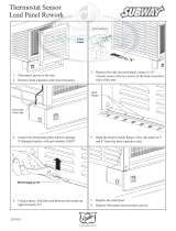
THERMOSTAT REPLACEMENT: Oven
Inside the oven cavity remove the retaining clips holding the thermostat-sensing bulb in place. Deed the
bulb through the oven wall into the control panel area. Remove the wires attached to the thermostat
terminals. Remember the terminal each wire was on and attach the wires to the same terminal on the new
thermostat. Remove the screws holding the old thermostat to the front of the control panel. Discard old
thermostat. Mount the new thermostat to the control panel, carefully feed the sensing bulb through the
oven wall and reattach the sensing bulb to the oven side using the retaining clips removed earlier. Close
control compartment. Restore power to the oven.
THERMOSTAT REPLACEMENT: Range
Raise the griddle or hot top plate up to allow access to the bottom of the plate. The thermostat is the
silver tube clamped to the bottom of the griddle or hot top through the slot in the element holder. Remove
bracket holding the sensing bulb to the bottom of the plate. Fish the old tube and bulb through the
wireway out of the front of the range. Install the new thermostat by reversing these steps.
CAUTION:
After installing the new thermostat be positive the silver tube is not near any exposed
terminals. If the thermostat tube touches any live terminals it will be destroyed and have to be replaced
again.
ELEMENT REPLACEMENT: Oven
Remove sheet metal screws holding control panel to range.
Remove wires from affected oven element. Mark wires for proper replacement.
Bend tab on clips holding element to oven top or bottom, to allow element to be pulled out of bushing
through oven wall.
Reverse procedure for installation.
ELEMENT REPLACEMENT: Hot top or griddle
Remove grease drawers from under griddle or hot top.
Remove upper control panel, leaving controls attached to panel.
Remove terminal block cover, located behind louvered door to the right of the upper controls.
Remove the wires going to griddle or hot top elements from thermostats, if present. Push wires through
wire tubes to gain slack wire under griddle or hot top.
Uncoil thermostat capillary tubes and push through holes in rear of control box to gain slack under grill if
present.
Using a 2” x 4”, or similar lever, pry front edge of griddle of hot top u. block front edge of griddle at
approximately eight inches high.

12
Remove the two (2) 10 x 1/2” sheet metal screws holding the capillary tube clamp, if present, to the
bottom of the affected element pan.
Remove four (4) nuts attaching the wires to the elements. Mark the wires for proper replacement.
Remove five (5) 5/16 hex nut holding the element pan to the griddle plate and lower the element pan until
it clears the attaching stud.
Remove the element pan from the range and remove and discard affected element.
Clean all slag and debris from element pan. Make sure there are no sharp objects remaining at the point
where the old element shorted.
Reverse procedure for Installation.
CAUTION:
Make sure element pan is clamped tightly to the bottom of griddle plate or hot top and
that thermostat capillary tube is secure in capillary clamp and tight against bottom of griddle plate, if
present.
PREPARATION FOR RESHIPMENT
Refer to Installation Instructions. Follow these instructions in reverse order. When range is disassembled
coat the exterior and surfaces with protective oil for preservation during storage. Then crate each major
piece in a wooden box suitable for forklift access. Insure that adequate cushioning is provided on all
sides to prevent in-transit damage.

13

14

15
PARTS LIST
DESCRIPTION PART NO.
Element To
p
Plate 208V O/S 2000 Watts 11010-09
Element To
p
Plate 208V I/S 3000 Watts 11010-10
Element To
p
Plate 240V O/S 2000 Watts 11010-21
Element To
p
Plate 240V I/S 3000 Watts 11010-22
Element To
p
Plate 480V O/S 2000 Watts 11010-23
Element To
p
Plate 480V I/S 3000 Watts 11010-24
Hot Plate Cast Ass
y
with Elements 208V 5000 Watts 11010-34
Hot Plate Cast Ass
y
with Elements 240V 5000 Watts 11010-35
Hot Plate Cast Ass
y
with Elements 480V 5000 Watts 11010-36
Element 36 Oven 240 Volt O/S 1800 Watts 11050-25
Element 36 Oven 240 Volt I/S 1200 Watts 11050-26
Element 36 Oven 480 Volt O/S 1800 Watts 11050-29
Element 36 Oven 480 Volt I/S 1200 Watts 11050-30
Element 36 Oven 208 Volt O/S 1800 Watts 11050-31
Element 36 Oven 208 Volt I/S 1200 Watts 11050-32
Element French Plate 208 Volt 2600 Watts 11120-12
Element French Plate 240 Volt 2600 Watts 11120-13
Element French Plate 480 Volt 2600 Watts 11120-14
Switch Rotatin
g
3 Heat 30304-06
Switch Rotatin
g
6 Heat + Off 30304-09
Thermostat 550°F Oven
30402-07
Thermostat 450°F Griddle
30402-08
Thermostat 850°F Hot To
p
30402-23
Terminal Block 3 Pole Lar
g
e 30500-07
Timer Mechanical Lon
g
Rin
g
30801-01
Pilot Li
g
ht 208/240 Volt 6” Lead Black Bod
y
31601-01
Pilot Li
g
ht 480 Volt 6” Lead Black Bod
y
31601-02
Circuit Breaker 208/240 Volt 1-Pole 31800-01
Circuit Breaker 480 Volt 3-Pole 31800-04
Rack Oven CLS Onl
y
50200-72
Handle Channel Marine 50300-14
Element Pan Assembl
y
with Snout 50300-20
Grab Bar Assembl
y
36” Lon
g
CLS 50300-32
Handle Assembl
y
Marine 50300-38
Grab Bar Assembl
y
36” Lon
g
50300-44
Pan Latch Assembl
y
Marine 50300-63
French Plate Frame Assembl
y
50300-82
Element Cli
p
Lon
g
50301-09
Element Cli
p
Short 50301-10
Element Bushin
g
Metal 50301-11
Rotar
y
Latch 50307-50
Ran
g
e Plate Ass
y
1/2” x 1 foot 50401-01
Ran
g
e Plate Ass
y
1/2” x 2 foot 50401-02
Ran
g
e Plate Ass
y
1/2” x 3 foot 50401-03
Tension Disc Oven Door 50800-07
Shi
p
Rail 13” 50900-01
Shi
p
Rail 24” 50900-02
Shi
p
Rail 35 3/8” 50900-04
Shi
p
Rail Hooked 11 3/8” 50901-01

16
DESCRIPTION PART NO.
Shi
p
Rail Hooked 32 1/4” 50901-04
S
p
rin
g
Left Side 7 1/2” Lon
g
– Oven Door 51001-01
S
p
rin
g
Ri
g
ht Side 7 1/2” Lon
g
– Oven Door 51001-02
Shi
p
Rail Socket Front 60102-981
Shi
p
Rail Socket Rear 60102-982
Handle Assembl
y
Oven Door 70603-05
Knob Manual Timer 70701-09
Knob 3 Heat Switch 70701-10
Knob Thermostat 550°F Oven
70701-15
Knob Thermostat 450°F Griddle
70701-16
Knob Dam
p
er Black 70701-25
Knob Thermostat 850°F Hot To
p
70701-35
Knob 6 Heat Switch 70701-41
/