
FormNo.3406-730RevA
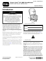
PowerClear
®
721QZESnowthrower
ModelNo.38744—SerialNo.400010798andUp
Operator'sManual
Introduction
WARNING
CALIFORNIA
Proposition65Warning
Thisproductcontainsachemicalorchemicals
knowntotheStateofCaliforniatocausecancer,
birthdefects,orreproductiveharm.
Theengineexhaustfromthisproduct
containschemicalsknowntotheStateof
Californiatocausecancer,birthdefects,
orotherreproductiveharm.
Thismachineisintendedtobeusedbyresidential
homeownersorprofessional,hiredoperators.Itis
designedprimarilyforremovingsnowfrompaved
surfaces,suchasdrivewaysandsidewalks,andother
surfacesfortrafconresidentialorcommercial
properties.Itisnotdesignedforremovingmaterials
otherthansnow,norisitdesignedforclearingoffgravel
surfaces.
Readthisinformationcarefullytolearnhowtooperateand
maintainyourmachineproperlyandtoavoidinjuryand
machinedamage.Youareresponsibleforoperatingthe
machineproperlyandsafely.
YoumaycontactTorodirectlyatwww .Toro.comformachine
andaccessoryinformation,helpndingadealer,ortoregister
yourmachine.
Wheneveryouneedservice,genuineToroparts,oradditional
information,contactanAuthorizedServiceDealerorToro
CustomerServiceandhavethemodelandserialnumbersof
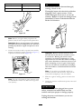
yourmachineready.Figure1identiesthelocationofthe
modelandserialnumbersonthemachine.Writethenumbers
inthespaceprovided.
Figure1
1.Modelandserialnumberlocation
ModelNo.
SerialNo.
Thismanualidentiespotentialhazardsandhassafety
messagesidentiedbythesafety-alertsymbol(Figure2),
whichsignalsahazardthatmaycauseseriousinjuryordeath
ifyoudonotfollowtherecommendedprecautions.
Figure2
1.Safety-alertsymbol
Thismanualuses2wordstohighlightinformation.
Importantcallsattentiontospecialmechanicalinformation
andNoteemphasizesgeneralinformationworthyofspecial
attention.
Important:Ifyouareusingthismachineabove1500m
(5,000ft)foracontinuousperiod,ensurethattheHigh
AltitudeKithasbeeninstalledsothattheenginemeets
CARB/EPAemissionregulations.TheHighAltitude
Kitincreasesengineperformancewhilepreventing
spark-plugfouling,hardstarting,andincreased
emissions.Onceyouhaveinstalledthekit,attach
thehigh-altitudelabelnexttotheserialdecalonthe
machine.ContactanyAuthorizedToroServiceDealer
toobtaintheproperHighAltitudeKitandhigh-altitude
labelforyourmachine.Tolocateadealerconvenientto
©2016—TheToro®Company
8111LyndaleAvenueSouth
Bloomington,MN55420
Registeratwww.Toro.com.
OriginalInstructions(EN)
PrintedintheUSA
AllRightsReserved
*3406-730*A

you,accessourwebsiteatwww.Toro.comorcontactour
ToroCustomerCareDepartmentatthenumber(s)listed
inyourEmissionControlWarrantyStatement.
Removethekitfromtheengineandrestoretheengine
toitsoriginalfactorycongurationwhenrunningthe
engineunder1500m(5,000ft).Donotoperateanengine
thathasbeenconvertedforhigh-altitudeuseatlower
altitudes;otherwise,youcouldoverheatanddamage
theengine.
Ifyouareunsurewhetherornotyourmachinehasbeen
convertedforhigh-altitudeuse,lookforthefollowing
label(Figure3).
Figure3
Contents
Introduction..................................................................1
Safety...........................................................................3
SafetyandInstructionalDecals.................................3
Setup............................................................................4
1UnfoldingtheHandle............................................4
2InstallingtheDischargeChute................................4
3FillingtheEnginewithOil......................................5
4AdjustingtheControlCable...................................5
ProductOverview..........................................................6
Operation.....................................................................7
BeforeOperation.......................................................7
Safety.....................................................................7
FillingtheFuelTank................................................7
CheckingtheEngine-OilLevel..................................7
DuringOperation......................................................8
Safety.....................................................................8
StartingtheEngine..................................................8
EngagingtheRotorBlades.......................................10
DisengagingtheRotorBlades..................................10
ShuttingOfftheEngine..........................................10
AdjustingtheDischargeChuteandChute
Deector...........................................................10
ClearingaCloggedDischargeChute.........................11
OperatingTips......................................................11
AfterOperation........................................................11
Safety....................................................................11
PreventingFreeze-upafterUse.................................11
Maintenance.................................................................12
RecommendedMaintenanceSchedule(s)......................12
MaintenanceSafety.................................................12
AdjustingtheControlCable.....................................12
InspectingtheRotorBlades.....................................13
ChangingtheEngineOil.........................................14
ServicingtheSparkPlug..........................................15
ReplacingtheDriveBelt..........................................16
AdjustingtheQuickShoot™Control........................17
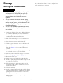
Storage........................................................................19
StoringtheSnowthrower.........................................19
2

Safety
•ReadandunderstandthecontentsofthisOperator’sManual
beforeyoustarttheengine.Ensurethateveryoneusing
thisproductknowshowtouseitandunderstandsthe
warnings.
•Donotputyourhandsorfeetnearmovingcomponents
onthemachine.
•Donotoperatethemachinewithoutallguardsandother
safetyprotectivedevicesinplaceandworkingonthe
machine.
•Keepclearofanydischargeopening.Keepbystandersa
safedistanceawayfromthemachine.
•Keepchildrenoutoftheoperatingarea.Neverallow
childrentooperatethemachine.
•Shutofftheenginebeforeunclogging,servicing,or
fuelingthemachine.
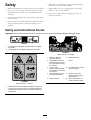
SafetyandInstructionalDecals
Important:Safetyandinstructiondecalsarelocatednearareasofpotentialdanger.Replacedamageddecals.
94-2577
1.Toengagetherotorblades,holdthecontrolbaragainst
thehandle.
2.Todisengagetherotorblades,releasethecontrolbar.
115-5698
OrderPartNo.117-9121
1.Cuttingdismembermenthazards,impellerandauger—do
notplaceyourhandinthechute;removetheignitionkey
andreadtheinstructionsbeforeservicingorperforming
maintenance.
117-9103
OrderPartNo.117-6046
1.Warning—readthe
Operator'sManual.
6.Engineswitchoff
2.Cutting/dismemberment
hazard,impeller—shutoff
theenginebeforeleaving
themachine.
7.Primer
3.Thrownobject
hazard—keepbystanders
asafedistanceawayfrom
themachine.
8.Pushtheprimer3timesto
primetheengine.
4.Fuelspillhazard—donot
tipmachinebackward.
9.ReadtheOperator's
Manualbeforechecking
engine-oillevel.
5.Engineswitchon10.Plugthemachineinto
powertheelectricstarter.
3

Setup
LooseParts
Usethechartbelowtoverifythatallpartshavebeenshipped.
ProcedureDescription
Qty.
Use
1
Nopartsrequired
–
Unfoldthehandle.
Screw
3
Chuteassembly
1
2
Discharge-chutehandle1
Installthedischargechute.
1
UnfoldingtheHandle
NoPartsRequired
Procedure
1.Loosenthehandleknobs,pullouttheU-shapedhandle
locksuntilyoucanmovethehandlefreely,androtate
thehandletotheoperatingposition(Figure4).
Figure4
1.U-shapedhandlelock(2)
2.Handleknobs
2.InserttheendoftheU-shapedhandlelockintothe
openholeinthehandleandtightenthehandleknobs
untiltheyaresnug(Figure5).
Note:Thehandleknobscontainnylocnutsthat
requiremorepressuretotightenfullytopreventthe
handlefromcominglooseduringoperation.
Figure5
Important:Ensurethatyoudonotpinchorkink
thecontrolcable(Figure6).
Figure6
1.Controlcable
4

2
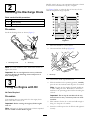
InstallingtheDischargeChute
Partsneededforthisprocedure:
3
Screw
1
Chuteassembly
1Discharge-chutehandle
Procedure
Installthedischargechuteasshown(Figure7).
Figure7
1.Dischargechute
2.Screw(3)
Note:Foreasierinstallation,useasmallratchetwrenchto
tightenthescrews.
Important:Donotovertightenthescrews;otherwise
youmaydamagethedischargechuteandpreventit
fromturningfreely.
3
FillingtheEnginewithOil
NoPartsRequired
Procedure
Yourmachinedoesnotcomewithoilintheengine,butit
doescomewithabottleofoil.
Important:Beforestartingtheengine,lltheengine
withoil.
Note:Thebottleofoilmaycontainmoreoilthanisrequired.
Donotoverllorunderlltheengine.
Maxll:.0.60L(20oz),type:automotivedetergentoilwith
anAPIserviceclassicationofSJ,SL,orhigher.
UseFigure8belowtoselectthebestoilviscosityforthe
outdoortemperaturerangeexpected.
Figure8
1.Movethemachinetoalevelsurface.
2.Cleanaroundtheoil-llcap(Figure9).
Figure9
1.Oil-llcap
3.Unscrewtheoil-llcapandremoveit.
4.Withthemachineintheoperatingposition,carefully
pouroilintothecrankcaseuntilthepointofoverow .
Note:Youmaytipthemachineforward(handleup)
tomakeaddingoileasier.Remembertoreturnthe
machinetotheoperatingpositionbeforecheckingthe
oillevel.
Important:Donottipthemachinealltheway
forwardontoitsnose,orfuelmayleakoutofthe
machine.
5.Wait3minutesfortheoiltosettleandaddenoughto
bringittothepointofoverow.
6.Screwtheoil-llcapintotheoil-llholeandtightenit
securely.
5

4
AdjustingtheControlCable
NoPartsRequired
Procedure
RefertoAdjustingtheControlCable(page13).
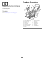
ProductOverview
Figure10
1.Chute-deectortrigger
8.Electric-startbutton
2.Dischargechute9.Ignitionkey
3.Fuel-tankcap
10.Chokelever
4.Controlbar11.Oil-drainplug
5.QuickShoot™control12.Oil-llcap
6.Recoil-starthandle
13.Chutedeector
7.Primer
6

Operation
BeforeOperation
Safety
•Useextensioncordsandreceptaclesasspeciedby
themanufacturerforallmachineswithelectric-starting
motors.
•Donotoperatethemachinewithoutwearingadequate
wintergarments.Avoidloosettingclothingthatcanget
caughtinmovingparts.Wearslipresistantfootwearthat
willimprovefootingonslipperysurfaces.
•Alwayseyeprotectionduringoperationorwhile
performinganadjustmentorrepairtoprotectyoureyes
fromforeignobjectsthatthemachinemaythrow .
•Thoroughlyinspecttheareawhereyouwillusethe
machineandremovealldoormats,sleds,boards,wires,
andotherforeignobjects.
•Ifashield,safetydevice,ordecalisdamaged,illegible,or
lost,repairorreplaceitbeforebeginningoperation.Also,
tightenanyloosefasteners.
FillingtheFuelTank
•Forbestresults,useonlyclean,fresh(lessthan30days
old),unleadedgasolinewithanoctaneratingof87or
higher((R+M)/2ratingmethod).
•Ethanol:Gasolinewithupto10%ethanol(gasohol)
or15%MTBE(methyltertiarybutylether)byvolume
isacceptable.EthanolandMTBEarenotthesame.
Gasolinewith15%ethanol(E15)byvolumeisnot
approvedforuse.Neverusegasolinethatcontainsmore
than10%ethanolbyvolume,suchasE15(contains15%
ethanol),E20(contains20%ethanol),orE85(contains
85%ethanol).Usingunapprovedgasolinemaycause
performanceproblemsand/orenginedamagewhichmay
notbecoveredunderwarranty.
•Donotusegasolinecontainingmethanol.
•Donotstorefueleitherinthefueltankorfuelcontainers
overthewinterunlessyouuseafuelstabilizer.
•Donotaddoiltogasoline.
Figure11
1.6mm(1/4inch)
Note:Forbestresults,purchaseonlythequantityofgasoline
thatyouexpecttousein30days.Otherwise,youmayadd
fuelstabilizertonewlypurchasedgasolinetokeepitfreshfor
upto6months.
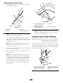
CheckingtheEngine-OilLevel
ServiceInterval:Beforeeachuseordaily—Checkthe
engine-oillevelandaddoilifnecessary.
1.Movethemachinetoalevelsurface.
2.Cleanaroundtheoil-llcap(Figure12).
Figure12
1.Oil-llcap
3.Unscrewtheoil-llcapandremoveit.
4.Iftheoillevelislow,keepthemachineintheoperating
positionandcarefullypouroilintothecrankcase
untilthepointofoverow.Wait3minutesfortheoil
tosettleandaddenoughtobringittothepointof
overow .(Max.ll:0.60L(20oz),type:SAE30
detergentoilwithanAPIserviceclassicationofSJ,
SL,orhigher.)
7

Note:Youmaytipthemachineforward(handleup)
tomakeaddingoileasier.Remembertoreturnthe
machinetotheoperatingpositionbeforecheckingthe
oillevel.
Important:Donottipthemachinealltheway
forwardontoitsnose,orfuelmayleakoutofthe
machine.
5.Screwtheoil-llcapintotheoil-llholeandtighten
itsecurelybyhand.
DuringOperation
Safety
•Rotatingaugerbladescaninjurengersorhands.
Staybehindthehandlesandawayfromthedischarge
openingwhileoperatingthemachine.Keepyourface,
hands,feet,andanyotherpartofyourbodyor
clothingawayfrommovingorrotatingparts.
•Neverdirectthedischargetowardpeopleorareaswhere
propertydamagecanoccur.
•Exercisecautiontoavoidslippingorfalling.Alwaysbe
sureofyourfooting,andkeeparmholdonthehandles.
Walk;neverrun.
•Exerciseextremecautionwhenoperatingonslopes.
•Neveroperatethemachinewithoutgoodvisibilityor
light.
•Lookbehindandusecarewhenbackingupwiththe
machine.
•Whennotactivelyclearingsnow ,disengagepowertothe
rotorblades.
•Useextensioncordsandreceptaclesasspeciedby
themanufacturerforallmachineswithelectric-starting
motors.
•Donotattempttoclearsnowfromagravelorcrushed
rocksurface.Thisproductisintendedforuseonlyon
pavedsurfaces.
•Donotusethemachineonaroof.
•Neverattempttomakeanyadjustmentswhiletheengine
isrunning(exceptwhenspecicallyrecommendedby
manufacturer).
•Stayalertforhiddenhazardsortrafc.
•Afterstrikingaforeignobject,shutofftheengine,
removetheignitionkey,thoroughlyinspectthemachine
foranydamage,andrepairthedamagebeforestarting
andoperatingthemachine.
•Ifthemachineshouldstarttovibrateabnormally,shutoff
theengineandcheckimmediatelyforthecause.
•Donotruntheengineindoors,exceptwhenstarting
theengineandfortransportingthemachineinorout
ofthebuilding.Opentheoutsidedoors;exhaustfumes
aredangerous.
•Donotoverloadthemachinecapacitybyattemptingto
clearsnowattoofastarate.
•Nevertouchahotengineormufer.
•Thoroughlyinspecttheelectricalcordbeforeplugging
itintoapowersource.Ifthecordisdamaged,donot
useittostartthemachine.Replacethedamagedcord
immediately.Unplugthepowercordwheneveryouare
notstartingthemachine.
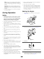
StartingtheEngine
1.TurntheignitionkeyclockwisetotheONposition
(Figure13).
Figure13
2.Pulloutthechokelever(Figure14andFigure15).
Figure14
1.Chokelever
Figure15
1.Symbolsonthechokeleverindicatingtopulloutthechoke
levertoactivatethechoke
3.Firmlypushintheprimerwithyourthumbasindicated
bythechartbelow,holdingintheprimerforasecond
beforereleasingiteachtime(Figure16).
8

Numberofprimes
Temperature
3
0°F(-18°C)orabove
6
Below0°F(-18°C)
Figure16
Note:Removeyourglovewhenyoupushinthe
primersothataircannotescapefromtheprimerhole.
Important:Donotusetheprimerorthechokeif
theenginehasbeenrunningandishot.Excessive
primingmayoodtheengineandpreventitfrom
starting.
4.Connectanextensioncordtoapowersourceandthe
machine,andpushtheelectric-startbutton(Figure17),
orpulltherecoil-starthandle(Figure18).
Figure17
Note:UseonlyaUL-listed,16-gaugeextensioncord
recommendedforoutdoorusethatisnotlongerthan
15m(50feet).
WARNING
Theelectricalcordcanbecomedamaged,
causingashockorre.
Thoroughlyinspecttheelectricalcordbefore
pluggingitintoapowersource.Ifthe
cordisdamaged,donotuseittostartthe
machine.Replaceorrepairthedamagedcord
immediately.ContactanAuthorizedService
Dealerforassistance.
Figure18
Important:Runtheelectricstarternomore
than10timesatintervalsof5secondson,then
5secondsoff.Runningtheelectricstarter
extensivelycanoverheatanddamageit.Ifthe
enginedoesnotstartafterthisseriesofattempts,
waitatleast40minutestoallowthestartertocool
beforeattemptingtostartitagain.Iftheengine
doesnotstartafterthesecondseriesofattempts,
takethemachinetoanAuthorizedServiceDealer
forservice.
Note:Ifyoupulltherecoilhandleandfeelno
resistance,thestartermaybefrozen.Thawoutthe
starterbeforeattemptingtostartthemachine.
5.Whiletheengineisrunning,pushinthechokelever
slowly.
6.Unplugtheextensioncordfromthepowersourceand
themachine.
CAUTION
Ifyouleavethemachinepluggedintoapower
source,someonecaninadvertentlystartthe
machineandinjurepeopleordamageproperty.
Unplugthepowercordwheneveryouarenot
startingthemachine.
9

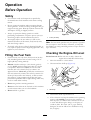
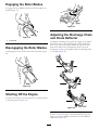
EngagingtheRotorBlades
Toengagetherotorblades,holdthecontrolbaragainstthe
handle(Figure19).
Figure19
1.Controlbar
DisengagingtheRotorBlades
Todisengagetherotorblades,releasethecontrolbar(Figure
20).
Figure20
ShuttingOfftheEngine
Toshutofftheengine,turntheignitionkeycounterclockwise
totheOFFposition(Figure21).
Figure21
AdjustingtheDischargeChute
andChuteDeector
Toadjustthedischargechute,pressthetriggeroftheQuick
Shoot™controlontherighthandsideofthehandleand
moveitupordownalongthehandle.Movingthecontrol
downthehandlerotatesthedischargechutetotheleft;
movingthecontrolupthehandlerotatesthedischargechute
totheright(Figure22).
Figure22
Toraiseorlowertheangleofthechutedeector,pressthe
triggeronthechutedeectorandmovethechutedeector
upordown(Figure23).
10

Figure23
1.Chute-deectortrigger2.Chutedeector
ClearingaCloggedDischarge
Chute
WARNING
Handcontactwiththerotatingrotorbladesinside
thedischargechuteisthemostcommoncauseof
injuryassociatedwithmachines.Neveruseyour
handtocleanoutthedischargechute.
Toclearthechute:
•Shutofftheengine!
•Wait10secondstoensurethattherotorbladeshave
stoppedrotating.
•Alwaysuseacleanouttool,notyourhands.
OperatingTips
WARNING
Therotorbladescanthrowstones,toys,andother
foreignobjectsandcauseseriouspersonalinjuryto
theoperatorortobystanders.
•Keeptheareatobeclearedfreeofallobjects
thattherotorbladescouldpickupandthrow.
•Keepallchildrenandpetsawayfromthearea
ofoperation.
•Removethesnowassoonaspossibleafteritfalls.
•Ifthemachinedoesnotpropelitselfforwardonslippery
surfacesorinheavysnow ,pushforwardonthehandle,
butallowthemachinetoworkatitsownpace.
•Overlapeachswathtoensurecompletesnowremoval.
•Dischargethesnowdownwindwheneverpossible.
AfterOperation
Safety
•Neverstorethemachinewithfuelinthefueltankinsidea
buildingwhereignitionsourcesarepresent,suchashot
waterheaters,spaceheaters,orclothesdryers.Allowthe
enginetocoolbeforestoringinanyenclosure.
•Whenstoringthemachineformorethan30days,referto
Storage(page19)forimportantdetails.
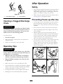
PreventingFreeze-upafterUse
•Lettheenginerunforafewminutestopreventmoving
partsfromfreezing.Shutofftheengine,waitforall
movingpartstostop,andremoveiceandsnowfromthe
machine.
•Cleanoffanysnowandicefromthebaseofthechute.
•Rotatethedischargechuteleftandrighttofreeitfrom
anyicebuildup.
•WiththeignitionkeyintheOFFposition,pullthe
recoil-starthandleseveraltimesorconnecttheelectrical
cordtoapowersourceandthemachineandpushthe
electric-startbuttononcetopreventtherecoilstarter
and/ortheelectricstarterfromfreezingup.
•Insnowyandcoldconditions,somecontrolsandmoving
partsmayfreeze.Donotuseexcessiveforcewhen
tryingtooperatefrozencontrols.Ifyouhavedifculty
operatinganycontrolorpart,starttheengineandletit
runforafewminutes.
1
2
G016654
3
4
Figure24
11

Maintenance
Note:Determinetheleftandrightsidesofthemachinefromthenormaloperatingposition.
RecommendedMaintenanceSchedule(s)
MaintenanceService
Interval
MaintenanceProcedure
Afterthersthour
•Checkthecontrolcableandadjustitifnecessary.
•Checkforloosefastenersandtightenthemifnecessary.
Aftertherst2hours
•Changetheengineoil.
Beforeeachuseordaily
•Checktheengine-oillevelandaddoilifnecessary.
Yearly
•Checkthecontrolcableandadjustitifnecessary.
•InspecttherotorbladesandhaveanAuthorizedServiceDealerreplacetherotor
bladesandscraperifnecessary.
•Changetheengineoil.
•Checkthesparkplugandreplaceitifnecessary.
•Checkforloosefastenersandtightenthemifnecessary.
•HaveanAuthorizedServiceDealerinspectthedrivebeltandreplaceitifnecessary.
Yearlyorbeforestorage
•Preparethemachineforstorage.
MaintenanceSafety
Readthefollowingsafetyprecautionsbeforeperformingany
maintenanceonthemachine:
•Beforeperforminganymaintenance,service,or
adjustment,shutofftheengineandremovethekey.If
majorrepairsareeverneeded,contactanAuthorized
ServiceDealer.
•Checkallfastenersatfrequentintervalsforproper
tightnesstobesurethemachineisinsafeworking
condition.
•Maintainorreplacesafetyandinstructionlabels,as
necessary.
•Donotchangethegovernorsettingsontheengine.
•PurchaseonlygenuineTororeplacementpartsand
accessories.
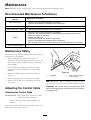
AdjustingtheControlCable
CheckingtheControlCable
ServiceInterval:Afterthersthour—Checkthecontrol
cableandadjustitifnecessary.
Yearly—Checkthecontrolcableandadjustitif
necessary.
Movethecontrolbarbacktowardthehandletoremovethe
slackinthecontrolcable(Figure25).
Figure25
1.Controlbar2.2mmto3mm(1/16inch
to1/8inch)gap
Note:Ensurethata2mmto3mm(1/16inchto1/8inch)
gapexistsbetweenthecontrolbarandthehandle(Figure25).
Important:Thecontrolcablemustcontainsomeslack
whenyoudisengagethecontrolbarfortherotorblades
tostopproperly.
12

AdjustingtheControlCable
1.Slideupthespringcoverandunhookthespringfrom
theadjusterlink(Figure26).
Figure26
1.Adjusterlink
3.Springcover
2.Z-tting
4.Unhookthespringhere.
Note:Youcanpulluptheadjusterlinkandcableto
makeunhookingthespringeasier.
2.MovetheZ-ttingtoahigherorlowerholeonthe
adjusterlinkasneededtoobtainthe1/16inchto1/8
inch(2mmto3mm)gapbetweenthecontrolbarand
thehandle(Figure25).
Note:MovingtheZ-ttinghigherdecreasesthegap
betweenthecontrolbarandthehandle;movingit
lowerincreasesthegap.
3.Hookthespringtotheadjusterlinkandslidethespring
coverovertheadjusterlink.
4.Checktheadjustment;refertoCheckingtheControl
Cable(page12).
Note:Afterextendeduse,thedrivebeltmaywear
andloseitsproperbelttension.Ifthedrivebeltslips
(continuouslysqueals)underaheavyload,disconnect
thespringfromtheadjustorlinkandmovetheupper
endofthespringtotheholethatisfurtherfrom
thepivotpointinthecontrolbar(Figure27).Then
connectthespringtotheadjustorlinkandadjustthe
controlcable.
Figure27
1.Removetheupperendof
springfromthishole.
3.Pivotpoint
2.Inserttheupperendof
springintothishole.
4.Upperendofspring
Note:Thebeltmayslip(squeal)inwetconditions;
todryoutthedrivesystem,starttherotorandrunit
withoutaloadfor30seconds.
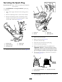
InspectingtheRotorBlades
ServiceInterval:Yearly—Inspecttherotorbladesandhave
anAuthorizedServiceDealerreplacethe
rotorbladesandscraperifnecessary.
Beforeeachsession,inspecttherotorbladesforwear.When
arotorbladeedgehasworndowntothewear-indicatorhole,
haveanAuthorizedServiceDealerreplacetherotorblades
andthescraper(Figure28).
Figure28
1.Thewear-indicatorholeis
intact;youdonotneedto
replacetherotorblades.
2.Thewear-indicatorholeis
exposed;replacetherotor
blades.
13

ChangingtheEngineOil
ServiceInterval:Aftertherst2hours
Yearly
Runtheengineafewminutesbeforechangingtheoiltowarm
it.Warmoilowsbetterandcarriesmorecontaminants.
1.Siphonthefuelfromthefueltankintoanapproved
fuelcontainer,orruntheengineuntilitshutsoff.
2.Movethemachinetoalevelsurface.
3.Placeanoil-drainpanundertheoil-drainplug,remove
theplug,andtipthemachinebackwardanddrainthe
usedoilinthepanFigure29).
Figure29
4.Afterdrainingtheusedoil,returnthemachinetothe
operatingposition.
5.Installtheoil-drainplugandtightenitsecurely.
6.Cleanaroundtheoil-llcap(Figure30).
Figure30
1.Oil-llcap
7.Unscrewtheoil-llcapandremoveit(Figure30).
8.Withthemachineintheoperatingposition,carefully
pouroilintotheoil-llholetothepointofoverow
(Figure32).
Note:Youmaytipthemachineforward(handleup)
tomakeaddingoileasier.Remembertoreturnthe
machinetotheoperatingpositionbeforecheckingthe
oillevel.
Important:Donottipthemachinealltheway
forwardontoitsnose,orfuelmayleakoutofthe
machine.
Maxll:0.60L(20oz),type:automotivedetergentoil
withanAPIserviceclassicationofSJ,SL,orhigher.
UseFigure31belowtoselectthebestoilviscosityfor
theoutdoortemperaturerangeexpected.
Figure31
Figure32
9.Wait3minutesfortheoiltosettleandaddenoughto
bringittothepointofoverow.
10.Screwtheoil-llcapintotheoil-llhole,andtighten
itsecurelybyhand.
11.Wipeupanyspilledoil.
12.Disposeoftheusedoilproperlyatalocalrecycling
center.
14

ServicingtheSparkPlug
ServiceInterval:Yearly—Checkthesparkplugandreplace
itifnecessary.
UseaNGKBPR6ESorChampionRN9YCsparkplug
orequivalent.
1.Shutofftheengineandwaitforallmovingpartsto
stop.
2.Rotatethedischargechutesothatitfacesforward.
3.Removethedischargechute,thedischargechute
handle,andthechutesealbyremovingthe3large
screwsand1smallscrew(Figure33).
Figure33
1.Fuel-tankcap
4.Smallscrew
2.Largescrews(3)5.Chuteseal
3.Dischargechute
4.Removethe4screwsthatsecuretheshroud(Figure34).
Figure34
1.Screw(4)3.Sparkplug
2.Shroud4.Spark-plugwire
5.Removethefuel-tankcap.
6.Removetheshroud(Figure34).
7.Installthefuel-tankcap.
8.Disconnectthewirefromthesparkplug.
9.Cleanaroundthesparkplug.
10.Removethesparkplugfromthecylinderhead.
Important:Replaceacracked,fouled,ordirty
sparkplug.Donotcleantheelectrodesbecause
gritenteringthecylindercandamagetheengine.
11.Setthegapontheplugto0.030inch(0.76mm)as
showninFigure35.
Figure35
1.Center-electrodeinsulator3.Airgap(nottoscale)
2.Sideelectrode
12.Installthesparkplugandtorqueitto20to22ft-lb
(27to30N-m).
15

13.Connectthewiretothesparkplug.
Note:Ensurethatthebreathertubeisroutedabove
thespark-plugwireasshowninFigure36.
Figure36
1.Breathertube
2.Carburetordrainbolt
14.Removethefuel-tankcap.
15.Installtheshroudwiththescrewsthatyouremoved
instep4.
Note:Ensurethattheupperandlowershroudst
togetherinthesidegrooves.
16.Installthefuel-tankcap.
17.Installthechuteseal,thedischargechute,andthe
dischargechutehandleontothemachineusingthe
hardwarethatyouremovedinstep3.
Note:Thesmallscrewgoesthroughthesmallhole
inthechutesealatthefrontofthedischarge-chute
opening.
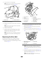
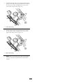
ReplacingtheDriveBelt
Ifthedrivebeltbecomesworn,oil-soaked,excessively
cracked,frayed,orotherwisedamaged,replacethebelt.
1.Removethedrivebeltcoverbyremovingthe3boltsas
showninFigure37.
Figure37
1.Drive-beltcover6.Drivebelt
2.Bolt(3)7.Rotorshaft
3.Rotor-pulleybolt
8.Brakespring(unhookfrom
idlerarmhere)
4.Curvedwasher
9.Idlerpulley
5.Rotorpulley10.Enginepulley
2.Unhookthebrakespringfromtheidlerarmtorelease
thebelttension(Figure37).
3.Removethescrewandcurvedwasherthatholdsthe
rotorpulley(Figure37).
4.Removetherotorpulleyandthedrivebelt(Figure37).
5.Installthenewdrivebelt,routingitasshownin(Figure
38).
Figure38
1.Brakespring(installon
idlerarmhere)
3.Enginepulley
2.Idlerpulley4.Rotorpulley
Note:Routethenewdrivebeltrstaroundtheengine
pulley,thentheidlerpulley,andnallyaroundthe
looserotorpulleypositionedjustabovetherotorshaft
(Figure37).
6.Installtherotorpulleyontotherotorshaft(Figure37).
7.Installthecurvedwasherandtherotor-pulleyboltand
tightenthemsecurely(Figure37).
Note:Theconcavesideofthecurvedwashergoes
againsttheoutsideofthepulley.
16

8.Installthebrakespringontotheidlerarm(Figure38).
9.Installthedrivebeltcoverwiththeboltsthatyou
removedinstep1.
Note:Ensurethatthedrivebeltisproperlyadjusted
andoperating;refertoCheckingtheControlCable
(page12)andAdjustingtheControlCable(page13).
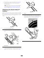
AdjustingtheQuickShoot™
Control
Ifthereismorethan13mm(1/2inch)ofslackintheQuick
Shootcable(Figure39)orthedischargechutedoesnotrotate
leftandrightinequalangles,adjusttheQuickShootcontrol
cables.
Figure39
1.13mm(1/2inch)maximumslack
1.Loosenthe2QuickShootcontrol-cableclamps(Figure
40).
Figure40
1.Cableclamps
2.PositiontheQuickShootcontrolbetweenthe2arrows
locatedontherightsideoftheupperhandle(Figure
41).
Figure41
1.Arrows
3.Rotatethedischargechutesothatitfacesstraight
aheadandthearrowonthebackofthedischargechute
alignswiththearrowontheshroud(Figure42).
Figure42
17

4.Holdthedischargechuteinthestraight-aheadposition,
pullthelowercablecasingdownwarduntilyouremove
theslackinthecable,andtightenthescrewonthe
lowercableclampsecurely(Figure43).
Figure43
1.Lowercablecasing
5.Pulltheuppercablecasingforwarduntilyouremove
theslackinthecable,andtightenthescrewonthe
uppercableclampsecurely(Figure44).
Figure44
1.Uppercablecasing
Note:Donotover-tensionthecables.Ifthecables
areover-tensioned,theQuickShootwillbehardto
operate.
18

Storage
StoringtheSnowthrower
WARNING
•Gasolinefumesarehighlyammable,explosive,
anddangerousifinhaled.Ifyoustorethe
machineinanareawithanopename,the
gasolinefumesmayigniteandcausean
explosion.
•Donotstorethemachineinahouse(living
area),basement,oranyotherareawhereignition
sourcesmaybepresent,suchashotwaterand
spaceheaters,clothesdryers,furnaces,and
otherlikeappliances.
•Donottipthemachinebackwardwithfuelin
thefueltank;otherwise,fuelmayleakoutof
themachine.
1.Onthelastrefuelingoftheseason,addfuelstabilizer
tofreshfuelasdirectedbytheenginemanufacturer.
2.Runtheenginefor10minutestodistributethe
conditionedfuelthroughthefuelsystem.
3.Shutofftheengine,allowittocool,andsiphonthe
fueltankorruntheengineuntilitshutsoff.
4.Starttheengineandrunituntilitshutsoff.
5.Chokeorprimetheengine,startitathirdtime,and
runtheengineuntilitdoesnotstart.
6.Drainthefuelinthecarburetorthroughthecarburetor
drainbolt(Figure36)intoanapprovedgasoline
container.
7.Disposeofunusedfuelproperly.Recycleitaccording
tolocalcodes,oruseitinyourautomobile.
8.Whiletheengineisstillwarm,changetheengineoil.
RefertoChangingtheEngineOil(page14).
9.Removethesparkplug.
10.Squirt2teaspoonsofoilintothespark-plughole.
11.Installthesparkplugbyhandandthentorqueitto20
to22ft-lb(27to30N-m).
12.WiththeignitionkeyintheOFFposition,pullthe
recoil-starthandleslowlytodistributetheoilonthe
insideofthecylinder.
13.Cleanthemachine.
14.Touchupchippedsurfaceswithpaintavailablefroman
AuthorizedServiceDealer.Sandaffectedareasbefore
painting,andusearustpreventativetopreventthe
metalpartsfromrusting.
15.Tightenanyloosefasteners.Repairorreplaceany
damagedparts.
16.Coverthemachineandstoreitinaclean,dryplace
outofthereachofchildren.Allowtheenginetocool
beforestoringitinanyenclosure.
19

Notes:
Page is loading ...
Page is loading ...
Page is loading ...
Page is loading ...
-
 1
1
-
 2
2
-
 3
3
-
 4
4
-
 5
5
-
 6
6
-
 7
7
-
 8
8
-
 9
9
-
 10
10
-
 11
11
-
 12
12
-
 13
13
-
 14
14
-
 15
15
-
 16
16
-
 17
17
-
 18
18
-
 19
19
-
 20
20
-
 21
21
-
 22
22
-
 23
23
-
 24
24


Ask a question and I''ll find the answer in the document
Finding information in a document is now easier with AI
Related papers
-
Toro Power Clear 721 R-C Commercial Snowthrower User manual
-
Toro Power Clear 721 QZE Snowthrower User manual
-
-
-
-
Toro Power Clear 721 E Snowthrower User manual
-
-
Toro Powerlite Snowthrower User manual
-
-