Becker BE6400 for BXP6401 User manual

Type
User manual

This manual is also suitable for

NSCM: D2356
Blind Encoder
BE6400-01-(XX)
(for Becker Mode S transponders)
INSTALLATION AND OPERATION
Ma nu al DV 69804.03 / AN 0594.547-071
Be cker Flug funk werk GmbH Ba den-Airpark B 108 77836 Rhein müns ter Ger ma ny
Te le pho ne +49 (0) 7229 / 305-0 Fax +49 (0) 7229 / 305-217
http://www.be cker-avionics.de · e-mail: info@be cker-avionics.de or sup port@be cker-avionics.de
Initial Issue:
August 2006 34-50-11 May 2007
© Copyright by Be cker Flug funk werk GmbH 77836 Rheinmünster / Germany
All rights reserved. Subject to technical changes.
RE CORD OF RE VI SIONS
REV.
NO.
IS SUE
DATE
IN SER TED REV.
NO.
IS SUE
DATE
IN SER TED
DATE BY DATE BY
1
2
February 2007
May 2007
02/07
05/07
Becker
Becker
INSTALLATION AND OPE RA TI ON
BE6400-01-(XX)
ROR Page 1
34-50-11
May 2007
BLANK
INSTALLATION AND OPE RA TI ON
BE6400-01-(XX)
ROR Page 2
34-50-11 August 2006
LIST OF EF FEC TI VE PA GES
SUB JECT PAGE DATE SUB JECT PAGE DATE
Tit le Page TP-1 May 2007
TP-2 Aug. 2006
Record of Revisions ROR-1 May 2007
ROR-2 Blank
List of Effective Pages LEP-1 May 2007
LEP-2 Blank
Introduction Intro-1 Aug. 2006
Intro-2 Aug. 2006
Table of Contents I-I Aug. 2006
I-II Blank
General Description 1-1 Aug 2006
1-2 Aug. 2006
1-3 Feb. 2007
1-4 Aug. 2006
Table of Contents II-I May 2007
II-II Blank
Installation 2-1 Feb. 2007
2-2 May 2007
2-3 May 2007
2-4 May 2007
Table of Contents III-I Aug. 2006
III-II Blank
Operation 3-1 Aug. 2006
3-2 Blank
IN STAL LA TI ON AND OPE RA TI ON
BE6400-01-(XX)
LEP Page 1
34-50-11 May 2007
BLANK
IN STAL LA TI ON AND OPE RA TI ON
BE6400-01-(XX)
LEP Page 2
34-50-11 August 2006
IN TRO DUC TI ON
1. Gen eral
The Blind Encoder BE6400-01-(XX) for Becker Mode S transponders Class 2, Level
2es in accordance with ETSO-C88a and Class 2B in accordance with TSO-C88a is
des cri bed in this ma nu al “Installation and Operation”.
2. Manufacturer
The Blind Encoder was de ve lo ped and is ma nu fac tur ed by :
Be cker Flug funk werk GmbH
Ba den-Airpark B 108
77836 Rhein müns ter / Germany
Te le pho ne: +49 (0) 7229 / 305-0
Te le fax: +49 (0) 7229 / 305-217
http://www.be cker-avionics.de
e-mail: info@be cker-avionics.de or sup port@be cker-avionics.de
CER TI FIED QUA LI TY SYS TEM
The Be cker qua li ty ma na ge ment sys tem is cer ti fied ac cor ding to :
DIN EN ISO 9001:2000 CERT Reg. - Nr. 12 100 20985
LI CEN SES AND AP PRO VALS
DE.21G.0075 Ap pro val as ma nu fac tu rer to EASA PART 21
DE.145.0166 Ap pro val as main ten an ce or gani za ti on to
EASA PART 145
3. Sa fe ty information
n The installation of the Blind Encoder into an aircraft may be carried out
only by an authorized installation company.
4. Lay out of manual
The ma nu al is divi ded into three chapters:
- GE NE RAL DES CRIP TI ON
- IN STAL LA TI ON
- OPERATION
INSTALLATION AND OPE RA TI ON
BE6400-01-(XX)
IN TRO Page 1
34-50-11 August 2006
5. Re vi sions of the manual
All chan ges to the ma nu al are re cor ded con se cu ti ve ly on the pre-page “Record of
Revi sions”.
6. List of ab bre via tions
ADLP Avionics Data Link Processor
ALT Altitude or transponder ALT mode
ALTS-/+ Data interface for serial encoding altimeter
AN Article Number
ATC Air Traffic Control
BFW Becker Flugfunkwerk GmbH
DV Manual identification number
EASA European Avia ti on Sa fe ty Agen cy
EIA Electronic Industry Association
ETSO European Technical Standard Order
EUROCAE European Organization for Civil Aviation Equipment
FAA Federal Avia ti on Ad mi nis tra ti on
FL Flight Level
ft feet
GND Ground
ID Identifier
NSCM Nato Supply Code of Manufacturers
RF Radio Frequency
RTCA Radio Technical Commission for Aeronautics
SI Surveillance Iden ti fier
SUPP Equipment supply voltage DC
TSO Technical Standards Order
XPDR Transponder
INSTALLATION AND OPE RA TI ON
BE6400-01-(XX)
IN TRO Page 2
34-50-11 August 2006
TAB LE OF CON TENTS
GE NE RAL DES CRIP TI ON Page
1. Ap pli ca ti on 1-1
2. Ge ne ral des crip ti on 1-1
3. Tech ni cal data 1-2
4. Soft wa re 1-3
5. Approvals 1-3
6. Equipment 1-4
7. Ac ces so ries 1-4
Fig. 1-1 Blind Encoder BE6400-01-(XX) 1-1
INSTALLATION AND OPE RA TI ON
BE6400-01-(XX)
Page I-I
34-50-11
August 2006
BLANK
INSTALLATION AND OPE RA TI ON
BE6400-01-(XX)
Page I-II
34-50-11
August 2006
GENERAL DESCRIPTION
1. Ap pli ca ti on
Together with the Becker Mode S transponder BXP6401/BXP6402 the Blind Encoder
BE6400-01-(XX) forms the aircraft part of the air traffic control system.
2. Ge ne ral des crip ti on
A. The blind encoder is designed for use with BXP6401 single block mode S
transponder and with the BXP6402 remote unit mode S transponder.
B. The equipment is intended to be connected to the J8 unit con nec tor of the
transponders BXP6401/BXP6402 and can be used only in installations that do
not require connection of other equipment utilizing ADLP interface of the
transponder.
C. The equipment provides a static port for connection to the aircraft static port.
D. The blind encoder is supplied via the transponder, no separate power con-
nection is required.
E. The equipment is intented only for direct connection to the transponder,
without any interwiring.
Fig. 1-1 Blind Encoder BE6400-01-(XX)
INSTALLATION AND OPERATION
BE6400-01-(XX)
Page 1-1
34-50-11
August 2006
3. Technical data
A. General data
Power supply supplied through pin 4 of XPDR
(BXP640X unit connector J8)
Equipment input voltage 3.2 to 6.0 V DC
Current consumption max. 12 mA
Start-time of reporting altitude 1.5 seconds
Measurement range -1000...20000 ft
Altitude increments 100 ft
Pressure data interface RS-422 serial, compatible to
BXP640X and ALT mode UPS/AT
Data transfer:
- Baud rate 1200
- No of data bits 8
- No of stop bits 1
- Parity None
Operating altitude up to 20000 ft
Operating temperature range - 15° C to + 55° C
Storage temperature range - 40° C to + 85° C
Environmental conditions in accordance with EUROCAE/
RTCA ED-14D/DO-160D
(see section C.)
Insulation resistance between
case and electrical circuits > 5 M
Mechanical dimensions 62.9 x 63 x 14.8 mm (L x W x H)
(2.476 x 2.480 x 0.583 inch)
Weight approx. 100 g (0.225 lb)
B. Altitude data output
The equipment is provide an output for transmission of altitide and status
reports. The output is differential and provide voltage levels compatible with
EIA-422 standard:
Logic state Non-inverting output Inverting output
0 max. 0.5 V min. 2.2 V
1 min. 2.2 V max. 0.5 V
INSTALLATION AND OPERATION
BE6400-01-(XX)
Page 1-2
34-50-11
August 2006
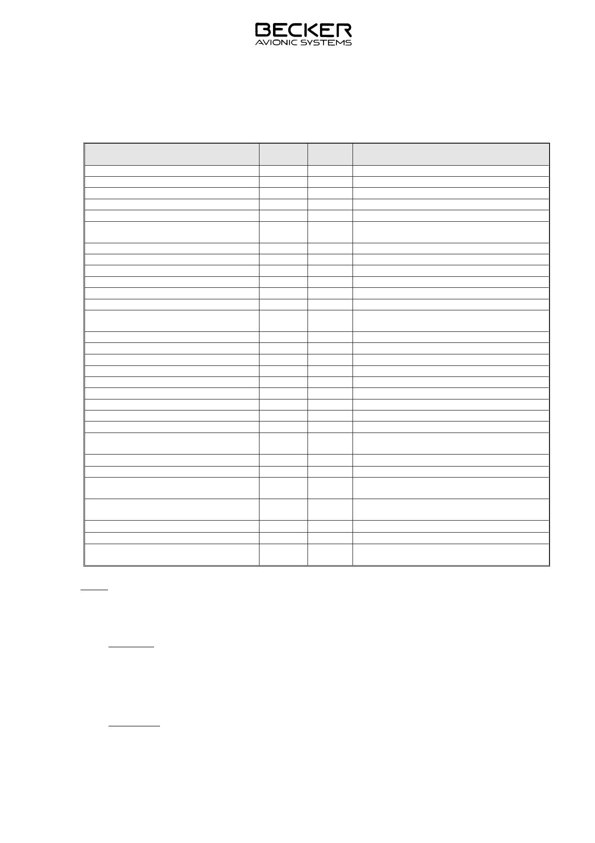
C. Environmental qualification
EUROCAE/RTCA ED-14D/DO-160D
Condition Section Cat. Description
Temperature and Altitude 4.0 A4
Low Ground Survival Temperature 4.5.1 A4 -40 deg C
Low Operating Temperature 4.5.1 A4 -15 deg C
High Ground Survival Temp. 4.5.2 A4 +85 deg C
High Ope ra ting Temp. 4.5.2 A4 +55 deg C
In-flight Loss of Coo ling 4.5.4 Z No for ced coo ling re qui red – No test
re qui red
Al ti tu de 4.6.1 A4 20,000 ft
De com pres si on 4.6.2 A4 20,000 ft
Over pres su re 4.6.3 A4 -15,000 ft
Tem pe ra tu re Va ria ti on 5.0 B 5 deg C/min
Hu mi di ty 6.0 A Standard humidity environment
Shock and Crash Sa fe ty 7.0 B Fixed-wing aircrafts and helicopters
Vi brat ion 8.0 S
U
Cat. S, vi brat ions test cur ve M
Cat. U, vi brat ions test cur ve G
Ex plo si on Pro of ness 9.0 X No test required
Wa ter pro of ness 10.0 X No test required
Fluids Sus cep ti bi li ty 11.0 X No test required
Sand and Dust 12.0 X No test required
Fun gus Re sis tan ce 13.0 X No test required
Salt Spray 14.0 X No test required
Mag ne tic Ef fect 15.0 Z 1 deg deflection at 0.3 m
Po wer In put 16.0 B
Vol ta ge Spi ke 17.0 A
Au dio Freq. Con duc ted Sus cep ti bi -
li ty
18.0 X
In du ced Sig nal Sus cep ti bi li ty
19.0 A Interference-free operation desirable
Ra dio Fre quen cy Sus cep ti bi li ty 20.0 WW Interim High Intensity Ratiated Fields
Spu ri ous RF Emis si on 21.0 B Equipment where interference should
be controlled to a tolerable level
Light ning In du ced Tran sients Sus -
cep ti bi li ty
22.0 A3
E3
Pin test waveform A, level 3
Cable bundle test waveform E, level 3
Light ning Di rect Ef fects
23.0 X No test required
Icing 24.0 X No test required
Elec tro sta tic Disch ar ge 25.0 A Equipment operated in an aerospace
environment
Note: With exception of the overpressure test (Section 4.6.3 of EUROCAE/RTCA ED-14D/
DO-160D) all qualification tests were applied to the combination BECKER BXP6401
and BECKER BE6400.
4. Soft wa re
The Blind Encoder BE6400-01-(XX) is con trol led by a microcontroller. The soft wa re
cri ti ca li ty is de ter min ed to be Le vel C in ac cor dan ce with EU ROCAE/RTCA do cu -
ment ED12B/DO-178B.
5. Approvals
EASA ETSO-C88a
INSTALLATION AND OPERATION
BE6400-01-(XX)
Page 1-3
34-50-11
February 2007
6. Equipment
Blind Encoder BE6400-01-(01) Article-No. 0592.137-915
7. Ac ces so ries
Air pressure tube, e.g. Polyurethane tube, blue from LEGRIS
(outer diameter 6 mm, inner diameter 4 mm)
Manual “Installation and Operation” Article-No. 0594.547-071
INSTALLATION AND OPERATION
BE6400-01-(XX)
Page 1-4
34-50-11
August 2006
TAB LE OF CON TENTS
IN STAL LA TI ON Page
1. Ge ne ral 2-1
2. In spec ti on be fo re in stal la ti on 2-1
3. Me cha ni cal in stal la ti on 2-1
4. Air craft wi ring 2-2
5. Configuration setting of the transponder 2-2
6. Chec king af ter in stal la ti on 2-3
Fig. 2-1 Assembled Blind Encoder with Mode S transponder 2-1
Fig. 2-2 Outline dimensions BE6400-01-(XX), measures in mm 2-4
INSTALLATION AND OPE RA TI ON
BE6400-01-(XX)
Page II-I
34-50-11
May 2007
BLANK
INSTALLATION AND OPE RA TI ON
BE6400-01-(XX)
Page II-II
34-50-11
August 2006
IN STAL LA TI ON
1. Ge ne ral
In stal la ti on of the Blind Encoder BE6400-01-(XX) is de pen ding on the air craft type
and its clas si fi ca ti on as well as re qui re ments. The re fo re, only ge ne ral in for ma ti o n
can be pro vi ded in this sec ti on.
2. In spec ti on be fo re in stal la ti on
Be fo re the blind encoder is in stal led on an air craft, a vi su al in spec ti on for pos si ble
trans port da ma ges shall be done.
Please look out for the following defects:
(1) Dirt, dents, scratches, corrosion, broken fastening elements on connector
housing and housing parts.
(2) Dirt and scratches on nameplate and inscriptions.
(3) Dirt, bent or broken pins, cracked insert of equipment connector.
(4) Missing screws.
3. Me cha ni cal in stal la ti on
The blind encoder is designed for installation in an aircraft together with the Becker
Mode S transponder BXP6401or BXP6402. The equipment is capable of being
mounted to the J8 unit connector of the transponder. To the mechanical stabilization
the blind encoder must be fastened with a device at the housing of the transponder
(see Fig. 2-1).The outline dimensions of the blind encoder are given in Fig. 2-2.
The sensor of the blind encoder must be connected with the outer air over a flexible
air pressure tube (see accessories in section General Description). The inner
diameter of the air pressure tube must be 4 mm. The sensor therefore gets the outer
air pressure of the respective aircraft for the altitude measuring.
Note: The protection cover must be removed before connect the air pressure tube.
Fig. 2-1 Assembled Blind Encoder with Mode S transponder
IN STAL LA TI ON AND OPE RA TI ON
BE6400-01-(XX)
Page 2-1
34-50-11 February 2007
4. Air craft wi ring
A. Pin connections of the unit connector P8 (for BXP6401 and BXP6402)
The unit con nec tor type is a D-SUB 25-pole male connector.
Pin
ID
Name Direction Function
1 - - -
2 - - -
3 GND - Signal and supply return
4 SUPP In Equipment supply
5 - - -
6 - - -
7 - - -
8 - - -
9 - - -
10 - - -
11 - - -
12 ALTS- Out Altimeter receiver input inverting
13 ALTS+ Out Altimeter receiver input-non-inverting
14 - - -
15 - - -
16 - - -
17 - - -
18 - - -
19 - - -
20 - - -
21 GND - Signal and supply return
22 - - -
23 - - -
24 - - -
25 - - -
5. Configuration setting of the transponder
After the installation of the equipment, the configuration setting of the transponder
must be adapted in the following way (supposing that programmed Address Module
and antenna are connected):
(1) Switch the transponder to “SBY” and press the “SEL” button.
(2) Turn the rotary knob until “INS” appears in the lower left corner of the display.
(3) Press the rotary button. “PASSWORD” appears in the display.
(4) Enter “6435” by turning the rotary knob and press it to go to the next digit.
(5) Press the “STO” button. The display shows ALTM SELECT”.
(6) Check if ”UPS AT” is marked. If yes, go to (9).
(7) Turn the rotary knob until “UPS AT” is highlighted.
(8) Press the “STO” button to select “UPS AT”.
INSTALLATION AND OPERATION
BE6400-01-(XX)
Page 2-2
34-50-11 May 2007
(9) Press the rotary button until “SPECIALS” appears in the display.
(10) Check if “ALTM HIGH RESOL” is marked. If yes, go to (13).
(11) Turn the rotary button to select “ALTM HIGH RESOL”.
(12) Press the “STO” button to set high resolution.
(13) Press the rotary button until “ERROR LATCHES” appears in the display.
(14) Turn the rotary button to select “CLEAR LATCHES”.
(15) Press the “STO” button to clear the error latches.
(16) Press the SEL” button to leave the menu.
Configuration is complete now.
6. Chec king af ter in stal la ti on
A. Ge ne ral
Af ter the in stal la ti on, check the blind encoder in con juncti on with the corres-
ponding transponder to en su re sa tis fac to ry ope ra ti on of the equipment.
B. Pre-flight check
Switch the Mode S transponder to “ALT” and check the correct flight level is
displayed.
IN STAL LA TI ON AND OPE RA TI ON
BE6400-01-(XX)
Page 2-3
34-50-11 May 2007
Fig. 2-2 Outline dimensions BE6400-01-(XX), measures in mm
INSTALLATION AND OPERATION
BE6400-01-(XX)
Page 2-4
34-50-11 May 2007
  • Page 1 1
  • Page 2 2
  • Page 3 3
  • Page 4 4
  • Page 5 5
  • Page 6 6
  • Page 7 7
  • Page 8 8
  • Page 9 9
  • Page 10 10
  • Page 11 11
  • Page 12 12
  • Page 13 13
  • Page 14 14
  • Page 15 15
  • Page 16 16
  • Page 17 17
  • Page 18 18
  • Page 19 19
  • Page 20 20
  • Page 21 21
  • Page 22 22
  • Page 23 23
  • Page 24 24

Becker BE6400 for BXP6401 User manual

Type
User manual
This manual is also suitable for

Ask a question and I''ll find the answer in the document

Finding information in a document is now easier with AI