Page is loading ...

Model: 16608600950
OWNER’S MANUAL
PLEASE CAREFULLY READ THIS ENTIRE MANUAL BEFORE
OPERATING YOUR NEW ELLIPTICAL!

T ABLE OF
C ONTEN T S
Product Registration 3
Important Safety Instructions 4
Important Electrical Information 5
Important Operation Instructions 6
Transport Instructions 6
E95 Assembly Instructions 9
Elliptical Features 14
Operation of Your New Elliptical 15
Bluetooth® Connectivity 20
Programmable Features 21
Using Heart Rate Monitor 29
General Maintenance 32
Exploded View Diagram 35
Parts List 36
Manufacturer’s Limited Warranty 41
ATTENTION
THIS ELLIPTICAL IS INTENDED FOR RESIDENTIAL USE ONLY AND IS WARRANTED FOR THE
APPLICATION. ANY OTHER APPLICATION VOIDS THIS WARRANTY IN ITS ENTIRETY.

3
Dyaco Canada Inc. 2016
CONGRATULATIONS ON YOUR NEW ELLIPTICAL AND WELCOME TO THE SOLE FAMILY!
Thank you for your purchase of this quality Sole elliptical from Dyaco Canada Inc. Your new elliptical has been
manufactured by one of the leading fitness manufacturers in the world and is backed by one of the most
comprehensive warranties available. Dyaco Canada Inc. will do all we can to make your ownership experience as
pleasant as possible for many years to come.
If you have any questions about your new Sole product or questions about the warranty contact Dyaco Canada
Inc. at 1-888-707-1880.
Please take a moment at this time to record below the name of the dealer, their telephone number, and the date
of purchase for easy contact in the future. We appreciate your confidence in SOLE and we will always remember
that you are the reason that we are in business. Please complete and mail your registration card today and enjoy
your new elliptical.
Yours in Health,
Dyaco Canada Inc.
Name of Dealer
Telephone Number of Dealer
Purchase Date
PRODUCT REGISTRATION
RECORD YOUR SERIAL NUMBER
Please record the Serial Number of this fitness product in
the space provided below.
Serial Number
REGISTER YOUR PURCHASE
The self-addressed product registration card must be completed in full and returned to Dyaco Canada Inc.
You can also go to www.solefitness.ca to register online.

Dyaco Canada Inc. 2016
4
IMPO R T ANT
SAF E T Y
INST R U C TIONS
WARNING - Read all instructions before using this appliance.
DANGER - To reduce the risk of electric shock disconnect your SOLE elliptical from the electrical
outlet prior to cleaning and/or service work.
WARNING - To reduce the risk of burns, fire, electric shock, or injury to persons, install the
elliptical on a flat level surface with access to a a110-volt, 15-amp grounded outlet with only the
elliptical plugged into the circuit.
DO NOT USE AN EXTENSION CORD UNLESS IT IS A 14 AWG OR BETTER, WITH ONLY ONE
OUTLET ON THE END: DO NOT ATTEMPT TO DISABLE THE GROUNDED PLUG BY USING
IMPROPER ADAPTERS, OR IN ANY WAY MODIFY THE CORD SET.
A serious shock or fire hazard may result along with computer malfunctions. See Grounding Instructions, page 5.
Do not operate elliptical on deeply padded, plush or shag carpet. Damage to both carpet
and elliptical may result.
Keep children under the age of 13 away from this machine. There are obvious pinch points
and other caution areas that can cause harm.
Keep hands away from all moving parts.
Never operate the elliptical if it has a damaged cord or plug. If the elliptical is not working
properly, call your dealer.
Keep the cord away from heated surfaces.
Do not operate where aerosol spray products are being used or where oxygen is being
administered. Sparks from the motor may ignite a highly gaseous environment.
Never drop or insert any object into any openings.
Do not use outdoors.
To disconnect, turn all controls to the off position and then remove the plug from the
outlet.
Do not attempt to use your elliptical for any purpose other than for the purpose it is
intended.
The hand pulse sensors are not medical devices. Various factors, including the user’s
movement, may affect the accuracy of heart rate readings. The pulse sensors are intended
only as exercise aids in determining heart rate trends in general.
Wear proper shoes. High heels, dress shoes, sandals or bare feet are not suitable for use on
your elliptical. Quality athletic shoes are recommended to avoid leg fatigue.
This appliance is not intended for use by persons with reduced physical, sensory or mental
capabilities, or lack of experience and knowledge, unless they have been given supervision
or instruction concerning use of the appliance by a person responsible for their safety.
SAVE THESE INSTRUCTIONS - THINK SAFETY!

5
Dyaco Canada Inc. 2016
IMPO R T ANT
ELE C TRI C AL
INST R U C TIONS
WARNING!
NEVER remove any cover without first disconnecting AC power.
If voltage varies by ten percent (10%) or more, the performance of your elliptical may be
affected. Such conditions are not covered under your warranty. If you suspect the voltage is low,
contact your local power company or a licensed electrician for proper testing.
NEVER expose this elliptical to rain or moisture. This product is NOT designed for use outdoors,
near a pool or spa, or in any other high humidity environment. The operating temperature
specification is 40 to 120 degrees Fahrenheit, and humidity is 95% non-condensing
(no water drops forming on surfaces).
G R OUNDING INSTRU C TIONS
This product must be grounded. If the elliptical should malfunction or breakdown, grounding
provides a path of least resistance for electric current, reducing the risk of electric shock. This
product is equipped with a cord having an equipment-grounding plug. The plug must be plugged
into an appropriate outlet that is properly installed and grounded in accordance with all local codes
and ordinances.
DANGER - Improper connection of the equipment-grounding conductor can result in a risk of
electric shock. Check with a qualified electrician or serviceman if you are in doubt as to whether
the product is properly grounded. Do not modify the plug provided with the product if it will not fit
the outlet; have a proper outlet installed by a qualified electrician.
This product is for use on a nominal 110-volt, 15-amp circuit, and has a grounding plug that looks
like the plug illustrated below. A temporary adapter that looks like the adapter illustrated below
may be used to connect this plug to a 2-pole receptacle as shown below if a properly grounded
outlet is not available. The temporary adapter should be used only until a properly grounded
outlet, (shown below) can be installed by a qualified electrician. The green colored rigid ear-lug,
or the like, extending from the adapter, must be connected to a permanent ground such as a
properly grounded outlet box cover. Whenever the adapter is used, it must be held in place by a
metal screw.

Dyaco Canada Inc. 2016
6
IMPO R T ANT
OPE R A TION
INST R U C TIONS
NEVER operate this elliptical without reading and completely understanding the results of
any operational change you request from the computer.
Understand that changes in resistance and incline do not occur immediately. Set your
desired resistance level on the computer console and release the adjustment key. The
computer will obey the command gradually.
NEVER use your elliptical during an electrical storm. Surges may occur in your household
power supply that could damage elliptical components. Unplug the elliptical during an
electrical storm as a precaution.
Use caution while participating in other activities while using your elliptical; such as watching
television, reading, etc. These distractions may cause you to lose balance; which may result
in serious injury.
Always hold on to a handle bar while making control changes (incline, level, etc.).
Do not use excessive pressure on console control keys. They are precision set to function
properly with little finger pressure. If you feel the buttons are not functioning properly with
normal pressure contact your SOLE dealer.
POWER CONNECTOR - FRONT, LEFT SIDE OF UNIT
T R ANSPO R T
INST R U C TIONS
The elliptical is equipped with two transport wheels which are engaged when the rear of the
elliptical is lifted.

7
Dyaco Canada Inc. 2016
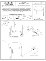
E 95
ASSEMB LY P A CK CHECKLIST
1
HARD W ARE
STEP 1
#181. 3/8” x 23 x 2T
Curved Washer (2 pcs)
#170. 5/16” x 20 x 1.5T
Flat Washer (4 pcs)
#164. 3/8” x 19 x 1.5T
Flat Washer (2 pcs)
#180. 3/8” x 2T
Split Washer (1 pc)
#141. M5 x 10mm
Phillips Head Screw (4 pcs)
#157. 3/8” x 7T
Nylon Nut (2 pcs)
#182. 5/16” x 1.5T
Split Washer (4 pcs)
#183. 5/16”
Star Washer (4 pcs)
#132. 3/8” x 3/4”
Hex Head Bolt (2 pcs)
#135. 5/16” x 2-1/4” Hex
Head Bolt (4 pcs)
#133. 3/8” x 1-1/2”
Hex Head Bolt (2 pcs)
#125. 3/8” x 2-1/4”
Hex Head Bolt (1 pc)

Dyaco Canada Inc. 2016
8
2
HARD W ARE
STEP 2
3
HARD W ARE
STEP 3
4
HARD W ARE
STEP 4
#132. 3/8” x 3/4”
Hex Head Bolt (2 pcs)
#134. 5/16” x 1-1/4”
Hex Head Bolt (2 pcs)
#165. 3/8” x 30 x 2T
Flat Washer (2 pcs)
#175. Ø25
Wave Washer (4 pcs)
#170. 5/16” x 20 x 1.5T
Flat Washer (2 pcs)
#159. 5/16” x 7T
Nylon Nut (2 pcs)
#75. Switch Wire Cap
(2 pcs)
#164. 3/8” x 19 x 1.5T
Flat Washer (8 pcs)
#157. 3/8” x 7T
Nylon Nut (6 pcs)
#206. 3/8” x 2-1/4”
Hex Head Bolt (6 pcs)
#181. 3/8” x 23 x 2T
Curved Washer (4 pcs)
#139. M5 x 15mm
Phillips Head Screw
(29 pcs)
#142. 3.5 x 12mm
Sheet Metal Screw
(18 pcs)
#145. M6 x 10mm
Phillips Head Screw
(4 pcs)

9
Dyaco Canada Inc. 2016
ASSEMB LY
T OOLS
E 95
ASSEMB LY
INSTRU C TIONS
PRE
- ASSEMB LY
1. Using a razor knife (Box Cutter) cut the outside, bottom, edge of box along
the dotted Line. Lift Box over the unit and unpack.
2. Carefully remove all parts from carton and inspect for any damage or missing
parts. If damaged parts are found, or parts are missing, contact your dealer
immediately.
3. Locate the hardware package. Remove the tools first. Remove the hardware
for each step as needed to avoid confusion. The numbers in the instructions
that are in parenthesis (#) are the item number from the assembly drawing
for reference
#184. 13/14mm Wrench (160mm)
#185. Short Phillips Head Screwdriver
#186. Phillips Head Screwdriver
#187. 12/14mm Wrench (160mm)

Dyaco Canada Inc. 2016
10
E 95
ASSEMBLY
INSTRU C TIONS
1
2
INCLINE
R AIL
& C ONSOLE
M AST
See Page 11 for Illustration
1. Install the Incline Rail Assembly (2) into the U-channel bracket of the Main
Frame (1). Secure with the six bolts & associated hardware as follows: From the
sides install two Hex Head Bolts (133) with two Flat Washers (164) and two
Nylon Nuts (157). From the top install four Hex Head Bolts (135), four Split
Washers (182), four Flat Washers (170), and four Star Washers (183), and
tighten with the Wrenches provided (184 & 187).
2. Connect the three Wire Harness (48) to the female receiver cable coming from
the Incline Rail Assembly (2). Connect the Three pin position Sensor Connector
(49) to the female receiver coming from the Incline Rail Assembly (2). Mate red,
white, and black wires together.
3. Locate the Console Mast (12) and Console Mast Cover (96) and slide the cover
onto the mast as far as it will go. Make sure the Console Mast Cover is facing
the correct way. At the top opening of the Main Frame of the elliptical is a
Computer Cable (50). Secure the free end of the twist tie that exits the bottom
of the Console Mast (12) to this cable. Pull the opposite end of this twist tie up
through the Console Mast (12) until the cable exits the top.
Install the Console Mast (12) into the receiving bracket on the top of the Main
Frame (1). Pull slightly on the Computer Cable at the top of the mast while
installing. This will ensure the cable does not get pinched and shorted during
Console Mast Assembly.
4. Put one Split Washer (180) onto the Long Hex Head Bolt (125) and install
through the left side of the receiving bracket into the Console Mast (12). Put
the two Curved Washers (181) onto the two Short Hex Head Bolts (132) and
install through the front of the console mast. Using Wrench (184), tighten the
(132) bolts first, then the (125) bolt, and lastly the fourth bolt, which is pre-
installed, firmly. These bolts should be tightened as much as you possibly can.
This is the main joint of the unit. If not tightened sufficiently, this could lead to noise
and instability issues.
5. Plug all of the connectors into the back of the console; Computer Cable (50),
two Hand pulse Cables (56 & 56-1), Resistance Switch Wire (60) and Incline
Switch Wire (59). Secure the Console (45) on the console mounting plate with
four Phillips Head Screws (141) using the Screw Driver (186). Note: there will be an
empty four pin port on the back of the console. This model doesn’t use this port.
L OWER
HANDLE B AR ARMS
See Page 11 for Illustration
1. Install two Wave Washers (175) onto the Left and Right sides of the Handle Bar
axle.
2. Slide the Left (13) and Right (14) lower handle bar arms onto the appropriate
side of the axle. The handlebars have a small sticker on them indicating L (left)
and R (right). Make sure the handlebars are facing the correct direction – see illustration.
3. Install two Flat Washers (165) onto the two Hex Head Bolts, (132) and install
and tighten in the threaded holes in the ends of the axle with a Wrench (187).
4. Untie the wire holding the Sleeve Spacer (24) in place on the rod-end of the
Lower Handle Bar Arms (13 & 14). Align the hole in the rod ends with the hole
in the brackets of the left and right Handle Bar (13 & 14). The end of connecting
arms should be positioned inside the Handle Bar bracket. Secure with a Hex Head
bolt (134), Flat Washer (170) and Nylon Nut (159) by using the Wrenches provided
(184 & 187).
#125. 3/8” x 2-1/4” Hex
Head Bolt (1 pcs)
#132. 3/8” x 3/4”
Hex Head Bolt (2 pcs)
#133. 3/8” x 1-1/2” Hex
Head Bolt (2 pcs)
#135. 5/16” x 2-1/4” Hex
Head Bolt (4 pcs)
#141. M5 x 10mm
Phillips Screw (4 pcs)
#157. 3/8” x 7T Nylon Nut
(2 pcs)
#164. 3/8” x 19 x 1.5T Flat
Washer (2 pcs)
#170. 5/16” x 20 x 1.5T
Flat Washer (4 pcs)
#180. 3/8” x 2T Split
Washer (1 pc)
#181. 3/8” x 23 x 2T
Curved Washer (2 pcs)
#182. 5/16” x 1.5T Split
Washer (4 pcs)
#183. 5/16”
Star Washer (4 pcs)
#132. 3/8” x 3/4”
Hex Head Bolt (2 pcs)
#134. 5/16” x 1-1/4”
Hex Head Bolt (2 pcs)
#159. 5/16” x 7T
Nylon Nut (2pcs)
#165. 3/8” x 30mm
Flat Washer (2 pcs)
#170. 5/16” x 20 x 1.5T
Flat Washer (2 pcs)
#175. 25mm
Wave Washer (4 pcs)
HARDWARE STEP 1
HARDWARE STEP 2


Dyaco Canada Inc. 2016
12
3
4
UPPER
HANDLE B AR ARMS
See Page 13 for Illustration
1. Connect the Swing Arm (L-10) to the left Lower Arm (13) and connect the Swing
Arm (R-11) to the right Lower arm (14) , and secure them with six Hex Head Bolts
(206), eight Flat Washers (164), four Curved Washers (181) and six Nylon Nuts
(157) using the 13/14mm Wrench (184) and 12/14mm Wrench (187).
2. Connect the two wires (L-61 to 60 & R-61 to 59) on the L & R sides together and
store the excess wire, including plastic connectors, back inside Console Mast (12).
Place the Rubber Grommets (75) over the wire on each side and snap them into the
holes of the console mast.
PLASTIC
P AR T S
See Page 13 for Illustration
Use either Screw Driver (185 or 186) to secure the following plastic parts.
1. Match up the Console Covers (196 & 197) and secure with three Phillips Head
Screws (139) and two Sheet Metal Screws (142).
2. Match up the Inner Connecting Arm Covers (111 & 112). Install the covers with two
Sheet Metal Screws (142) and two Phillips Head Screws (139) to each joint.
3. Match up the outer Connecting Arm Covers (109 & 110) and install onto the Left
and Right Connecting Arms (8 & 9). Secure each side with a Phillips Head
Screw (139) and two Sheet Metal Screws (142). Make sure you position the
covers with the arrows pointing up. If they are installed incorrectly, they will break.
5. Install Sliding Wheel Covers (104) on each side and secure with four Phillips Head
Screws (139).
6. Install the two Stabilizer Covers (117 and 118) on the middle stabilizer bar with two
Phillips Head Screws (139).
6. Install the Front Stabilizer Cover (103) on the front stabilizer with two Phillips
Head Screws (139).
7. Install the two incline Cover Brackets (25), with the hole for mounting the plastic
cover on the bent tab facing rearward, and secure them on the Incline Rail
Assembly (2) with four Phillips Head Screws (145). Install the Rear Incline Bar
Cover (115) on the rail base with two Screws (139).
8. Install the Rear Stabilizer Cover (116) on the Rear Stabilizer with four Phillips
Head Screws (139).
9. Mate the Front Handle Bar Cover (L-105) and the Rear Handle Bar Cover (L- 106)
together on the Left Arm and secure with four Sheet Metal Screws (142) using
the Phillips Head Screw Driver (186). Repeat the same procedure for #’s 107 & 108
on the right side.
10. This step to be performed after the elliptical power is plugged in. Elevate the incline
to Level 8 and install the Incline Rail Front Cover (113) up against the middle
stabilizer tube with four Phillips Head Screws (139)
#75. Switch Wire Cap
(2 pcs)
#157. 3/8” x 7T Nylon
Nut (6pcs)
#164. 3/8” x 19 x 1.5T
Flat Washer (8 pcs)
#181. 3/8” x 23 x 2T
Curved Washer (4 pcs)
#206. 3/8” x 2-1/4” Hex
Head Bolt (6 pcs)
#139. M5 x 15mm
Phillips Head
Screw (29 pcs)
#142. 3.5 x 12mm Sheet
Metal Screw (18 pcs)
#145. M6 x 10mm
Phillips Head Screw
(4 pcs)
HARDWARE STEP 3
HARDWARE STEP 4


Dyaco Canada Inc. 2016
14
ELLIPTI C AL
FE A TURES
INCLINE ADJUSTMENT
The E95 has an incline feature that will further increase the variety of your workouts. When the
incline is at its lowest position you get a normal elliptical workout. As the incline increases you
will feel your knees rise higher with each step; which means you are involving more muscle
fibers, due to the increased range of motion.
The E95 has a computer controlled power incline. The power incline is controlled by buttons on
the console and swing arms and will automatically adjust via the incline motor during the built -in
workout program.
ADJUSTABLE FOOT PEDAL
The Sole E95 also features a unique 10 position pedal adjustment for maximum comfort and the
most natural elliptical motion. The pedal can be adjusted by turning the knob as shown in the
picture.

15
Dyaco Canada Inc. 2016
DISPLAY
PROGRAM BUTTONS
(Manual, Hill, Fat Burn,
Cardio, Strength, Interval,
2 User, 2HR)
OPE R A TION OF
Y OUR
ELLIPTI C AL
GETTING FAMILIAR WITH THE CONTROL PANEL
E95 CONSOLE
POWER UP
When power is connected to the elliptical the console will automatically power up. These models
are connected directly to 110-volt, 15-amp and there is a power switch located where the line
cord plugs into the unit on the left side near the front (See page 6 for location).
When it is first powered on, the boot screen will display Odometer readings for a short time, Total
time will show how many hours the elliptical has been in use and the Total distance will show
how many miles (or Kilometers if the elliptical is set to metric readings) the elliptical has gone.
The elliptical will then enter idle mode, which is the starting point for operation.
COOLING FAN
SPEAKER
FAN POWER SWITCH
HEADPHONE JACK
AUDIO IN JACK
(MP3, CD, OR
SMARTPHONE)


17
Dyaco Canada Inc. 2016
CONSOLE OPERATION
QUICK START
This is the quickest way to start a workout. After the console powers
up you just press the Start key to begin, this will initiate the Quick
Start mode. In Quick Start, the time will count up from zero. The
resistance level and incline can be adjusted manually by pressing the
Level ▲/▼ keys. The dot matrix display will be showing a track with
a blinking dot indicating your progress as it travels around the track.
BASIC INFORMATION
When you press the Display button, the data shown on the screen will change. If you don't press the
Display button a 2nd time, the screen will return to the workout screen after 3 seconds.

Dyaco Canada Inc. 2016
18
The Elliptical has a built in heart rate monitoring system. Simply grasping the Contact Heart Rate
Sensors on the stationary handle bars or wearing the chest strap transmitter will start the heart (see
Heart Rate Programs) icon blinking (this may take a few seconds). The Pulse Window will display your
heart rate in beats per minute and the HR bar graph will show your current % in relation to projected
heart rate maximum. The chest strap is a more accurate and reliable method of heart rate reading. The
hand pulse sensors are subject to inaccurate readings depending on user physiology and workout
habits including how one grips the sensors or how sweaty their hands are.
The Stop button actually has several functions.
Pressing the Stop key once during a program will pause the program for
5 minutes. If you need to get a drink, answer the phone or any of the
many things that could interrupt your workout, this is a great feature. To
resume your workout during pause just press the Start key. If the Stop
button is pressed twice during a workout the program will end and a
Workout Summary is displayed.
If the Stop key is held down for 3 seconds the console will perform a
complete Reset. During data entry for a program the Stop key performs a
Previous Screen function. This allows you to go back one step in the
programming each time you press the Stop key.
There is an Audio In Jack ( ) on the front of the console and built-in speakers. You may plug any low-
level audio source signal into this port. Audio sources include MP3, iPod, portable radio, CD player or
even a TV or computer audio signal. There is also a Headphone Jack ( ) for private listening.
PROGRAMMING THE CONSOLE
Each of the programs can be customized with your personal information and changed to suit your
needs. Some of the information asked for is necessary to ensure the readouts are correct. You will be
asked for your Age and Weight. Entering your Age is necessary during the Heart Rate control program
to ensure the correct settings are entered in the program; entering your Weight aides in calculating a
more correct Calorie reading. Although we cannot provide an exact calorie count we do want to be as
close as possible.
Setting Age,Weight and Time page

19
Dyaco Canada Inc. 2016
A message about Calories: Calorie readings on every piece of exercise equipment, whether it is in a
gym or at home, are not accurate and tend to vary widely. They are meant only as a guide to monitor
your progress from workout to workout. The only way to measure your calorie burn accurately as in a
clinical setting connected to a host of machines. This is because every person is different and burns
calories at a different rate.
ENTERING A PROGRAM AND CHANGING SETTINGS
Press each program button to scroll through the program selections. The profile for each program will
be displayed in the window. It will show the incline profile also when the Display key is pressed. Press
the Enter key to select a program and begin customizing the settings. If you want to work out without
entering new settings, then just press the Start key. This will bypass the programming of data and take
you directly to the start of your workout. If you want to change the personal settings, then just follow
the instructions in the Window. If you start a program without changing the settings, the default
settings will be used.
Note: Age and Weight default settings will change when you enter a new number. So the last Age and
Weight entered will be saved as the new default settings. If you enter Age and Weight the first time
you use the elliptical you will not have to enter it every time you work out unless either Age or Weight
has changed or someone else enters different Age and Weight.

Dyaco Canada Inc. 2016
20
New Sole App to be used in conjunction with select Apple & Android devices!
In order to help you achieve your exercise goals, Sole has added an exciting new feature to all of our
products. Your new exercise machine comes equipped with a Bluetooth
®
transceiver that will allow it to
interact with selected phones or tablet computers via the Sole Fitness App.
Just download the free Sole Fitness App from the Apple Store or Google Play, and then follow the
instructions in the App to sync with your exercise machine. This allows you to view current workout
data in three different Display screens on your device. Easily switch back and forth from the workout
display view to internet/social media/email sites via icons on the display screen. When your workout is
finished, the data is automatically saved to the built-in personal calendar for future reference.
Our new Sole Fitness App also allows you to sync your workout data with one of many fitness cloud sites
we support: iHealth, MapMyFitness, Record MyFitnessPal or Fitbit.
Syncing the App with your exercise machine:
After downloading the App, make sure Bluetooth® is enabled on your device, then click the icon in the
top left corner to search for Sole equipment.
After the equipment is detected, click Connect. When the App and equipment are synced, the
Bluetooth® icon on the equipment’s console will light up. You may now start using your new Sole
product!
*Note: Your device will need to be running on a minimum operating system of iOS 7 or Android 4.4 for
the Sole Fitness App to operate properly.
/