Page is loading ...

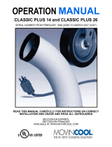
OPERATION MANUAL
CM25
Unit Serial Number Range: 1009XXXXC25 to Present
(From October 2009 to Present)
READ THIS MANUAL CAREFULLY FOR INSTRUCTIONS ON CORRECT
INSTALLATION AND USAGE, AND READ ALL SAFEGUARDS.
SECCIÓN EN ESPAÑOL
SECTION EN FRANÇAIS
AVAILABLE AT WWW.MOVINCOOL.COM

SERIAL NUMBER LOCATION AND IDENTIFICATION
Nameplate Label Position
Nameplate Label
COOLING AMPS. WITH PUMP
COMPR. OUTPUT
REFRIGERANT/TOTAL CHARGE
DESIGN PRESSURE LO/HI
PART NO./WEIGHT
SERIAL NO.
Month
Model
Sequential
Number
Year
▲▲ XXXX ###
© 2013 DENSO PRODUCTS AND SERVICES AMERICAS, INC.
All rights reserved. This book may not be reproduced or copied, in
whole or in part, without the written permission of the publisher.
DENSO PRODUCTS AND SERVICES AMERICAS, INC. reserves the
right to make changes without prior notice. MovinCool®, Office Pro®
and SpotCool® are registered trademarks of DENSO Corporation.

OPERATION MANUAL
CM25

Table of Contents
SERIAL NUMBER LOCATION AND IDENTIFICATION ................................... 2
FOREWORD ...................................................................................................... 6
Definition of Terms................................................................................ 6
GENERAL WARNINGS & CAUTIONS.............................................................. 6
UNPACKING ...................................................................................................... 7
INVENTORY....................................................................................................... 8
INSTALLATION ................................................................................................. 9
Unit Overview ........................................................................................ 9
Clearance Requirement ...................................................................... 10
Mounting CM25 to Roof Structure ..................................................... 11
Drain Hose Connection....................................................................... 16
Packing Attachment............................................................................ 17
Ducting With Typical Drop Ceiling..................................................... 18
Condenser Duct Installation (Optional)............................................. 19
Power Supply and Field Wiring Connection..................................... 20
DIP Switch Configuration and Setting............................................... 22
Supplied Wall Mounted Controller Connection ................................ 24
Field-Supplied Millivolt Wall Thermostat Connection...................... 29
Warning Signal Connection (Output Signal)..................................... 32
Fire Alarm Connection (Input Signal) ................................................ 34
FEATURES OF WALL MOUNTED CONTROLLER........................................ 36
FEATURES OF CM25...................................................................................... 37
OPERATION (Wall Mounted Controller ONLY) ............................................ 38
Control Panel ....................................................................................... 38
Standby Mode...................................................................................... 41
Set Clock .............................................................................................. 41
Operate in COOL Mode ....................................................................... 42
Operate in FAN ONLY Mode............................................................... 43
Change Mode....................................................................................... 43
Change Temperature Scale ................................................................ 43
Keypad Lock ........................................................................................ 43
Program Feature.................................................................................. 43
Program Setting .................................................................................. 44
Select Program Sequence Number.................................................... 45
Set Start Time and Operation Mode................................................... 45
Set Stop Time ...................................................................................... 46
Exit Program Mode.............................................................................. 46
View Program ...................................................................................... 46
Edit Program........................................................................................ 47
Delete Program.................................................................................... 47

Run and Stop Program ....................................................................... 47
Program Plan Sheet ............................................................................ 48
SELF-DIAGNOSTIC CODES & BUZZER PATTERN...................................... 49
Self-Diagnostic Codes ........................................................................ 49
Table of Self-Diagnostic Codes.......................................................... 49
Buzzer Pattern ..................................................................................... 50
DAILY INSPECTION & MAINTENANCE......................................................... 51
Cleaning Air Filters ............................................................................. 51
Cleaning Condenser Air Intake .......................................................... 51
Ground Fault Breaker Testing............................................................ 51
TROUBLESHOOTING ..................................................................................... 52
TECHNICAL SPECIFICATIONS...................................................................... 58

6
FOREWORD
Congratulations on purchasing the MovinCool air conditioner. This manual
explains how to assemble, install and operate the MovinCool CM25 air
conditioning unit. Please read this operation manual thoroughly to familiarize
yourself with the features of the unit and to ensure years of reliable operation.
You may also find it useful to keep this operation manual on hand for reference.
Components and/or procedures are subject to change without prior notice.
Definition of Terms
WARNING: Describes precautions that should be observed in order
to prevent injury to the user during installation or unit operation.
CAUTION: Describes precautions that should be observed in order
to prevent damage to the unit or its components, which may occur
during installation or unit operation if sufficient care is not taken.
Note: Provides additional information that facilitates installation or unit operation.
GENERAL WARNINGS & CAUTIONS
1. All electrical work should only be performed by qualified electrical personnel.
Repair to electrical components by non-certified technicians may result in
personal injury and/or damage to the unit. All electrical components replaced
must be genuine MovinCool parts, purchased from an authorized reseller.
2. Installation should be conducted by qualified technician only. DENSO and
DENSO affiliate are not responsible for injuries and/or damages caused by
improper installation.
3. Disconnect power before any electrical installation. Beware that some residual
voltage may remain in the unit immediately after the power is disconnected.
4. The power supply for this unit should be a dedicated single outlet circuit with
UL recognized short-circuit and ground-fault protective breaker.
5. Do not place water or any other liquid on the unit. This can cause damage to
the unit and increase the risk of electrical shock.
6. Do not sit or stand on the unit.
7. Do not place hands or any object in the cool air outlet or exhaust duct.
Touching the fan, which is rotating at a high speed, is very hazardous.


8
INVENTORY
After unpacking your MovinCool unit, please check to make sure you have the
following items:
1. CM25 MovinCool Unit (1)
2. Operation Manual/Product
Registration (1)
3. Clip (1)
4. Packing (1)
5. Vibration Isolator (4)
6. Wall Mounted Controller (1)
7. Shield Wire (1)
8. Screw (4)
Note: If any of these items were not included in the box or appear damaged,
please contact your MovinCool reseller for replacement.
CM25 UNIT WALL MOUNTED CONTROLLER
SCREW FOR WALL
MOUNTED CONTROLLER
OPERATION MANUAL /
PRODUCT REGISTRATION
CLIP
VIBRATION ISOLATOR
PACKING (1.8 x 43.9 x 0.2 in)
SHIELD WIRE FOR WALL
MOUNTED CONTROLLER (12 ft)

9
INSTALLATION
Unit Overview
WARNING: Remove protective cardboard from condenser air intake
after installation.
COOL AIR EXHAUST
(12 in DIA. FLANGE)
DRAIN PIPE FOR PUMP
CONDENSER (HOT) AIR EXHAUST
EVAPORATOR (ROOM)
AIR INTAKE
(12 in DIA. FLANGE)
MOUNTING HOLES
CONDENSATE PAN DRAIN
FOR MAINTENANCE
SERVICE PANEL
WALL MOUNTED CONTROLLER/
MILLIVOLT WALL THERMOSTAT
WIRE INLET
CONDENSER AIR INTAKE
POWER CORD INLET
SIGNAL WIRE INLET
STOP SWITCH

10
INSTALLATION (cont.)
Clearance Requirement
51.3
53.0
All dimensions are in inches.
Unit Weight: 310 lb (140 kg)
29.8
DIA. 0.6
4.0
15.7
DIA. 11.8
DIA. 11.8
14.4
4.0
31.5
0.6
11.4
20.1
14.4
6.5
4.0
WALL
INTAKE
Minimum
clearance
20.0 in
from wall
Minimum
clearance
40.0 in
from wall
EXHAUST
CEILING
Top of the unit should not contact
any building structure or object.
WALL

11
INSTALLATION (cont.)
Mounting CM25 to Roof Structure
Be sure to securely anchor the top ends of the suspension rods. Make sure all nuts
are tight. Be sure to follow all applicable codes.
The unit is usually mounted above the ceiling and must be securely mounted to
the roof structure. The ceiling support of the existing building may require
reinforcements.
WARNING: Be sure that the supporting roof structure is capable of
supporting the weight of the unit, mounting hardware and the
accessories. Roof structure should be capable to support four
times of total weight or more. Unit weight is 310 lb (140 kg).
The recommended clearance between ceiling grids and building structural
member is the unit height plus 3.0 inch (76 mm).
All mounting hardware except vibration isolators is field supplied.
Use the following hardware.
Hardware (Quantity) Size
Threaded suspension rod (4)
Nut (12)
Washer (4)
½ in (Min. 310 lb (140 kg) load capability)
½ in
½ in

12
INSTALLATION (cont.)
Mounting CM25 to Roof Structure (cont.)
Example of Mounting with Pallet
1. Install four (4) suspension rods by suspending them from suitable building
structure members. Locate the rods so that they will align with four mounting
holes that are part of the unit base. Make sure to securely anchor the top ends
of the suspension rods and tighten all nuts.
2. Insert four (4) nuts (top) to the suspension rods before mounting the unit (12.0
inch minimum height from the bottom end of the suspension rods).
3. Locate the rods so that they will align with four mounting holes. Enter the lifts
into pallet openings. Slowly lift up the unit with the pallet.
12.0 in
Min.
29.8 in
51.3 in
THREADED
SUSPENSION ROD
ROOF STRUCTURE
NUT (top)
LIFTS
UNIT
PALLET
SUSPENSION ROD
MOUNTING HOLE

13
INSTALLATION (cont.)
Mounting CM25 to Roof Structure (cont.)
Example of Mounting with Pallet
4. Insert the suspension rods
through the mounting holes of
unit and pallet. Then install
vibration isolators, washers,
nuts (middle) and jam nut
(bottom) to be same level for all
four mounting positions.
5. Slowly lower the pallet with the lifts.
6. Make sure the unit is level.
Level must be less than 2° incline.
If the unit is not level, align the nut (middle) to level.
CAUTION: If level is more than 2° incline, condensation water
leakage may occur.
7. Tighten the jam nut (bottom).
Tightening torque for jam nut: Approx. 3.02 ft•lbf (4.1 N•m)
8. Tighten the nut (top) by hand until it is secured against the base frame.
SUSPENSION ROD
NUT (top)
MOUNTING HOLE
VIBRATION ISOLATOR
PALLET
WASHER
NUT (middle)
JAM NUT (bottom)
LIFTS
PALLET

14
INSTALLATION (cont.)
Mounting CM25 to Roof Structure (cont.)
Example of Mounting without Pallet
1. Install four (4) suspension rods by suspending them from suitable building
structure members. Locate the rods so that they will align with four mounting
holes that are part of the unit base. Make sure to securely anchor the top ends
of the suspension rods and tighten all nuts.
2. Insert four (4) nuts (top) to the suspension rods before mounting the unit (12.0
inch minimum height from the bottom end of the suspension rods).
3. Locate the rods so that they will align with four mounting holes. Slide the unit
from the pallet onto the lifts. Slowly lift up the unit.
12.0 in
Min.
29.8 in
51.3 in
THREADED
SUSPENSION ROD
ROOF STRUCTURE
NUT (top)
UNIT
PALLET
LIFTS
MOUNTING HOLE
SUSPENSION ROD

15
INSTALLATION (cont.)
Mounting CM25 to Roof Structure (cont.)
Example of Mounting without Pallet
4. Insert the suspension rods
through the mounting holes of
the unit. Then install vibration
isolators, washers, nuts
(middle) and jam nut (bottom) to
be same level for all four
mounting positions.
5. Slowly lower the lifts.
6. Make sure the unit is level. Level must be less than 2° incline. If the unit is
not level, align the nut (middle) to level.
CAUTION: If level is more than 2° incline, condensation water
leakage may occur.
7. Tighten the jam nut (bottom).
Tightening torque for jam nut: Approx. 3.02 ft•lbf (4.1 N•m)
8. Tighten the nut (top) by hand until it is secured against the base frame.
SUSPENSION ROD
NUT (top)
MOUNTING HOLE
VIBRATION ISOLATOR
WASHER
NUT (middle)
JAM NUT (bottom)

16
INSTALLATION (cont.)
Drain Hose Connection
The CM25 is equipped with an internal
condensation removal pump with
maximum head lift of 4 feet (1.2 m).
1. Use the provided 1/2 inch (13 mm)
male connection on the unit for the
evaporator coil condensate drain.
The drain line must be located so it
will not be exposed to freezing
temperatures. The drain should be
the full size of the drain connection.
(Connect the drain hose to the
condensation drain or the janitor closet.)
2. PVC tubing (1/2 inch (13 mm) for ID, 5/8 inch (16 mm) for OD) is required for
the drain. Insulate the drain hose. Condensation may occur during humid
conditions.
Note: PVC tubing and insulation material are field supplied.
Note: Do not use more than 4 feet (1.2 m) of drain hose vertically. This is maximum
lift of the condensation pump.
3. To insure proper drainage, locate the drain hose to the highest vertical position,
no more than 4 feet (1.2 m) high, and run the hose to the drain on a downward
slope at a minimum rate of 1/4 inch (6 mm) per foot.
1. Plug in the 1/2 inch (13
mm) drain hose with the
supplied clip into the drain
pipe. Make sure the hose
is all the way in and flush
with the grommet.
2. Position the clip to the top
of the drain pipe near the
unit as shown.
3. Pull out the stopper and
secure hose. Make sure
there are no kinks or bends.
When using the gravity
drain, make sure the hose
is connected as a decline.
DRAIN PIPE
CONDENSATE PAN DRAIN
FOR GRAVITATIONAL
DRAIN/MAINTENANCE
STOPPER
MAX. 3 ft
(0.9 m)
MAX. 4 ft (1.2 m)
1/4 in (6 mm)
PER FOOT
OR MORE

17
INSTALLATION (cont.)
Drain Hose Connection (cont.)
Check following items:
• No kinks or bends on the drain hose
• No trap in the drain hose
• The end of the drain hose should be highter than the water level at the drain
• No dripping from the drain hose at the clamping area
• When uninstalling the unit, empty the drain pan by draining out the water through
the condensate pan drain pipe.
CAUTION: For the gravitational drain, make sure that DIP switch #2
of DSW3 on the relay board is set to the ON position (see “DIP
Switch Configuration and Setting” on page 22). The condensate
water will drain out from the drain pipe of the condensate pan.
Packing Attachment
Apply the provided packing to the cool air
exhaust to prevent condensation in high
humidity environments.
Remove the liner on the packing and
attach the packing to cover the edge of the
duct flange to avoid cool air leaking
through the gap.
UNIT
SLOPE
ABOVE
DRAIN
WATER
NO TRAP
TO DRAIN HOSE
UNIT
NO TRAP
NO POOL
PACKING
EDGE of DUCT FLANGE

18
INSTALLATION (cont.)
Ducting With Typical Drop Ceiling
All hardware is field supplied.
CAUTION: Do not operate the unit without the filter installed on the
return air grill.
1. Use a 12 inch diameter insulated duct with low friction and air resistance.
The duct should be bent in a large radius. If the bending radius is less than
15.0 inch (381 mm), then use vanes or guides to reduce air resistance.
2. Make sure the ducts are secured in order to absorb vibration from the unit.
Avoid sharp bending on the duct and have air ducts travel in a straight line for
improved performance.
Field supplied hardware requires:
• Insulated 12 inch diameter flexible ducts
• Return air grill with 12 inch flange and filter for the room air intake
• Diffuser with 12 inch flange for the cool air outlet
Refer to the maximum static pressure of “Technical Specifications” on
page 58.
CONDENSER
INTAKE
CONDENSER EXHAUST
COOL AIR SUPPLY
(EVAPORATOR)
ROOM AIR
INTAKE
RETURN AIR
GRILL WITH
FILTER REQUIRED
INSULATED
FLEXIBLE DUCT

19
INSTALLATION (cont.)
Condenser Duct Installation (Optional)
Condenser intake and exhaust ducts can be installed to exchange outdoor air.
CAUTION:
1. Louver must be installed to avoid infiltration of strong wind or rain
from outdoor.
2. Condenser intake and exhaust ducts must be installed at level lower
than the unit to avoid water flowing into the unit (cause of water
leakage or unit problem).
1. Use a 12 inch diameter insulated duct with low friction and air resistance.
The duct should be bent in a large radius. If the bending radius is less than
15.0 inch (381 mm), use vanes or guides to reduce air resistance.
2. Make sure the ducts are secured in order to absorb vibration from the unit.
Avoid sharp bending on the duct and have air ducts travel in a straight line for
improved performance.
Field supplied hardware requires:
• Insulated 12 inch diameter flexible ducts
• Louver for condenser intake and exhaust
Refer to the condenser external static pressure of “Technical Specifications”
on page 58.
OPTIONAL CONDENSER
INTAKE PLENUM (14 in DIA.)
LOUVER
(See “Caution 1”.)
LEVEL
(See “Caution 2”.)
OPTIONAL CONDENSER
EXHAUST FLANGE
(12 in DIA.)
FLANGE
(12 in DIA.)
CONDENSER
(HOT)
AIR EXHAUST
TO OUTDOOR
COOL AIR SUPPLY
(EVAPORATOR)
ROOM AIR
INTAKE
OUTDOOR AIR
INTAKE
INSULATED
FLEXIBLE DUCT

20
INSTALLATION (cont.)
Power Supply and Field Wiring Connection
WARNING:
1. All electrical work should only be performed by qualified personnel.
Repair to electrical components by non-certified technicians may
result in personal injury and/or damage to the unit.
2. Disconnect power before any electrical installation. Beware that
some residual voltage may remain in the unit immediately after the
power is disconnected.
3. Do not touch the relay board of the unit until the green LED7 is
turned off. Failure to follow this warning may lead to electrical
shock.
Power Supply
• The unit requires a single-phase, 208/230 V, 60 Hz power supply to operate.
• The power supply should be a dedicated single outlet circuit with UL recognized
short-circuit and ground-fault protective breaker with a fuse size of 20 A maximum.
• Securely tighten each terminal.
CAUTION: Use a specified 20 A fuse. Do not use wiring, copper wire
or soldering instead of the fuse. The use of non-specified fuses can
cause machine failure or fire.
LED 7
ILL00697-00
16
Relay Board
CIRCUIT BREAKER WITH
GROUND-FAULT PROTECTIVE
FUSE 20 A MAX.
RTG
RTG
TERMINAL BLOCK OF UNIT
GROUND TERMINAL
/