Page is loading ...

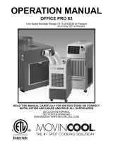
OPERATION MANUAL
CLASSIC PLUS 14 and CLASSIC PLUS 26
SERIAL NUMBER FROM FEBRUARY 1998 (0298) TO MARCH 2007 (0307)
READ THIS MANUAL CAREFULLY FOR INSTRUCTIONS ON CORRECT
INSTALLATION AND USAGE AND READ ALL SAFEGUARDS
SECCIÓN EN ESPAÑOL
SECTION EN FRANÇAIS
AVAILABLE AT WWW.MOVINCOOL.COM

LIMITED WARRANTY
DENSO SALES CALIFORNIA, INC. ("DENSO") warrants its MOVINCOOL
Products only to the extent stated in its official written warranties. Unless
otherwise specifically provided in writing by DENSO, DENSO warrants to end-
user that the Products shall be free of defects in materials or workmanship and will
function in accordance with DENSO's published specifications under ordinary in-
tended use and service for a period of twelve (12) months after delivery to the end-
user; provided, however, in the case of the compressor element of the Products
such warranty shall be for a period of thirty six (36) months after delivery to the
end-user. DENSO shall, at its sole option, repair or replace any defective Product
covered by this warranty. Such remedy shall be end-user's sole remedy with
respect to any particular defect in the Products.
This warranty does not cover defects or malfunctions which result from causes
beyond DENSO's control, including, without limitation, (i) unusual physical or
electrical stress; (ii) accident, neglect, abuse, misuse or other abnormal use; (iii)
failure to perform routine maintenance in accordance with DENSO'S recommended
procedures; (iv) normal wear and tear; (v) repairs or attempted repairs by an
unauthorized person; (vi) modifications or alterations to the Products; (vii) use with
supplies or devices not supplied or approved by DENSO; or (viii) improper
servicing. This warranty shall extend only to the original end-user and shall be void
if any labels or other identifying marks permanently affixed to Products when
shipped by DENSO are removed, altered, defaced or obliterated.
The aforesaid warranty is the only warranty made by DENSO with respect to the
Products and is in lieu of all obligations or liabilities on the part of DENSO for
damages arising out of or in connection with the sale, use or performance of the
Products, including, without limitation, any lost profits or any other consequential,
incidental, special or exemplary damages of any kind. DENSO DISCLAIMS ALL
OTHER WARRANTIES WITH REGARD TO THE PRODUCTS, INCLUDING ALL
IMPLIED WARRANTIES OF MERCHANTABILITY AND FITNESS FOR USE. THERE
ARE NO WARRANTIES WHICH EXTEND BEYOND THE DESCRIPTION CON-
TAINED HEREIN.
PURCHASE DATE: _____________________________________________________
SERIAL NUMBER: _____________________________________________________
DETACH HERE
© 2003 DENSO SALES CALIFORNIA, INC.
All rights reserved. This book may not be reproduced or copied, in
whole or in part, without the written permission of the publisher. DENSO
SALES CALIFORNIA, INC. reserves the right to make changes
without prior notice. MovinCool is a registerd trademark of
DENSO Corporation.

OPERATION MANUAL
CLASSIC PLUS 14 and CLASSIC PLUS 26

ii

iii
TABLE OF CONTENTS
FOREWORD ............................................................................................ 1
Definition of Terms .......................................................................... 1
GENERAL WARNINGS & CAUTIONS.................................................... 2
INVENTORY & ASSEMBLY .................................................................... 3
Inventory........................................................................................... 3
Assembly .......................................................................................... 4
INSTALLATION ....................................................................................... 5
Choosing and Installation Site ....................................................... 5
Moving the Unit................................................................................ 6
Plugging in the Unit ......................................................................... 7
FEATURES .............................................................................................. 8
OPERATION ............................................................................................ 9
Control Panel ................................................................................... 9
Operating in COOL Mode ............................................................. 10
Operating in Fan Only Mode ......................................................... 10
Changing from Fan Only Mode to COOL Mode .......................... 10
Operating Modes ...........................................................................11
Emptying the Drain Tank ............................................................... 12
DRAIN PUMP KIT (Optional)
(Classic Plus 14 model ONLY) ...................................................... 13
DRAIN PUMP KIT (Optional)
(Classic Plus 26 model ONLY) ...................................................... 14
DAILY INSPECTION & MAINTENANCE .............................................. 15
Emptying the Drain Tank ............................................................... 15
Cleaning the Air Filters.................................................................. 15
Filter Removal Method (both models) ......................................... 15
Filter Element Cleaning Method (both models) .......................... 15
IN-SEASON/OFF-SEASON INSPECTION &
MAINTENANCE .................................................................................... 16
In-Season ....................................................................................... 16
Off Season ...................................................................................... 16
TROUBLESHOOTING ........................................................................... 17
Self-Diagnostic Codes .................................................................. 17
TECHNICAL SPECIFICATIONS ........................................................... 18
SECCIÓN EN ESPAÑOL ................................................................ 19
SECTION EN FRANÇAIS ...............................................................41

iv

1
FOREWORD
Congratulations on purchasing the MovinCool portable air conditioner.
This manual explains how to assemble, install, operate, and maintain
the MovinCool Classic Plus 14 and Classic Plus 26 portable air condi-
tioning units. Please read this operation manual thoroughly to familiar-
ize yourself with the features of the unit and to ensure years of reliable
operation. You may also find it useful to keep this operation manual on
hand for reference.
Components and/or procedures are subject to change without prior
notice.
Definition of Terms
WARNING: Describes precautions that should be observed in
order to prevent injury to the user during installation or unit opera-
tion.
CAUTION: Describes precautions that should be observed in
order to prevent damage to the unit or its components, which may
occur during installation or unit operation if sufficient care is not
taken.
NOTE: Provides additional information that facilitates installation
or unit operation.

2
GENERAL WARNINGS & CAUTIONS
•All electrical work, if necessary, should only be performed by
qualified electrical personnel. Repair to electrical components by
non-certified technicians may result in personal injury and/or
damage to the unit. All electrical components replaced must be
genuine MovinCool parts, purchased from an authorized reseller.
•The proper electrical outlet for MovinCool units must be equipped
with a UL approved ground-fault breaker to prevent electrical shock
from the unit.
•Because of potential safety hazards under a certain condition, we
strongly recommend against the use of an extension cord. How-
ever, if you still elect to use an extension cord, it is absolutely
necessary that it will be a UL listed, 3-wire grounding type appli-
ance extension cord, having a 3-blade grounding plug and a 3-slot
receptacle that will plug into the appliance. The marked rating of
the extension cord should be 115 V, 15 A or equivalent.
•The Classic Plus 14 model is equipped with a ten (10) foot (3 meter)
power cord. The Classic Plus 26 model is equipped with a six (6)
foot (1.8 meter) power cord. If replacement, fixed location (hard
wired) or power cord lengthening (extension cord) cords are re-
quired, contact your reseller or a qualified electrician for approved
replacement methods.
•Never fold, or place heavy objects on the power cord. This could
result in damage to the power cord causing electrical shock or fire.
•Do not place water or any other liquid on the unit. This can cause
damage to the unit and increase the risk of electrical shock.
•Do not sit or stand on the unit.

3
INVENTORY & ASSEMBLY
Inventory
After unpacking your MovinCool unit, please check to make sure you
have the following items:
❏Classic Plus 14 or Classic Plus 26 MovinCool Unit (1)
❏Cool Air Outlet Ducts (2)
❏Screws (8)
❏Operation Manual/Warranty Card (1)
NOTE: If any of these items were not included in the box or appear
damaged, please contact your MovinCool reseller for replacement.
COOL AIR OUTLET DUCTS SCREWS
MOVINCOOL UNIT
OPERATION MANUAL/
WARRANTY CARD

4
INVENTORY & ASSEMBLY
Assembly
CAUTION: Before assembling
make sure the unit is on a flat, level
surface and the casters are in the
LOCKED position. (Both the Classic
Plus 14 and Classic Plus 26
MovinCool units have locking swivel
casters in the front only.)
Install each cool air outlet duct using 4 screws each as shown.
NOTE: Do not overtighten the screws when installing the cool air
outlet ducts. This could damage the base on the cool air outlet
duct assembly.
LOCKED
UNLOCKED
COOL AIR OUTLET
DUCT (2) SCREW (4 PER DUCT)

5
INSTALLATION
Choosing and Installation Site
CAUTION: Following are some precautions to consider before
choosing your installation site. Please review carefully as improper
installation may result in personal injury or damage to the unit.
•Do not use the unit in areas where leakage of flammable gas may
occur.
•Do not use the unit in areas where it will be exposed to rain or
water.
•Do not use the unit in an atmosphere of excessively corrosive gas
or vapor.
•Do not use in areas where the temperature is outside the allowable
operating range.
•Do not install the unit in sloping areas. The unit may move or topple
over even if the caster levers are set to LOCKED.
•Install the unit in areas that can withstand the weight of the unit.
The Classic Plus 14 unit weighs approximately 200 lbs (91 kg) and
the Classic Plus 26 unit weighs about 280 lbs (127 kg) (when the
drain tank is full of water).
•Allow 18 inches of unobstructed airflow for both air inlets and
outlets.
•Do not use the unit above 113˚F 50% RH.

6
INSTALLATION (cont.)
Moving the Unit
Unlock the casters and push the MovinCool unit from the front panel
edge to a flat, level surface and set the casters back to the LOCKED
position.
FRONT PANEL EDGE
LOCKED
UNLOCKED

7
INSTALLATION (cont.)
Plugging in the Unit
•Check the prongs and surface of the power cord plug for dust/dirt.
If dust and/or dirt are present, wipe off with a clean, dry cloth.
•Check the power cord, plug and prongs for damage or excess play.
If any damage or excess play is found, contact your MovinCool
reseller for repair.
•For the Classic Plus 26 model, fully insert plug into the A/C outlet
and rotate clockwise until it locks in place.
WARNING:
•If the power cord or plug is damaged, repair should only be
performed by qualified electrical personnel.
•Do not connect/disconnect the power cord or attempt to
operate buttons with wet hands. This could result in electrical
shock.
CAUTION:
•Classic Plus 14 model ONLY: The AC outlet (115 VAC Single
Phase, 60Hz) needs to be rated at 15A or higher. Do not share
the outlet with any other instrument or equipment.
•Classic Plus 26 model ONLY: The AC outlet (208/230 VAC Single
Phase, 60Hz) needs to be rated at 20A or higher. Do not share
outlet with any other instrument or equipment.
NOTE:
•Make sure the AC outlet is free of dirt, dust, oil, water, or any
other foreign matter.
•The Classic Plus 14 model is equipped with an approved NEMA
plug configuration (L5-15). the appropriate outlet must be used
for this plug type.
•The Classic Plus 26 model is equipped with an approved NEMA
plug configuration (L6-20). The appropriate outlet must be used
for this plug type.

8
FEATURES
Both models feature:
•An electronic control panel which allows the user to control the
unit’s operation easily.
•Dual fan speeds (either High or Low) in both COOL and Fan
Only modes.
•A digital display that indicates the temperature SET POINT (either
Fahrenheit or Celsius) in which the COOL Mode will operate. This
is also the local temperature the unit will try to maintain. The
Temperature Set Point can be adjusted by the SET TEMP buttons
(▼/▲).
•A condensate drain TANK FULL indicator display (LED).
•An automatic restart feature when the power is lost and regained.
The unit will return to the operating mode and temperature SET
POINT it was in prior to the loss of power.

9
OPERATION
Control Panel
Before operating the unit, it is important to familiarize yourself
with the basic controls located on the control panel.
➀COOL ON/OFF Activates/deactivates the COOL mode/
Button turns the unit off.
➁FAN ON/OFF Activates/deactivates the HIGH or LOW
Buttons fan mode.
➂SET TEMP Increases/decreases the temperature
Buttons (▼/▲)set point.
➃
TANK FULL LED Flashes when the drain tank is full.
➄SET POINT Indicates the current temperature set
Display point.
➅
Temperature Scale Illuminates to indicate the current
LED temperature being displayed is
either in °C or °F.
SET TEMP
FAN ON/OFF
COOL ON/OFF
Classic Plus

10
OPERATION (cont.)
Operating in COOL Mode
The unit can be operated in COOL mode by pressing the COOL
ON/OFF button (LED illuminates).
NOTE: In COOL mode the unit can only be turned off by pressing
the COOL ON/OFF button again, not by pressing the fan buttons.
➀Change the fan speed by pressing the HIGH or LOW fan buttons.
➁Change the temperature set point by pressing the SET TEMP
buttons (▼/▲).
NOTE: When turning the unit on, the temperature set point and fan
speed are determined by the last operating mode.
Operating in Fan Only Mode
➀The unit can also be operated in Fan Only mode by pressing either
the HIGH or LOW fan buttons (LED illuminates).
➁The unit can then be turned off by pressing the fan speed button
that is illuminated.
Changing from Fan Only Mode to COOL Mode
The COOL mode can be activated while the unit is operating in Fan
Only mode. To do this, simply press the COOL ON/OFF button (LED
illuminates).
NOTE: The Fan Only mode will not operate after the COOL mode
has been activated. After the COOL mode has been activated, the
unit cannot be turned off by pressing the fan buttons. The COOL
ON/OFF button must be pressed.

11
OPERATION (cont.)
Operating Modes
Both Classic Plus models operate in 2 modes, FAN Only and COOL.
When in FAN Only mode the unit circulates the surrounding air. When in
COOL mode, the compressor is engaged and cool air is circulated.
■COOL Mode
Both models will operate in FAN Only mode for approximately 120
seconds before the compressor engages (compressor time delay
program is 120 + 10 seconds).
■Temperature Control
The room temperature thermistor allows the unit to switch auto-
matically between COOL and FAN Only modes. This is dependent
upon inlet air temperature versus SET POINT temperature.
■Fan Mode Control DIP Switch
The Fan Mode Control DIP Switch determines whether the FAN will
continue to operate or stop when the compressor cycles off. (SET
POINT temperature equals inlet air or room temperature.) The unit
has been preset at the factory for continuous fan operation.
■Temperature Scale Display DIP Switch
The Temperature Scale Display DIP Switch changes the SET POINT
temperature that is displayed to either °C or °F. The unit has been
preset from the factory to display the SET POINT temperature in °F.
NOTE: If you wish to change the fan mode operation
(COOLOPERATE to COOLSTOP), and/or the Temperature Scale
Display (°F to °C), contact your MovinCool reseller.

12
OPERATION (cont.)
Emptying the Drain Tank
During COOL mode, condensate will accumulate in the drain tank.
When the drain tank becomes full, the FULL TANK LED will flash and
the unit will shut off automatically.
NOTE: If you want to empty the drain tank, while the unit is in
operation, press the COOL ON/OFF button to turn the unit off.
CAP
➁Remove the cap and empty the
drain tank.
➂Replace the cap and return the drain tank to the unit.
➃
Press the COOL ON/OFF or FAN ON/OFF button to restart the unit.
➀Pull the drain tank from the unit.

13
OPERATION (cont.)
DRAIN PUMP KIT (Optional)
(Classic Plus 14 model ONLY)
A drain pump kit (CPK-3) is available to allow continuous operation and
to eliminate the need for a drain tank.
•When the water collects to level
(A) in the pump reservoir, the
drain pump begins to operate
and discharge the water.
DISCHARGE HOSE
DRAIN PUMP
DRAIN PUMP
RESERVOIR
A
B
NOTE: The compressor will not operate while the drain pump is
discharging water.
•When the water level drops below level (B), the drain pump stops,
and the compressor will restart.
NOTE: If for any reason the water level exceeds that of level (A) in
the pump reservoir, an overflow Drain Switch will stop the com-
pressor operation.
NOTE: If the Fan Mode Control DIP Switch (see pg. 11) is set to the
STOP position, the entire unit (including fan operation) will turn off
whether due to the overflow Drain Switch or while the drain pump
is discharging water.

14
OPERATION (cont.)
DRAIN PUMP KIT (Optional)
(Classic Plus 26 model ONLY)
A drain pump kit (CPK-4) is available to allow continuous operation and
to eliminate the need for a drain tank.
•When the water collects to level
(A) in the pump reservoir, the
drain pump begins to operate
and discharge the water.
DISCHARGE HOSE
DRAIN PUMP
DRAIN PUMP
RESERVOIR
A
B
•When the water level drops below level (B), the drain pump stops,
and the compressor will restart.
NOTE: If for any reason the water level exceeds that of level (A) in
the pump reservoir, an overflow Drain Switch will stop the com-
pressor operation.
NOTE: If the Fan Mode Control DIP Switch (see pg. 11) is set to the
STOP position, the entire unit (including fan operation) will turn off
due to the overflow Drain Switch.
/