Page is loading ...

128-9351
1 of 16
Page 1
Model APS622E
Installation Manual
PATENTED: www.voxxintl.com/company/patents
Table Of Contents:
Before You Begin Page 2
Wire Harness Quick View Page 3
Installation Of The Major Components Page 4
6 Pin Power Harness Page 5
Door Lock / Unlock Harness Page 6 & 7
12 Pin Input/Output Harness Page 7 - 9
4 Pin Main Harness Page 9
Tachometer Programming Information Page 9 & 12
Transmitter Programming Information Page 10
Feature Bank 2 Program Information Page 10 & 11
Feature Bank 3 Program Information Page 12 & 13
Diagnostics Page 14
Data Bus Port Information Page 14
Completing The Installation Page 14
Circuit Wiring Diagram Page 16
FCC NOTICE
This device complies with part 15 of the FCC rules. Operation of this device is subject to the following
conditions:
(1) This device may not cause harmful interference, and
(2) This device must accept any interference received, including interference that may cause undesired
operation.
Caution: Changes or modications not expressly approved by the party responsible for compliance voids
the users authority to operate this device.

128-9351
2 of 16
Page 2
Before You Begin
PROFESSIONAL INSTALLATION IS
STRONGLY RECOMMENDED
Roll down window to avoid locking the keys in the vehicle
during installation.
Avoid mounting components or routing wires near hot surfaces
or near moving parts like the steering wheel as it may prevent
proper operation of the vehicle.
Tape or loom wires under the hood and dash for protection as
well appearance.
Use grommets when routing wires through metal surfaces to
prevent chang and shorting.
Use a Digital Multi Meter for testing and verifying circuits. DO
NOT USE A "TEST LIGHT" OR "COMPUTER SAFE PROBE"
as these can set off air bags or damage sensitive vehicle com-
puters and electronics.
For technical support go to
www.avxtech1.com
or call 1 800 225 6074
FCC COMPLIANCE
This device complies with Part 15 of the FCC rules and with RSS-210 of Industry Canada.
Operation is subject to the following two conditions:
1. This device may not cause harmful interference, and
2. This device must accept any interference received, including any interference that may
cause undesired operation.
Warning!
Changes or modications not expressly approved by the party responsible for
compliance could void the user’s authority to operate the equipment
NOTE: The manufacturer is not responsible for any radio or TV interference caused by unautho-
rized modications to this equipment. Such modications could void the user’s authority to
operate the equipment

128-9351
3 of 16
Page 3
PATENTED: www.voxxintl.com/company/patents
6 Pin Power Harness:
1124317
1 Blue Ignition 1 (+)
2 Red/White Battery 1 - 12V (+)
3 Green Ignition 2 (+)
4 Purple Accessory (+)
5 Red Battery 2 - 12V (+)
6 Yellow Starter Output
12 Pin Input/Output Harness:
1124321
1 Green/Orange Tachometer Input
2 Empty Cavity NA
3 Black/Blue Pulse Before Start
4 Black/LT. Green Pulse After Start
5 LT. Blue Ground While Running Output
6 DK. Blue (-) Trunk Release Output
7 Green/Yellow Glow Plug Input
8 Brown (+) Stop Input (Brake Sw.)
9 Gray (-) Negative Stop Input (Hood Sw.)
10 Black/Red Pulse After Shutdown
11 Black/Yellow Pulse During Crank
12 Black/White (-) Horn Output
4 Pin Main Harness:
1124320
1 Black Ground
2 White/Red Parking Light Relay Input
3 Yello/Black To Controlling Alarm’s Ign. Input
4 White Parking Light Relay Output
2 Pin Door Unlock Connector:
1122242
1 Red (-) Door Lock Output
2 Green (-) Door Unlock Output

128-9351
4 of 16
Page 4
This Remote Start System is designed to be used with
Automatic Transmission- Fuel Injection Vehicles Only!
INSTALLATION OF THE MAJOR COMPONENTS:
CONTROL MODULE: (P/N 1365445)
Select a mounting location inside the passenger compartment (up behind the dashboard).
The mounting location selected must be within 24” of the ignition switch wiring harness
to allow connection of the 6 pin main wiring harness.
Be certain that the chosen location will not interfere with proper operation of the vehicle.
Avoid mounting the module to or routing the wiring around the steering shaft/column,
as the module or wiring may wrap around or block the steering wheel preventing proper
control of the vehicle. Secure the module in the chosen location using cable ties or
screws as necessary.
Do Not Mount The Module In The Engine Compartment, as it is not waterproof.
THE RECEIVER/ANTENNA VALET SWITCH LED ASSEMBLY: (P/N 1181256)
The Superheterodyne Receiver Antenna Assembly which includes the LED and Valet/
Programming switch provided with this unit allows routing from below the dash board
for maximum operating range. Choose a location above the belt line (dashboard) of
the vehicle for best reception. Special considerations must be made for windshield
glass as some newer vehicles utilize a metallic shielded window glass that will inhibit
or restrict RF reception. In these vehicles, route the antenna toward a rear window
location for best reception. Secure the antenna with double stick tape provided. After
securing the antenna with tape, we advise also securing a section of the antenna cable
to a xed support. This will prevent the antenna from dropping down in case the double
stick tape is exposed to extreme heat which may loosen it’s gummed surface. Route
the connector toward the control module using caution not to pinch the cable as this
will cause poor or no RF reception to the control module. Connect the 5 pin cable to the
mating connector of control module.
HOOD PIN SWITCH: (P/N 1363699)
The pin switch included in this package are intended for protecting the hood area of
the vehicle. In all cases, the switch must be mounted to a grounded metal surface.
When the pin switch is activated, (hood/trunk open), it will supply a ground to the input
wire to inhibit the remote start function. In addition, the hood switch is required for the
safety shut down of the remote start unit. If the vehicle is being worked on, this hood
switch prevents the remote start activation even if the RF command to start is issued.
WARNING!: This switch must be installed in all applications. Failure to do so may
result in personal injury or property damage.
Mount the switch in the hood locations away from water drain paths. If necessary, a
bracket may be used to move the switch away from rain gutters or allow mounting to
the rewall behind the hood seal. In both cases the switch must be set up to allow the
hood to depress the switch at least 1/4 inch when the hood is closed and fully extended
when the hood is opened. For direct mounting, a 1/4 inch hole must be drilled. Care-
fully check behind the chosen location to insure the drill will not penetrate any existing
factory wiring or uid lines.
Drill a 1/4” hole in the desired location and thread the pin switch into it using a 7/16” nut
driver or deep well socket. If using the mounting bracket, rst secure the bracket to the
desired location and secure the pin switch in the pre-threaded mounting bracket hole.
DO NOT PLUG THE SIX PIN MAIN POWER HARNESS OR THE MULTI PIN INPUT
/ OUTPUT HARNESS INTO THE CONTROL MODULE UNTIL ALL CONNECTIONS
TO THE VEHICLE HAVE BEEN MADE. AFTER SELECTING YOUR TARGET WIRES
AS DEFINED BELOW, DISCONNECT THE NEGATIVE BATTERY CABLE FROM THE
VEHICLE BATTERY PRIOR TO MAKING ANY CONNECTIONS.
CAUTION: Do not remove the fuse holders from this wire harness. Fuses must
be used and located as close as possible to the power source for adequate pro-
tection of the vehicle.

128-9351
5 of 16
Page 5
WIRING THE 6 PIN MAIN POWER HARNESS Connector (P/N 1124317)
BLUE Wire: Ignition 1 Output
Connect this wire to the ignition 1 wire from the ignition switch. This wire will show +12
volts when the ignition key is turned to the “ON” or “RUN” and the “START” or CRANK”
positions, and will have 0 volts when the key is turned to the “OFF” and “ACCESSORY”
positions.
RED/WHITE TRACE WIRE: + 12 volt Battery 1 Source 20A Max
Locate the vehicle battery wire(s) at the ignition switch. Verication: These wires will
register voltage in all positions of the ignition switch. Connect the Red w/White wire to
the vehicle’s battery wire. This wire provides power for the control circuit as well as the
ignition 1 and ignition 2 relays.
GREEN Wire: Ignition 2 Output
Connect this wire to the ignition 2 wire from the ignition switch. This wire will show + 12
volts when the ignition key is turned to the “ON” or “RUN” position and is some cases
the “START” or CRANK” position. This wire will show 0 volts when the key is turned
to the “OFF” and “ACCESSORY” positions.
NOTE: See programming information (Bank 3 Selection # 7) concerning this wire to
allow output during the “START” mode
PURPLE Wire: Accessory Output
Connect this wire to the Accessory wire from the ignition switch. This wire will show +
12 volts when the ignition switch is turned to the “ACCESSORY” or “ON” and “RUN”
positions, and will show 0 volts when the key is turned to the “OFF” and “START” or
“CRANK” positions.
RED WIRE: + 12 Volt Battery 2 Source 30A Max
Locate the vehicle battery wire(s) at the ignition switch. Verication: These wires will
register voltage in all positions of the ignition switch. Connect the Red wire to the vehi-
cle’s battery wire. This wire provides power for the start relay and the accessory relay.
YELLOW Wire: Starter Output
Careful consideration for the connection of this wire must be made to prevent
the vehicle from starting while in gear. Understanding the difference between
a mechanical and an electrical Neutral Start Switch will allow you to properly
identify the circuit and select the correct installation method. In addition you
will realize why the connection of the safety wire is required for all mechanical
switch congurations.
WARNING! Failure to make this connection properly can result in personal injury and
property damage.
In all installations it is the responsibility of the installing technician to test the remote
start unit and ensure that the vehicle cannot start via RF control in any gear selection
other than park or neutral.
In both mechanical and electrical neutral start switch congurations, the connection of
the Starter wire will be made to the low current start solenoid wire of the ignition switch
harness. This wire will have +12 volts when the ignition switch is turned to the start
(crank) position only. This wire will have 0 volts in all other ignition switch positions
Wiring The 2 Pin Door Lock / Unlock Harness Connector (P/N 1122242
The Green Door Unlock output wires provide a pulsed ground output to control the vehicle door
unlock circuit. The Red Door lock output wires provide a pulsed ground output to control the
vehicle door lock circuit The output of these wire have a maximum switching capability of 250
mA. Many vehicles today have factory door lock relays which can be connected directly to these
output, however always conrm that the factory relays in your particular vehicle do not exceed the

128-9351
6 of 16
Page 6
Factory Lock Relay
Factory Unlock Relay
87a 87
30
85
86
87a 87
30
86
85
From Fuse Box + 12 Volts
LockUnlock
To Red Lock Wire
Of Control Module
To Green Unlock Wire
Of Control Module
rated 250mA output of the units door unlock/lock circuits. Plug the 2 pin connector of the
door unlock harness into the mating connector shell of the control module. Determine
the door lock and unlock circuit of the vehicle you are working on and wire according
to the diagrams shown.
3 Wire Negative Switched Door Lock Circuits:
In this application, The Green wire of the 2 pin harness provides a negative pulse
during the unlocking sequence. Connect the Green wire to the low current negative
signal wire from the factory door unlock switch to the factory door unlock relay.
Factory Lock Relay
Factory Unlock Relay
87a 87
30
85
86
87a 87
30
86
85
LockUnlock
When Using DLVI
X
Cut and Splice
Per the Install
Guide Instruction
Blue
When Using Relays
Factory Unlock Relay
87a 87
30
85
86
To Fused + 12 Volts
(+)
From Vehicle
Chassis Ground
Green NC
To Green Unlock Wire
Or PBS Wire Of Control Module
To Green Unlock Wire
Or PBS Wire Of Control Module
Positive Type Door Lock Circuits
Negative Type Door Lock Circuits
NOTE: Resistive Circuits, Multiplex Circuits As Well As 4 Wire Polarity Reversal
and 5 Wire Alternating 12 Volt Door Lock Control Circuits
These applications require the use of additional components which may include relays,
xed resistor, a door lock interface, or a data module. You can search the vehicle @
www.Flash-It.com for vehcile specic information, or contact our tech service line or
web site for additional information.

128-9351
7 of 16
Page 7
Wiring The 12 Pin Input / Output Harness, Connector (P/N 1124321
The auxiliary 12 pin connector provides low current outputs to control various functions
in the vehicle during different stages of the Remote Start unit’s operation. Understand-
ing these outputs and the time in which they occur will allow you to determine if they
are needed for the particular vehicle you are working on as well as how to use them.
1) Green/Orange: Tachometer Input Signal
This wire will continually monitor the engine’s tach rate while the unit is under power of
the Remote Start module. Route this wire to the vehicle ECM tach input or through the
rewall into the engine compartment and connect to the negative side of the ignition
coil. This Remote start unit learns the tach rate of the vehicle and in most cases will
operate properly from one multi coil unit pack regardless of the number of cylinders. If
the vehicle has a single coil for each cylinder, it may be necessary to connect to one of
the vehicle’s electronic fuel injector wires for proper RPM signal.
2) Empty Cavity, No Connection
3) Black/Blue: Pulsed Negative Output Before Start
The Blue/Black wire will provide a 1 second 250 mA pulsed negative output 1 second
before the remote start unit activates as well as when the transmitter is used to Unlock
the system. Typical use for this output would be to disarm a factory theft deterrent sys-
tem to prevent false triggering of the factory alarm when the remote start unit engages
or when the transmitter is used to unlock the doors.
NOTE: This output can be selected to operate like the door unlock output as set in alarm
feature setting #1 by selecting feature #17 of Bank 3 to “as feature1 Bank2”.
4) Black/LT. Green: Pulsed Ground Output After Start
The Black/LT Green wire will provide a 1 second 250 mA pulsed ground output after the
vehicle is started under control of the remote start unit. Typically this wire will be used
to re-lock the vehicle doors if the doors unlock automatically when the factory anti-theft
system is disarmed.
5) LT. Blue Wire: Ground Output While Running Under Remote Start Control
This wire provides a 250mA ground output that becomes active 2 seconds before
the Remote Start module initializes and remains grounded while the module is active
plus an additional 1 seconds after the system turns off. In all of the applications de-
scribed below, a relay will be required.
The LT. Blue wire can be used to accommodate the following situations:
A. Shock Sensor By Pass:
B. Additional Ignition Output:
C. GM VATS Key Override:
6) DK. Blue Wire: (-) Trunk Release Output
The Dark Blue wire supplies a 250mA ground pulsed output whenever channel three
of the receiver is accessed. Pressing the pre-programmed transmitter button for three
seconds will access channel three. This is a low current output and must be connected
to a relay to supply power to the trunk release or the circuit you wish to control. Con-
nect the Dark Blue wire to terminal # 86 of a 30 amp automotive relay Connect terminal
# 85 of the relay to a fused + 12 volt source. Connect the common, normally open,
and normally closed contacts of the relay to perform the selected function of channel 3.

128-9351
8 of 16
Page 8
7) Green w/ Yellow trace Wire: Diesel Wait To Start Input
The Green/Yellow wire, when connected to the wire that get + 12 volts during the glow
plug preheat stage will delay the starter output until this wire drops the 12 volts. In other
words, in a Diesel vehicle with glow plug preheat circuit, when the ignition is turned on,
the vehicle will not crank until the glow plugs are hot enough to re the atomized fuel oil
when injected into the cylinder. By connecting this wire to the glow plug + 12 volt wire,
when the remote start unit activates the ignition one output, the glow plug output also
activates. The remote start sees the green/yellow with positive voltage and waits for
this to go inactive( drop the 12 volts) before activating the starter motor. If this wire is
not used or you have difculty accessing the glow plug preheat circuit, you may elect
to utilize the Diesel timed output as specied in Remote Start feature selection Bank
3 Feature #11. NOTE: If green/yellow is used, it will override or negate any setting of
bank 3 feature #11.
8) Brown Wire: Brake Positive Inhibit Input
The Brown wire provides an instant shutdown for the Remote Start Control module
whenever it gets + 12 volts. If the Brake lights switch in the vehicle switches + 12 volts
to the brake light circuit, connect the Brown wire to the output side of the brake switch.
This will allow the Remote Start to shut down if an attempt is made to operate the vehicle
without the key while running under the control of the Remote Start. In most vehicles,
in order to shift into gear, the brake pedal must be depressed. The brake input will in
turn cause the remote start unit to shut off.
9) Gray Wire: Negative Inhibit Input
The Gray wire provides an instant shutdown for the Remote Start Control Module when-
ever it is grounded. Connect the gray wire to the hood pin switch previously installed.
This wire must be routed through a grommet in the rewall and connected to the hood
pin switch. If the pin switch is to be used with an alarm system, connect this wire using
a diode assembly.
MPORTANT! DO NOT RELEASE THIS VEHICLE TO THE CONSUMER UNTIL
YOU CONFIRM THE OPERATION OF THE HOOD PIN SAFETY SHUT DOWN
FEATURE.
WARNING! This connection is a safety wire and must be connected to a hood pin switch
and tested as described. Failure to do so may result in personal injury or property dam-
age. This wire may also be used if the vehicle brake light circuit switches ground to the
brake lights. An isolation diode must be used for ground switched brake light circuits
and must be connected to the output of the brake switch.
To test this circuit, while the vehicle is running under control of the remote start unit,
open the vehicle’s hood. The remote start unit should shut down immediately. If not,
check the wiring to the control module and the under hood pin switch.
DO NOT RELEASE THE VEHICLE TO THE CONSUMER IF THIS CIRCUIT DOES
NOT PERFORM AS SPECIFIED.
10) Black/Red Wire: Pulsed Ground Output After Shutdown
The Black/Red wire will provide a 1 second 250 mA pulsed ground output after the remote
start unit shuts down and the G.W.R. O/P turns off. This output will occur regardless
of whether the circuit times out or is manually terminated. Typically this output will be
used to re-lock the vehicle doors if the doors unlock automatically when the ignition
circuit transitions to off.
11) Black/Yellow Trace Wire: Ground Output During Start (Crank)
The Black/Yellow wire will provide a 250 mA ground output while the starter output of
the remote start unit is active. This output can be used to activate the Crank Low/Bulb
Test wire found in some GM vehicles. This wire is also referred to as the ECM wake
up wire in some Chrysler vehicles.

128-9351
9 of 16
Page 9
12 Black/White Wire: (-) Horn Output
The black w/ white trace wire is provided to beep the vehicle’s horn. This is a transistor-
ized low current output, and should only be connected to the low current ground output
from the vehicle’s horn switch.
If the vehicle uses a + 12 VDC horn switch, then connect the black w/ white trace wire
to terminal 86 of a 30Amp automotive relay, and connect relay terminal 85 to a fused
+ 12 VDC battery source. Connect relay terminal 87 to the vehicle’s horn switch output,
and connect relay terminal 30 to a fused + 12 VDC battery source
NOTE: The outputs above are low current outputs and must be used with a relay if the
circuit’s requirement is more than 250 mA.
4 Pin Main Harness, Connector (P/N 1124320)
1) Black Wire: Chassis Ground
Connect the Black wire to a known vehicle ground source or to a solid clean metal part
of the chassis. Be certain to remove any paint or grease and secure this wire with a
self tapping screw and ring terminal.
2) White w/ Red trace Wire: Parking Light Relay Input Wire
This wire is the common contact of the on board parking light asher relay. If the vehicle
you are working on has +12 volt switched parking lights, connect this wire to a fused +
12 volt source. (Max. 15 Amps)
NOTE: If the vehicle’s parking lights are ground switched, connect this wire to chassis
ground.
3) Yellow w/ Black trace Wire: (+) Output To Alarm Ignition Input
This is the positive output that will connect to an alarm system allowing the alarm to
operate while under control of the remote start. This wire can connect to an existing
alarm system, or if available to the factory alarms ignition input.
4 White Wire: Parking Light Relay Output
This wire is the normally open contact of the on board parking light ash relay. Connect
this wire to the vehicle’s parking light feed wire. This is the wire that gets switched on,
either (+) or (-), when the vehicle’s parking light switch is activated.
5 Wire Antenna Receiver Connector (P/N 1124318)
Connect the mating end of the previously mounted receiver harness to the mating
connector on the module. This harness will be the supply for the LED, Valet Switch as
well as the RX & 5VDC of the receiver.
Programming Tach Rate:
NOTE: All applications require that tach be programmed.
The unit will not operate unless tach is programmed. If an attempt is made to
start the vehicle via the remote start without rst programming tach, the unit
will ash the parking lights 7 times indicating tach has not been learned and
stored. If the tach rate is not properly programmed for the specic vehicle, the
unit may not realize that the vehicle is running and in certain instances re-en-
gage the starter motor.
The Remote Start Unit will learn the tach rate of most vehicle’s single coil, multiple coil
packs, or single injector.

128-9351
10 of 16
Page 10
To learn tach:
1. Turn the ignition key to the On position.
2. Press and release the valet/program push button switch 3 times.
3. Immediately turn the ignition key Off.
4. Press and hold the valet/program push button switch, then start the vehicle using
the key.
5. When the unit senses the tach signal, the parking lights will begin to ash.
6. Wait for at least 5 ashes
7. Release the valet/program switch. The parking lights come on for three seconds
to indicate that the learned tachometer signal is stored and the unit is out of the
tachometer learn mode.
NOTE: If the unit fails to learn tach rate due to an improper tachometer connection or
a poor tach source, the parking lights will not ash. To correct this situation,
locate and connect the Green/Orange wire to the proper tach signal, and then
repeat the tach learn routine.
PROGRAMMING BANK 1 (TRANSMITTERS):
1) Turn the ignition key to the on position.
2) Press and release the valet/programming switch 3 times (Siren Chirps Once).
3 Press the Button of each transmitter you want programmed until the parking lights ash.
4) Turn the ignition switch off to exit the programming mode.
PROGRAMMING BANK 2 (ALARM FEATURES):
You can enter bank 2 from bank 1 by turning the ignition key off then on from step 4 of
Bank 1, the lights will ash twice, or You can also go right to bank 2 by:
1) Turn the ignition key to the On position.
2) Press and release the valet/programming switch 3 times (Lights Flash Once).
3) Turn the ignition key off then on.
4) Press the pushbutton switch once to advance to feature 1, twice to advance to feature
2, etc, then use the button of the transmitter to select the feature setting.
Example to set passive arming:
1) Turn the ignition key to the on position.
2) Press and release the valet/programming switch 3 times
3) Turn the ignition key off, then on.
4) Press the pushbutton switch once to advance to features 1, door unlock output timing
then use the button of the transmitter to select your desired setting.
5) To exit the programming mode, turn the ignition key off. The parking lights ash
upon exit

128-9351
11 of 16
Page 11
SELECTABLE FEATURES
The selectable features of this unit can be set manually as explained on the previous page.
Factory default settings are indicated by BOLD text below.
NOTE: Manual programming Keyless Entry Models with no horn output will Flash the Parking Lights instead of chirp where chirp is indicated.
Also, no data will be indicated if a feature is not available for a particular model. The unit will enter the feature but no selection will be available.
Feature Selection 1 Chirp 2 Chirps 3 Chirps 4 Chirps 5 Chirps 6 Chirps
1st DoorL/UL 1S/1S 3.5/3.5 Sec. 1S L, Dbl. U/L Dbl L, 1S UL Dbl L, Dbl UL 1S/350mS ul
2nd Accy Lock Not Available
3rd Accy. UL Not Available
4th Headlights Not Available
5th Passive Locks Not Available
6th Pass/Act Arm Not Available
7th Siren/Horn Not Available
8th Horn Chirp 10mS 16mS 30mS 40mS 50mS
9th O/R Method Not Available
10th 2 Step U/L Not Available
11th Chp Del Tx On Off
12th Trigger Circuits Not Available
13th L/UL Poll Not Available
14th Aux Ch 5 Sel Not Available
15th Aux Ch 6 Sel Not Available
16th Aux Ch 7 Sel Not Available
17th Trigger Delay Not Available
18th DBI/ADS Select Not Available

128-9351
12 of 16
Page 12
PROGRAMMING BANK 3 (REMOTE START ):
You can enter Bank 3 from Bank 2 by turning the ignition key off then on after you've
made the changes you wanted in Bank 2, (Siren two Long Chirp). You can also go right
to bank 3 by:
1) Turn the ignition key to the On position.
2) Press and release the valet/programming switch 3 times (Siren Chirps).
3) Turn the ignition key off then on. (Siren Short Then long Chirp)
4) Turn the ignition key off then on. (Siren two Long Chirp)
5) Press the push button switch once to advance to feature 1, twice to advance to fea-
ture 2, etc,,,then use the lock button of the transmitter to select the feature setting.
Example to set engine input check to DBI Tach:
1) Turn the ignition key to the On position.
2) Press and release the valet/programming switch 3 times (Siren Chirps).
3) Turn the ignition key off then on. (Siren Short Then long Chirp)
4) Turn the ignition key off then on. (Siren two Long Chirp)
5) Press the pushbutton switch ve times to advance to features 5, Input Check, then
use the lock button of the transmitter to select three chirps, "DBI Tach"
6) To exit the programming mode, turn the ignition key off. The program mode is auto-
matically exited when there is no activity on the pushbutton switch or the transmitter
lock button.
TACH RATE PROGRAMMING:
1. Turn the ignition key to the On position.
2. Press and release the valet/program push button switch 3 times.
3. Immediately turn the ignition key Off.
4. Press and hold the valet/program push button switch, then start the vehicle using
the key.
5. When the unit senses the tach signal, the parking lights will begin to ash.
6. Allow at least 5 ashes then release the valet/program pushbutton switch. The parking
lights will turn on for three seconds to indicate that the learned tach signal is stored
and the unit is out of the tach learn mode.
NOTE: If the unit fails to learn tach rate due to an improper tachometer connection or
a poor tach source, the parking lights will not ash. To correct this situation,
locate and connect the Green/Orange wire to the proper tach signal, and then
repeat the tach learn routine.

128-9351
13 of 16
Page 13
RF Programmable Features Bank 3 Is Remote Start Selectable Features:
Feature Selection 1 Chirp 2 Chirps 3 Chirps 4 Chirps 5 Chirps 6 Chirps
1st Defrost Output Not Available
2nd RF Start Chirp Off On On & Car Finder
3rd Run Time 5 Mins 10 Mins 15 Mins 20 Mins 45 Mins 60 Mins
4th Parking Lights On Steady Flashing
5th Input Check Voltage Tach DBI Tach Hybrid
6th Voltage Level >0.5V B4 Start < 0.5V B4 Start
7th Ign. 2 Select Off During Crank On During Crank Same As Accy.
8th Ign. 3 Select Not Available
9th Diagnostics Off On
10th Crank Time 0.8 Sec 1.0 Sec 1.5 Sec 2.0 Sec
11th Gas/Diesel Gas Diesel 10 Diesel 15 Diesel 20
12th Transponder O/P Not Available
13th Temp Start Not Available
14th Crank Averaging Averaging Preset Time
Note: When averaging, the engine must be started 4 times with the key to be effective.
15th R/S Shock Not Available
16th Turbo Select Not Available
17th Black/Blue (Aux O/P) Single Pulse As Feat 1 Bank 2
18th One or Two Press Start Two Press One Press
NOTE : When feature #5 is set for Voltage or Hybrid, the unit must also have feature #14 set for Averaging or the unit will ash the Pk. Lts. 7 times and
not start.
When using the RF programmer, enter the program mode as follows:
Turn the ignition on
Press and release valet switch 3 times
Turn ignition off then on
Press and hold valet switch for 5 seconds
Siren chirps 2 times indicating access to RF feature program mode.

128-9351
14 of 16
Page 14
Diagnostics:
Enter Bank 3 and turn on selectable feature # 9 as described in the feature selection
and setting section.
Exit the feature selection mode then press and hold the pushbutton valet/program switch
and then turn the ignition switch to the on position.
NOTE: Diagnostic mode is a temporary mode. Once you have accessed the diagnostic
mode, the unit will pause for two seconds then begin to ash the last stored
shut down code. This code will be displayed three times in succession, then
the unit will automatically exit the diagnostic mode.
The parking lights will ash a number of times indicating the reason for the last remote
start shutdown. The light ash indications are as follows:
1 Flash Run timer expired
2 Flashes Low or no tach signal (RPM)
3 Flashes Positive inhibit wire activation
5 Flashes RF shutdown signal received, or manual start trigger wire reactivated.
6 Flashes High tach signal (RPM)
7 Flashes Tach signal has not been learned
8 Flashes Negative inhibit wire activation
4 PIN DATA BUS PORT (DBI Port)
The 4 pin port located on the side of this module is for proprietary Audiovox data bus
interface modules. These modules are used to access a variety of features in the vehicle
which can be as simple as door trigger inputs, to more complex door lock outputs, or
transponder interfaces for remote starting. DO NOT connect anything to this port other
than the Audiovox DBI interface modules or damage to the Remote Start will occur. All
installation instructions for the DBI modules will be packaged with the individual com-
ponent along with the proper 4 pin wiring harness requires to access the data transmit
& receive as well as the proper voltage levels for the interface.
COMPLETING THE INSTALLATION:
After you have conrmed the operation of the Remote Start unit and tested all the safety
features of the system:
1. Mount the control module up and behind the dash securing it in place with cable
ties or screws. Be certain that the chosen mounting location will not inhibit any of
the controls of the vehicle.
2. Securely harness and tie all wiring up and away from all hot and moving parts that they
may come in contact with under the dash board or in the engine compartment areas.
CAUTION: Particularly avoid the area around the steering shaft and column, as wires
can wrap around these mechanisms and impair the safe operation of the
vehicle.
3. Apply the Caution Labels supplied with this kit to a conspicuous area in the engine
compartment. Make sure to clean the surface before afxing the label.
4. Check the vehicle’s wipers, lights, horn, etc, to insure proper operation.
5. Replace all panels that were removed during installation, and retest the system.
6. Explain all activated features and safety systems associated with Remote Start Unit
installed to the customer.

128-9351
15 of 16
Page 15
NOTES

128-9351
16 of 16
Page 16
© 2014 Voxx Electronics Corporation, 150 Marcus Blvd. Hauppauge, NY 11788 128-9351
For technical support go to www.prestigecarsecurity.com or call 1 800 225 6074
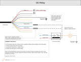
APS622E
Wire Side View Of Connector
1 Blue (Ign 1)
2 Red/White (+ 12VDC Relays Ign 1 & Ign 2)
3 Green (Ign 2)
4 Purple (Accessory)
5 Red (+ 12VDC Relays ACC & Start)
6 Yellow (Starter)
Connect Data Module
DBI Protocol
To Mating Connector
Push Button
LED Transceiver
500mA
MAX
(-) Lock Output
(-) Unlock Output
Green
Red
Yellow/Black (To controlling Alarm’s Ign Input)
White (Parking Light Relay Output)
Black (Chassis Ground)
White/Red (Parking Light Relay Input)
123
456
1 Green/Orange Tach Input
3 Black/Blue (-) Pulse Before Start Output
4 Black/LT.Green (-) Pulse After Start Output
5 LT. Blue Ground Out While Running
7 Green/Yellow Glow Plug Input
8 Brown (+) Inhibit Wire Brake Input
9 Gray (-) Negative Inhibit Wire Hood Pin
10 Black/Red (-) Pulse After Shut Down Output
11 Black/Yellow (-)Pulse During Crank Output
2 Empty Cavity No Connection
6 DK. Blue (-) Trunk Release Output
12 Black/White (-) Horn Output
Blue (LED -)
Grey (Valet)
Black (-)
Green (RX)
Red (+)
/