
POWER PROTECTION
UPStation GXT 2U™
USER MANUAL
700-3000VA
120V


i
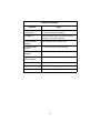
TABLE OF CONTENTS
IMPORTANT SAFETY INSTRUCTIONS. . . . . . . . . . . . . . . . . . . . . 1
GLOSSARY OF SYMBOLS . . . . . . . . . . . . . . . . . . . . . . . . . . . . 3
INTRODUCTION . . . . . . . . . . . . . . . . . . . . . . . . . . . . . . . . . . . . 4
MAJOR COMPONENTS. . . . . . . . . . . . . . . . . . . . . . . . . . . . . . . 5
Transient Voltage Surge Suppression (TVSS) and EMI/RFI Filters . . . 5
Rectifier/Power Factor Correction (PFC) Circuit . . . . . . . . . . . . . . . . . . 5
Inverter. . . . . . . . . . . . . . . . . . . . . . . . . . . . . . . . . . . . . . . . . . . . . . . . . . 5
Battery Charger . . . . . . . . . . . . . . . . . . . . . . . . . . . . . . . . . . . . . . . . . . . 6
DC to DC Converter. . . . . . . . . . . . . . . . . . . . . . . . . . . . . . . . . . . . . . . . 6
Battery . . . . . . . . . . . . . . . . . . . . . . . . . . . . . . . . . . . . . . . . . . . . . . . . . . 6
Dynamic Bypass . . . . . . . . . . . . . . . . . . . . . . . . . . . . . . . . . . . . . . . . . . 6
GXT 2U (Rear View) . . . . . . . . . . . . . . . . . . . . . . . . . . . . . . . . . . . . . . . 7
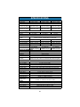
INSTALLATION . . . . . . . . . . . . . . . . . . . . . . . . . . . . . . . . . . . . 8
Preparation . . . . . . . . . . . . . . . . . . . . . . . . . . . . . . . . . . . . . . . . . . . . . . 8
Tower UPS Installation . . . . . . . . . . . . . . . . . . . . . . . . . . . . . . . . . . . . . 8
Rack-Mount UPS Conversion and Installation. . . . . . . . . . . . . . . . . . . . 9
External Battery Cabinet Installation . . . . . . . . . . . . . . . . . . . . . . . . . . 12
CONTROLS AND INDICATORS. . . . . . . . . . . . . . . . . . . . . . . . . 13
ON/Alarm Silence/Manual Battery Test Button . . . . . . . . . . . . . . . . . . 13
Standby/Manual Bypass Button . . . . . . . . . . . . . . . . . . . . . . . . . . . . . 14
Load/Battery Level Indicators (4 Green, 1 Amber) . . . . . . . . . . . . . . . 14
Fault Indicator LED (Red) . . . . . . . . . . . . . . . . . . . . . . . . . . . . . . . . . . 14
Bypass Indicator LED (Amber) . . . . . . . . . . . . . . . . . . . . . . . . . . . . . . 14
UPS ON Indicator LED (Green) . . . . . . . . . . . . . . . . . . . . . . . . . . . . . . 14
Battery Indicator LED (Amber). . . . . . . . . . . . . . . . . . . . . . . . . . . . . . . 14
AC Input Indicator LED (Green). . . . . . . . . . . . . . . . . . . . . . . . . . . . . . 14
Output Voltage Selection . . . . . . . . . . . . . . . . . . . . . . . . . . . . . . . . . . . 15
OPERATING INSTRUCTIONS . . . . . . . . . . . . . . . . . . . . . . . . . . 16
Normal Mode Operation. . . . . . . . . . . . . . . . . . . . . . . . . . . . . . . . . . . . 16
Battery Mode Operation. . . . . . . . . . . . . . . . . . . . . . . . . . . . . . . . . . . . 16
Battery Recharge Mode . . . . . . . . . . . . . . . . . . . . . . . . . . . . . . . . . . . . 16

ii
COMMUNICATIONS . . . . . . . . . . . . . . . . . . . . . . . . . . . . . . . . 17
Communications Interface Port . . . . . . . . . . . . . . . . . . . . . . . . . . . . . . 17
Pin 4 - Remote Shutdown on Battery. . . . . . . . . . . . . . . . . . . . . . . . . . 17
UPS Intelligent Communications . . . . . . . . . . . . . . . . . . . . . . . . . . . . . 18
CONFIGURATION PROGRAM . . . . . . . . . . . . . . . . . . . . . . . . . 19
GXT 2U Configuration Program Abilities . . . . . . . . . . . . . . . . . . . . . . . 19
What You Will Need . . . . . . . . . . . . . . . . . . . . . . . . . . . . . . . . . . . . . . . . . . . 19
MAINTENANCE . . . . . . . . . . . . . . . . . . . . . . . . . . . . . . . . . . . 20
Battery Replacement . . . . . . . . . . . . . . . . . . . . . . . . . . . . . . . . . . . . . . 20
Internal Battery Replacement Procedures: . . . . . . . . . . . . . . . . . . . . . . . . . . 21
Fuse Replacement. . . . . . . . . . . . . . . . . . . . . . . . . . . . . . . . . . . . . . . . 22
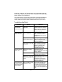
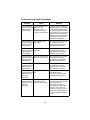
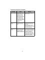
TROUBLESHOOTING . . . . . . . . . . . . . . . . . . . . . . . . . . . . . . . 23
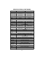
SPECIFICATIONS . . . . . . . . . . . . . . . . . . . . . . . . . . . . . . . . . . 28
BATTERY CABINET SPECIFICATIONS . . . . . . . . . . . . . . . . . . . 30
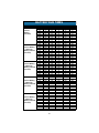
BATTERY RUN TIMES . . . . . . . . . . . . . . . . . . . . . . . . . . . . . . 31

1
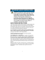
IMPORTANT SAFETY INSTRUCTIONS
SAVE THESE INSTRUCTIONS
This manual contains important safety instructions. Read all safety, instal-
lation, and operating instructions before operating the Uninterruptible
Power System (UPS). Adhere to all warnings on the unit and in this man-
ual. Follow all operating and user instructions. Individuals without previ-
ous training can install and operate this equipment.
It is not intended for use with life support and other designated “critical”
devices. Maximum load must not exceed that shown on the UPS rating
label. The UPS is designed for data processing equipment. If uncertain,
consult your local dealer or Liebert representative.
This UPS is designed for use on a properly grounded (earthed),
100-127 VAC, 50 Hz or 60 Hz supply.
ELECTROMAGNETIC COMPATIBILITY—The GXT 2U
™
Series com-
plies with the limits for a CLASS A DIGITAL DEVICE, PURSUANT TO
Part 15 of FCC rules. Operation is subject to the following two conditions:
(1) This device may not cause harmful interference, and (2) this device
must accept any interference received, including interference that may
cause undesired operation. Operating this device in a residential area is
likely to cause harmful interference that users must correct at their own
expense.
Operate the UPS in an indoor environment only in an ambient tempera-
ture range of 32°F to +104°F (0°C to +40°C). Install it in a clean environ-
ment, free from moisture, flammable liquids, gases and corrosive
substances.
!
WARNING
OPENING OR REMOVING THE COVER MAY EXPOSE
YOU TO LETHAL VOLTAGES WITHIN THIS UNIT
EVEN WHEN IT IS APPARENTLY NOT OPERATING
AND THE INPUT WIRING IS DISCONNECTED FROM
THE ELECTRICAL SOURCE. OBSERVE ALL
CAUTIONS AND WARNINGS IN THIS MANUAL.
FAILURE TO DO SO MAY RESULT IN SERIOUS
INJURY OR DEATH. REFER ALL UPS AND BATTERY
SERVICE TO QUALIFIED SERVICE PERSONNEL. DO
NOT ATTEMPT TO SERVICE THIS PRODUCT
YOURSELF. NEVER WORK ALONE.

2
This UPS contains no user serviceable parts except the internal battery
packs and the rear input line fuses. The UPS ON/Standby push buttons
do not electrically isolate internal parts. Under no circumstances attempt
to gain access internally other than to replace the batteries due to risk of
electric shock or burn. Do not continue to use the UPS if the front panel
indications are not in accordance with these operating instructions or if
the UPS performance alters in use. Refer all faults to your local dealer,
Liebert representative or the Liebert Worldwide Support Group.
Servicing of batteries should be performed or supervised by personnel
knowledgeable of batteries and the required precautions. Keep unautho-
rized personnel away from the batteries. PROPER DISPOSAL OF BAT-
TERIES IS REQUIRED. REFER TO YOUR LOCAL LAWS AND
REGULATIONS FOR BATTERY DISPOSAL REQUIREMENTS.
Never block or insert any object into the ventilation holes or other open-
ings of the UPS.
DO NOT CONNECT equipment that could overload the UPS or demand
DC current from the UPS, for example: electric drills, vacuum cleaners,
laser printers, hair dryers or any appliance using half-wave rectification.
Storing magnetic media on top of the UPS may result in data loss or cor-
ruption.
Turn the UPS off and isolate the UPS before cleaning; use only a soft
cloth, never liquid or aerosol cleaners. Keep the front and rear vents free
of dust accumulation that could restrict airflow.
When replacing batteries, replace with the same Liebert authorized
replacement battery kits.
!
CAUTION
Do not dispose of battery or batteries in a fire. The
battery may explode.
Do not open or mutilate the battery or batteries.
Released electrolyte is harmful to skin and eyes. It
may be toxic.
!
CAUTION
A battery can present a risk of electrical shock and
high short circuit current. The following precautions
should be observed when working on batteries:
• Remove watches, rings, or other metal objects.
• Use tools with insulated handles.

3
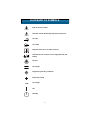
GLOSSARY OF SYMBOLS
•
Risk of electrical shock
Indicates caution followed by important instructions
AC input
AC output
Requests the user to consult the manual
Indicates the unit contains a valve-regulated lead acid
battery
Recycle
DC voltage
Equipment grounding conductor
Bonded to ground
AC voltage
ON
Standby
i

4
INTRODUCTION
Congratulations on your choice of the Liebert UPStation GXT 2U
™
Unin-
terruptible Power System (UPS). It provides conditioned power to micro-
computers and other sensitive electronic equipment.
Upon generation, AC power is clean and stable. However, during trans-
mission and distribution it may be subject to voltage sags, spikes, or com-
plete power failure that may interrupt computer operations, cause data
loss, or even damage equipment. The UPStation GXT 2U protects equip-
ment from these disturbances.
The UPStation GXT 2U comes in nominal power ratings of 700, 1000,
1500, 2000 and 3000 VA. Complete model specifications appear at the
end of this manual.
The UPStation GXT 2U is a compact, “on-line” UPS. An on-line UPS con-
tinuously conditions and regulates its output voltage, whether utility power
is present or not. It supplies connected equipment with clean sinewave
power. Sensitive electronic equipment operates best from sinewave
power.
For ease of use, the UPStation GXT 2U features a light-emitting diode
(LED) display to indicate either load percentage or battery capacity
depending upon the mode of operation. It also provides self-diagnostic
tests, a combination On/Alarm Silence/Manual Battery Test button, a
Standby button, user configurable program, and two levels of alarms
when the unit is operating on battery.
The UPStation GXT 2U has an interface port for communication between
the UPS and a network server or other computer systems. This port pro-
vides detailed operating information including voltages, currents, and
alarm status to the host system when used in conjunction with Liebert
MultiLink
™
software. MultiLink software can also remotely control UPS
operation.

5
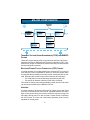
MAJOR COMPONENTS
TRANSIENT VOLTAGE SURGE SUPPRESSION (TVSS) AND EMI/RFI
FILTERS
These UPS components provide surge protection and filter both electro-
magnetic interference (EMI) and radio frequency interference (RFI). They
minimize any surges or interference present in the utility line and keep the
sensitive equipment protected.
RECTIFIER/POWER FACTOR CORRECTION (PFC) CIRCUIT
In normal operation, the rectifier/power factor correction (PFC) circuit con-
verts utility AC power to regulated DC power for use by the inverter while
ensuring that the waveshape of the input current used by the UPS is near
ideal. Extracting this sinewave input current achieves two objectives:
• The utility power is used as efficiently as possible by the UPS
• The amount of distortion reflected on the utility is reduced
This results in cleaner power being available to other devices in the build-
ing not being protected by the UPStation GXT 2U.
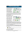
INVERTER
In normal operation, the inverter utilizes the DC output of the power factor
correction circuit and inverts it into precise, regulated sinewave AC power.
Upon a utility power failure, the inverter receives its required energy from
the battery through the DC to DC converter. In both modes of operation,
the UPS inverter is on-line and continuously generating clean, precise,
regulated AC output power.
Input Output
Inverter
Battery
Battery
Charger
DC to DC
Converter
Rectifier
/PFC
TVSS &
EMI/RFI
Filters
L
N
G
L
N
G
Dynamic
Bypass

6
BATTERY CHARGER
The battery charger utilizes energy from the utility power and precisely
regulates it to continuously “float charge” the batteries. The batteries are
being charged whenever the UPStation GXT 2U is plugged in, even when
the UPS is not turned on.
DC TO DC CONVERTER
The DC to DC converter utilizes energy from the battery system and
raises the DC voltage to the optimum operating voltage for the inverter.
This allows the inverter to operate continuously at its optimum efficiency
and voltage, thus increasing reliability.
BATTERY
The UPStation GXT 2U utilizes valve-regulated, nonspillable, flame retar-
dant, lead acid batteries. To maintain battery design life, operate the UPS
in an ambient temperature of 68°F to 77°F (20°C to 25°C). Optional exter-
nal battery cabinets are available to extend battery run times.
DYNAMIC BYPASS
The UPStation GXT 2U provides an alternate path for utility power to the
connected load in the unlikely event of a UPS malfunction. Should the
UPS have an overload, overtemperature, or UPS failure condition, the
UPS automatically transfers the connected load to bypass. Bypass opera-
tion is indicated by an alarm and illuminated Bypass LED (other LEDs
may be illuminated to indicate the diagnosed problem). To manually trans-
fer the connected load from the inverter to bypass, press the Standby but-
ton once.
NOTE
The bypass power path does NOT protect the connected
equipment from disturbances on the utility supply.

7
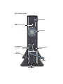
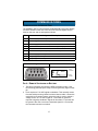
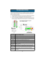
GXT 2U (REAR VIEW)
Input Fuse/Circuit
Breaker
AC Input
Support Base
Output
Receptacles
External Battery
Connector
Cooling Fan
Intellislot Port
DB-9
Communications Port

8
INSTALLATION
PREPARATION
1. Visually inspect the UPS for freight damage. Report damage to the
carrier and your local dealer or Liebert representative.
2. Decide where to place the GXT 2U. Install the UPS indoors in a con-
trolled environment, where it cannot be accidentally turned off. Place
it in an area of unrestricted airflow around the unit, away from water,
flammable liquids, gases, corrosives, and conductive contaminants.
Maintain a minimum clearance of 4 inches (100mm) in the front and
rear of the UPS. Maintain an ambient temperature range of 32°F to
104°F (0°C to 40°C).
3. The GXT 2U may be installed in either a tower configuration or in a
rack, depending on available space and use considerations. Deter-
mine the type of installation and follow the appropriate instructions in
either Tower UPS Installation or Rack-Mount UPS Conversion
and Installation.
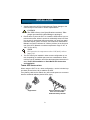
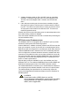
TOWER UPS INSTALLATION
When using the GXT 2U in a tower configuration, use the included sup-
port base (shown below, left) to stabilize the UPS.
If any battery cabinets are added, they will include spacers to accommo-
date the additional cabinets (shown below, right).
!
CAUTION
The UPS is heavy (see Specifications section). Take
proper precautions when lifting or moving it.
NOTE
UPS operation in temperatures above 77°F (25°C) reduces
battery life.
Support base Spacers added to support
base to accommodate
additional battery cabinets

9
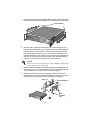
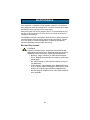
RACK-MOUNT UPS CONVERSION AND INSTALLATION
1. For slide rail installations, first remove the top/side fin. Slide the
top/side fin forward, then lift it up to remove. If desired, install the
optional rack mount handles that were shipped with the UPS.
Securing hardware and slide rails are sold separately. Contact your
local dealer or Liebert representative for these additional options and
any assistance needed.
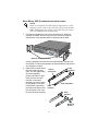
2. Unpack the two slide assem-
blies and mounting hard-
ware. The slide assemblies
are interchangeable
between left-hand or right-
hand. Remove the inner
member of each slide
assembly (as seen at right)
by extending it to its outer-
most position, depressing
the locking mechanism and
then pulling the inner mem-
ber from the slide assembly.
NOTE
When rack mounted, the UPS must be supported by a shelf,
brackets or slide rails on each side. The rack mount handles
WILL NOT support the weight of the UPS. They are used to
move the UPS into and out of the rack.
+
–
A
C
I
N
P
U
T
B
A
T
T
E
R
Y
U
P
S
O
N
B
Y
P
A
S
S
U
PS
tation
G
XT
Optional rack mount handles
Inner
members
Slide assemblies
Locking
mechanism
Outer
members
Outer
members
Mounting
bracket

10
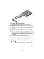
3. Fasten the inner members from Step 2 to the UPS on both sides (see
below) with eight screws provided in the accessories box of the UPS.
4. Attach the two mounting brackets to the rack’s mounting rails. The
brackets allow adjustment of up to eight inches of the slide assembly
mounting position, front-to-back, on the rack mounting rails. Deter-
mine which adjustment holes to use on the bracket, and attach it to
the slide assembly on the stationary outer member using the bar nuts
and #10-32 binding head screws provided in the slide assembly kit.
Insert two screws from the inside of each slide assembly.
5. Install the slide assemblies, with brackets attached in Step 4 into the
the rack enclosure. The return flanges on the mounting brackets and
outer members fit to the inside of the rack mounting rails.
6. Insert the eight screws loosely (finger-tight). Make sure the slide
assemblies are in the same alignment position on all four rack mount-
ing rails. After checking alignment, TIGHTEN ALL SCREWS.
NOTE
Bar nuts may not be required on all installations, depending
on the type of racks being used.
A
C
I
N
P
U
T
B
A
T
T
E
R
Y
U
P
S
ON
B
Y
P
A
S
S
Inner members
U
P
S
ta
t
io
n
G
X
T
Rack
mounting
rails
Bar nuts
Slide assemblies

11
7. Insert the UPS, with inner members attached from Step 3, into the
slide assemblies. You may need to depress the locking mechanisms
on the inner and outer members of the slide assemblies to allow the
slides to retract. The UPS should move smoothly forward and back-
ward on the slide assemblies. If not, recheck alignment.
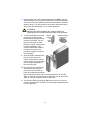
8. To orient the display for horizon-
tal viewing, remove the front
plastic bezel by pulling forward
evenly on both sides. The unit
has two front panel overlays.
Remove the outer overlay (used
for tower installation). This
reveals a horizontally oriented
front panel overlay for rack
mounting. Snap the front bezel
back into place.
9. Once the UPS is installed in the
rack, the load may be con-
nected. Ensure the load equip-
ment is turned off; plug all loads
into the output receptacles on
the rear of the UPS.
10. Plug the UPS into a dedicated
wall receptacle properly pro-
tected by a circuit breaker or
fuse in accordance with national
and local electrical codes. Use a 15 amp rated device for the 700,
1000, or 1500 VA units, 20 amp for the 2000 VA, and 30 amp for the
3000 VA. The wall receptacle must be grounded.
11. Turn ON the UPS by pressing the ON button; then turn on the con-
nected load equipment. The UPS is now providing conditioned power
to your equipment.
!
CAUTION
Reduce the risk of tipping the rack enclosure by
placing the UPS in the lowest possible rack position.
+
–
UPStation GXT
AC INPUT BATTERY UPS ON BYPASS
+
–
UPStation GXT
AC INPUT BATTERY UPS ON BYPASS
Vertical
overlay
for
tower
UPS
Horizontal overlay
for rack UPS

12
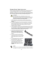
EXTERNAL BATTERY CABINET INSTALLATION
Optional Liebert external battery cabinets may be connected to the UPS
to provide additional battery run time. External battery cabinets are
designed to be placed all on one side of the UPS or stacked beneath the
UPS. There is no limit to the number of external battery cabinets that can
be used but each cabinet will increase the battery recharge time.
1. Visually inspect the external battery cabinet for freight damage.
Report damage to the carrier and your local dealer or Liebert repre-
sentative.
2. For slide rail installations, first remove the top/side fin. Top/side fin
slides forward and then lift up to remove. Optional rack-mount han-
dles are shipped with the external battery cabinet and may be
installed at this time if desired.
3. Securing hardware and slide rails are sold separately. Please contact
your local dealer or Liebert representative for these additional options
and any assistance needed. Fasten the slides into position with the
screws per the instructions included with the slide rails.
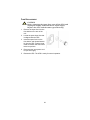
4. Use the enclosed support bases for the
tower option to prevent tip-over. One
additional set of support base exten-
sions ships with each external battery
cabinet.
5. Connect the supplied external battery
cabinet cable to the rear of the external
battery cabinet, then to the rear of the
UPS.
6. Turn the battery breaker on the rear of
the external battery cabinet “ON”.
7. The UPS is now equipped with addi-
tional backup battery runtime. For
approximate battery runtimes refer to
the Battery Run Times charts in this
manual.
!
CAUTION
The external battery cabinet(s) are heavy (see
Specifications section). External battery cabinets can
be used in rack-mount or tower configuration. Take
proper precautions when lifting them.
NOTE
You must use the included Configuration Program to program
the UPS for the number of external battery cabinets connected.

13
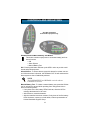
CONTROLS AND INDICATORS
ON/Alarm Silence/Manual Battery Test Button
This button controls output power to connected load(s) and has
three functions:
•ON
• Alarm Silence
• Manual Battery Test
ON - Pressing this button will start up the UPS in order to provide condi-
tioned and protected power.
Alarm Silence - To silence alarms, press this button for at least one sec-
ond. After the alarm is silenced, the UPStation GXT 2U will reactivate the
alarm system to alert of additional problems.
Manual Battery Test - To initiate a manual battery test, press the ON but-
ton for at least one second while operating from utility power with no
alarm conditions present.
• If only three of the five battery LEDs illuminate, allow the UPS to
recharge the batteries for 24 hours.
• After 24 hours, retest the batteries.
• After the batteries have been retested, if only three of the five battery
LEDs illuminate, contact your local dealer, Liebert representative or
Liebert Worldwide Support Group.
NOTE
The LOW BATTERY and BYPASS reminder alarms
CANNOT be silenced.
All LEDs illuminated
for illustrative purposes only.

14
Standby/Manual Bypass Button
This button controls output power to connected load(s) and has
dual functions: Standby and Manual Bypass.
Load/Battery Level Indicators (4 Green, 1 Amber)
The Load/Battery Level indicators have dual functions. During normal
mode operation LED indicators display the approximate electrical load
placed upon the UPS; and during battery mode operation LED indicators
display approximate battery capacity.
The UPStation GXT 2U is equipped with automatic and remote battery
test features. The automatic test occurs every 14 days (this option is user
configurable) if utility has not been interrupted. Should the battery fail this
test, the red fault indicator LED along with the A and C diagnostic LEDs
will illuminate and an alarm will sound (refer to Troubleshooting section).
The remote test feature functions with MultiLink
®
3 software and can
remotely initiate the battery test.
Fault Indicator LED (Red)
The Fault indicator LED is illuminated if the UPS has detected a problem.
Also, one or more of the load/battery level indicators may be illuminated
(refer to Troubleshooting section).
Bypass Indicator LED (Amber)
The Bypass indicator LED is illuminated when the UPS is operating from
bypass power. An alarm will sound indicating the UPS detected a prob-
lem, or the manual bypass function has been activated.
UPS ON Indicator LED (Green)
The UPS ON indicator LED is illuminated when the UPS inverter is oper-
ating and supplying power to your connected loads.
Battery Indicator LED (Amber)
The Battery indicator LED is illuminated when the UPS is operating on
battery.
AC Input Indicator LED (Green)
The AC Input indicator LED is illuminated when utility power is available
and within the input specifications.
!
CAUTION
Pressing the Standby/Manual Bypass button once will
cause the load to be transferred to bypass power.
Pressing the Standby/Manual Bypass button a second
time within 4 seconds will result in loss of power to
the output receptacles and connected loads. Perform
all necessary shutdown procedures on connected
loads before pressing this button twice.

15
Output Voltage Selection
The Output Voltage is user configurable, and is designed to allow select-
ing or changing the desired output voltage to match the utility via the
GXT2 Configuration Program provided with the UPS. The settings to
choose from are 100, 110, 115, 120, and 127 VAC output. The factory
default setting is 120 VAC.
!
CAUTION
Never change the voltage settings while the UPS is ON
and powering connected loads.
NOTE
Setting output voltage to 100 VAC will cause the UPS unit to
be derated (700/1000 VA to 90%, 1500/2000/3000 VA to
80%) of the VA and Watt ratings listed in the Specifications
section.

16
OPERATING INSTRUCTIONS
NORMAL MODE OPERATION
During normal operation, utility
power provides energy to the
UPS. The filters, power factor
correction circuit and the
inverter process this power to
provide computer grade
power to connected loads.
The UPS maintains the batter-
ies in a fully charged state.
The four green LEDs indicate an approximate level of load in 25% incre-
ments. If the UPS becomes loaded beyond full rating, the fifth (amber)
LED indicator will illuminate and sound an audible alarm. The display
template indicates the percentage of load (50% of load shown in exam-
ple) on the UPS output.
BATTERY MODE OPERATION
Battery mode occurs in event
of an extreme input voltage
condition or complete utility
failure. The battery system
supplies power through the
DC to DC converter to the
inverter to generate power
for the connected load.
During battery mode an alarm
sounds every 10 seconds.
This will change to two beeps every 5 seconds when battery runs low
(approximately 2 minutes remaining, but this is user configurable). The AC
Input LED will extinguish, and the Battery LED will illuminate to warn that a
utility problem has occurred. Each load/battery level indicator represents a
20% capacity level. As capacity decreases, fewer indicators remain illumi-
nated. Refer to Troubleshooting section.
For approximate battery run times, refer to Battery Run Times charts in
this manual. To increase this time, turn off non-essential pieces of equip-
ment (such as idle computers and monitors) or add the optional external
battery cabinet.
BATTERY RECHARGE MODE
Once utility power is restored, the UPS resumes normal operation. At this
time, the Battery Charger begins recharging the battery.
!
CAUTION
Turning off the UPS while in battery mode will result
in loss of output power.
Normal Mode Operation at 50%
AC INPUT BATTERY UPS ON BYPASS
Battery Mode Operation at 80 - 61%
AC INPUT BATTERY UPS ON BYPASS
Page is loading ...
Page is loading ...
Page is loading ...
Page is loading ...
Page is loading ...
Page is loading ...
Page is loading ...
Page is loading ...
Page is loading ...
Page is loading ...
Page is loading ...
Page is loading ...
Page is loading ...
Page is loading ...
Page is loading ...
Page is loading ...
Page is loading ...
Page is loading ...
-
 1
1
-
 2
2
-
 3
3
-
 4
4
-
 5
5
-
 6
6
-
 7
7
-
 8
8
-
 9
9
-
 10
10
-
 11
11
-
 12
12
-
 13
13
-
 14
14
-
 15
15
-
 16
16
-
 17
17
-
 18
18
-
 19
19
-
 20
20
-
 21
21
-
 22
22
-
 23
23
-
 24
24
-
 25
25
-
 26
26
-
 27
27
-
 28
28
-
 29
29
-
 30
30
-
 31
31
-
 32
32
-
 33
33
-
 34
34
-
 35
35
-
 36
36
-
 37
37
-
 38
38


Liebert Liebert UPStation GXT2U User manual
- Type
- User manual
- This manual is also suitable for
Ask a question and I''ll find the answer in the document
Finding information in a document is now easier with AI
Related papers
-
Liebert Liebert UPStation GXT2U User manual
-
-
-
-
Avocent GXT2-6000RT208 User manual
-
Liebert UPStation GXT2000RT-230 User manual
-
-
-
-
Other documents
-
Emerson Liebert MicroPOD Maintenance Bypass and Output Distribution Accessory User guide
-
SolaHD MultiLINK Owner's manual
-
-
-
-
-
 PowerWalker DC SecureAdapter 12V Owner's manual
-
 Leonics Ultimate-X 3000VA User manual
-
-
Epcom EPU500L User manual

