
• To prevent electrical fire or shock hazard, do not expose this device to rain or
moisture. Do not use near a bath, washbowl, kitchen sink, laundry or any
area where the SLxRF modulator could come into contact with moisture or
water.
• To avoid electrical shock, do not open this device. There are no user
serviceable parts inside. Opening the device will invalidate the warranty.
Refer to qualified repair personnel only.
• The SLxRF modulator is for use with a UK 230VAC 50Hz mains power supply
only.
• Always be aware of electrical safety: never overload a mains socket or
extension with too many devices drawing excessive current. Doing so
increases the risk of fire and electrical shocks.
The Philex
SLxRF modulator allows you to:
• Watch 'Free-to-Air' digital satellite TV on a TV that does not have a spare
Scart/Phono connection, using the existing coaxial input
• Watch digital satellite receivers, DVDs or any AV device without an internal
modulator on a TV that does not have a spare Scart/Phono connection, using
the existing coaxial input
• Distribute the signal from any audio-visual device (digital satellite TV, DVD etc.)
to all TVs in your home
OWNER
’
S MANUAL
PLEASE READ BEFORE USE
Changes or modifications made to the devic
e
invalidate the product warranty & approval
s
!
A. Introducing the SLxRF modulator
Important safety precautions
1

The SLxRF modulator works by using an unused UHF channel on your TV to show
the signal from your AV equipment. On your TV, each terrestrial TV channel
occupies a UHF frequency. In the UK, a typical example of the fequencies used for
each channel are:
On the rear of the SLxRF modulator is a 8-way DIP switch (just below 'CHANNEL
SETTING'. By selecting the OFF (up) or ON (down) position of each of the 8
switches, you can choose any UHF channel between 21 and 69 (471.25 to
855.25MHz) for the the SLxRF modulator to display the desired AV signal.
To avoid inteference between channels, there must be a 3-channel UHF spacing
between each channel. E.g. do not set up your DVD player on channel 40 and your
satellite on channel 41. The following settings are suggested as a guide :
UHF
channel
UHF frequency
(MHz)
Switch
1
Switch
2
Switch
3
Switch
4
Switch
5
Switch
6
Switch
7
Switch
8
21 471.25 0 0 0 0 0 0 TEST
22 479.25 0 0 0 0 0 1 TEST
23 487.25 0 0 0 0 1 0 TEST
24 495.25 0 0 0 0 1 1 TEST
25 503.25 0 0 0 1 0 0 TEST
26 511.25 0 0 0 1 0 1 TEST
27 519.25 0 0 0 1 1 0 TEST
28 527.25 0 0 0 1 1 1 TEST
29 535.25 0 0 1 0 0 0 TEST
30 543.25 0 0 1 0 0 1 TEST
31 551.25 0 0 1 0 1 0 TEST
32 559.25 0 0 1 0 1 1 TEST
33 567.25 0 0 1 1 0 0 TEST
34 575.25 0 0 1 1 0 1 TEST
35 583.25 0 0 1 1 1 0 TEST
36 591.25 0 0 1 1 1 1 TEST
37 599.25 0 1 0 0 0 0 TEST
38 607.25 0 1 0 0 0 1 TEST
39 615.25 0 1 0 0 1 0 TEST
40 623.25 0 1 0 0 1 1 TEST
2
B. Setting the output frequency
TV channel UHF channel UHF frequency (MHz)
ITV1 23 487.25
BBC1 26 511.25
Channel 4 30 543.25
BBC2 33 567.25
Channel 5 36 591.25
B. Setting the output frequency (continued)
For the SLxRF modulator to
work, it must be set to use a
UHF channel that is not alread
y
used by a TV channel, or the
VCR if it is connected to your T
V
by a RF flylead (the coaxial
input).
AV equipment UHF channel UHF frequency (MHz)
VCR player 39 615.25
Satellite box 42 639.25
DVD player 45 663.25
Contact your local TV station
to check what UHF channels are
used in your area.
OFF
=
'0' position
ON
=
'1' position
2 3

UHF
channel
UHF frequency
(MHz)
Switch
1
Switch
2
Switch
3
Switch
4
Switch
5
Switch
6
Switch
7
Switch
8
41 631.25 0 1 0 1 0 0 TEST
42 639.25 0 1 0 1 0 1 TEST
43 647.25 0 1 0 1 1 0 TEST
44 655.25 0 1 0 1 1 1 TEST
45 663.25 0 1 1 0 0 0 TEST
46 671.25 0 1 1 0 0 1 TEST
47 679.25 0 1 1 0 1 0 TEST
48 687.25 0 1 1 0 1 1 TEST
49 695.25 0 1 1 1 0 0 TEST
50 703.25 0 1 1 1 0 1 TEST
51 711.25 0 1 1 1 1 0 TEST
52 719.25 0 1 1 1 1 1 TEST
53 727.25 1 0 0 0 0 0 TEST
54 735.25 1 0 0 0 0 1 TEST
55 743.25 1 0 0 0 1 0 TEST
56 751.25 1 0 0 0 1 1 TEST
57 759.25 1 0 0 1 0 0 TEST
58 767.25 1 0 0 1 0 1 TEST
59 775.25 1 0 0 1 1 0 TEST
60 783.25 1 0 0 1 1 1 TEST
61 791.25 1 0 1 0 0 0 TEST
62 799.25 1 0 1 0 0 1 TEST
63 807.25 1 0 1 0 1 0 TEST
64 815.25 1 0 1 0 1 1 TEST
65 823.25 1 0 1 1 0 0 TEST
66 831.25 1 0 1 1 0 1 TEST
67 839.25 1 0 1 1 1 0 TEST
68 847.25 1 0 1 1 1 1
TEST
69
855.25 1 1 0 0 0 0
TEST
Please note: when selecting the UHF output frequency, notice that Switch 7 is not
used. Switch 8 is used to turn the SLxRF modulator's test signal on and off.
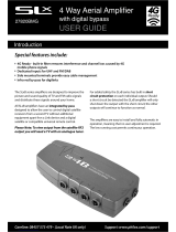
When tuning and programming the SLxRF modulator's channel into your TV, the
test signal will show if your TV is correctly tuned in. If it is correctly tuned in, a
black screen with two white stripes will show on your TV:
Depending on what AV equipment you have and how you wish to view it, there are
many different ways of connecting your equipment to the SLxRF modulator and the
modulator to your TV. The most typical examples are shown here.
You are not limited to using a single SLxRF modulator - modulators can be
connected in series so you can connect multiple pieces of equipment to your TV.
If you are in any doubt, contact our Customer CareLine (08457 573 479) or e-mail
.
C. Setting the output frequency (continued)
D. Connecting your SLxRF modulator
5
4 5

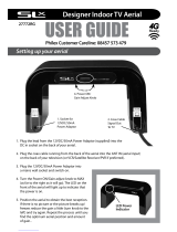
4. Alternatively, you can distribute the 'Free-to-Air' transmission to other TVs in your home by plugging
the RF flylead into an aerial amplifier (such as Philex's SLx/SLxB range).
C1. Connecting 'Free-to-Air' Digital Satellite
1. Plug the aerial into the
coaxial socket of you
r
Free-to-Air Adaptor's
(DTVA) Scart connector.
2. Plug the DTVA's Scart
adaptor into the Scart AV
input on the front of the
SLxRF modulator.
3. Using a RF (coaxial)
flylead, connect the 'TO
TV' socket on the back o
f
the SLxRF modulator to
your TV's coaxial input
C2. Connecting Satellite, Video or DVD
6
1. Plug your aerial into the
ANT IN socket at the back
of the SLxRF modulator.
2. Using a Scart to Scart
lead, connect the AV
OUTPUT socket of you
r
Satellite/VCR/DVD playe
r
to the AV INPUT at the
front of the SLx RF
modulator.
'Free-to-Air' Adaptor =
Digital TV Adaptor
(DTVA)
3. Using a RF (coaxial) flylead, connect the 'TO TV' socket on the
back of the SLxRF modulator to your TV's coaxial input.
C3. Connecting multiple SLxRF modulators
1. Ensure that each SLxRF modulator is se
t
to a different UHF channel.
2. Shown is how to connect a Satellite,
VCR and DVD player.
3. Plug your aerial into the ANT IN socket at
the back of the first SLxRF modulator.
4. Using a Scart to Scart lead, connect the
AV OUTPUT socket of you
r
Satellite/VCR player to the AV INPUT at
the front of the first SLx RF modulato
r
5. Using a RF (coaxial) flylead, connect the
'TO TV' socket on the back of the fisrt
SLxRF modulator to your ANT IN socket
of the second SLxRF modulator.
6. Using a Scart to Scart lead, connect you
r
DVD's AV output to the AV INPUT socket
at the front of the second SLxRF
modulator.
4. Alternatively, you can distribute the Satellite/VCR/DVD transmission to other TVs in your home b
y
plugging the RF flylead into an aerial amplifier (such as Philex's SLx/SLxB range).
7. Using a RF (coaxial) flylead, connect the 'TO TV' socket on the back of the second SLxRF modulato
r
to your TV's coaxial input.
8. Alternatively, you can distribute the Satellite/VCR/DVD transmission to other TVs in your home by
plugging the RF flylead into an aerial amplifier (such as Philex's SLx/SLxB range).
Connection tips
The SLxRF modulator is not limited to using Scart connections. Video and stereo audio signals can
be connected to it using the 3 Phono (or RCA) sockets at the front of the modulator. Each is colour
coded for the correct signal:
YELLOW - VIDEO INPUT RED - RIGHT AUDIO INPUT WHITE - LEFT AUDIO INPUT
Scart and Phono connections cannot be used at the same time.
6 7

Problem
Possible cause and action
No picture
• No power - check mains in on and Power indicator on
front of modulator is illuminated.
• Tuned to wrong UHF channel - check 8-way DIP
switch is set correctly
• No video input - check connections between
modulator and AV source
Poor picture
contrast
• Incorrect video level - adjust the level by turning the
VIDEO +/- control at the front of the modulator with a
small screwdriver
Blurred
picture
• Interference from TV station - adjust the 8-way DIP
switch so that there is a greater gap between UHF
channel output of the modulator and the TV station.
No sound or
poor quality
sound
• Poor audio connection - check connections between
modulator and AV source
If you are still experiencing problems, please contact our Customer CareLine on
08457 573 479 Monday to Friday, 8am to 6pm. Alternatively, e-mail
or visit http://technical.philex.com
.
PHILEX ELECTRONIC LIMITED
UNIT 1 KINGFISHER WHARF, LONDON ROAD
BEDFORD MK42 0PA
www.philex.com
I LAP metsyS
Bd4+~2-:zHM0001~04 VT OT TNA
)m(2-961CEI/)f(2-961CEI troP VT/TNA
RF Output 470~860MHz Adj. (CH 21-69 Adj.)
RF Output Level
70dBµV (Picture Carrier)
zHM0.6 reirrac-buS oiduA
Audio Carrier O/P
Level
Compare to Video
Carrier
-15dB
Audio/Video Input
Port
Phono jack or Scart
Video Input Level Adjustable,Recommend 1Vpp
Video Input
Impedance
75Ω
ppV1 dnemmoceR leveL tupnI oiduA
Audio Input
Impedance
13KΩ
Power Supply 240VAC or 230VAC or 220VAC, 50Hz
D. Troubleshooting
E. Technical Specifications
Part of the range of Philex SLx Aerial Accessories
9
8
-
 1
1
-
 2
2
-
 3
3
-
 4
4
-
 5
5


Ask a question and I''ll find the answer in the document
Finding information in a document is now easier with AI
Related papers
Other documents
-
 ANTIhum.com CCT818 Operating instructions
-
König SAT-MOD4 Datasheet
-
 SLX 27820BMG User manual
-
 SLX Designer Indoor TV Aerial User manual
-
Teleco Falcon 12 DTVA User manual
-
Maximum MT57 Installation guide
-
Marmitek MegaView 70 User manual
-
DRAKE VMM806AG User manual
-
GSS HRC 312 AV S Assembly Instructions Manual
-


