GE JVX3240DJWW Owner's manual

Category
Cooker hoods
Type
Owner's manual
Write the model and serial
numbers here:
Model # _________________
Serial # _________________
You can find them on a label
on the inside of the hood.
ESPAÑOL
Para consultar una version en
español de este manual de
instrucciones, visite nuestro sitio de
internet GEAppliances.com.
RANGE HOODS
49-80783-3 08-16 GEA
SAFETY INFORMATION ...........3
USING THE HOOD
Controls ................................5
Chef Connect ...........................6
CARE AND CLEANING
Filters ..................................7
Surfaces ................................8
Lights ..................................8
INSTALLATION INSTRUCTIONS ..9
TROUBLESHOOTING TIPS ........20
WARRANTY ........................ 21
ACCESSORIES .....................22
CONSUMER SUPPORT ............24
JVX3240
JVX3300
JVX5300
JVX5360
JVX5305
JVX5365
PVX7300
PVX7360
OWNER’S MANUAL &
INSTALLATION
INSTRUCTIONS
GE is a trademark of the General Electric Company. Manufactured under trademark license.
991.0480.237
2 49-80783-3
THANK YOU FOR MAKING GE APPLIANCES A PART OF YOUR HOME.
Whether you grew up with GE Appliances, or this is your first, we’re happy to have you in the family.
We take pride in the craftsmanship, innovation and design that goes into every GE Appliances
product, and we think you will too. Among other things, registration of your appliance ensures that we
can deliver important product information and warranty details when you need them.
Register your GE appliance now online. Helpful websites and phone numbers are available in the
Consumer Support section of this Owner’s Manual. You may also mail in the pre-printed registration
card included in the packing material.
49-80783-3 3
SAFETY INFORMATION
IMPORTANT SAFETY INFORMATION
READ ALL INSTRUCTIONS BEFORE USING
READ AND SAVE THESE INSTRUCTIONS
WARNING
TO REDUCE THE RISK OF FIRE,
ELECTRIC SHOCK OR INJURY TO PERSONS,
OBSERVE THE FOLLOWING:
A. Use this unit only in the manner intended by the
manufacturer. If you have questions, contact the
manufacturer.
B. Before servicing or cleaning unit, switch power off
at service panel and lock the service disconnecting
means to prevent power from being switched
on accidentally. When the service disconnecting
means cannot be locked, securely fasten a
prominent warning device, such as a tag, to the
service panel.
C. Do not use this unit with any solid-state speed
control device.
D. This unit must be grounded.
WARNING
TO REDUCE THE RISK OF A
RANGE TOP GREASE FIRE:
A. Never leave surface units unattended at high
settings. Boilovers cause smoking and greasy
spillovers that may ignite. Heat oils slowly on
medium settings.
B. Always turn hood ON when cooking at high heat or
when flambéing food (i.e. Crepes Suzette, Cherries
Jubilee, Peppercorn Beef Flanbé).
C. Clean ventilating fans frequently. Grease should not
be allowed to accumulate on fan or filter.
D. Use proper pan size. Always use cookware
appropriate for the size of the surface element.
WARNING
TO REDUCE THE RISK OF INJURY
TO PERSONS IN THE EVENT OF A RANGE TOP
GREASE FIRE, OBSERVE THE FOLLOWING*:
A. SMOTHER FLAMES with a close-fitting lid, cookie
sheet or metal tray, then turn off the burner. BE
CAREFUL TO PREVENT BURNS. If the flames do
not go out immediately, EVACUATE AND CALL
THE FIRE DEPARTMENT.
B. NEVER PICK UP A FLAMING PAN—You may be
burned.
C. DO NOT USE WATER, including wet dishcloths or
towels—a violent steam explosion will result.
D. Use an extinguisher ONLY if:
1. You know you have a Class ABC extinguisher,
and you already know how to operate it.
2. The fire is small and contained in the area where
it started.
3. The fire department is being called.
4. You can fight the fire with your back to an exit.
* Based on “Kitchen Fire Safety” published by NFPA.
CAUTION
FOR GENERAL VENTILATING USE
ONLY. DO NOT USE TO EXHAUST HAZARDOUS
OR EXPLOSIVE MATERIALS AND VAPORS.
4 49-80783-3
SAFETY INFORMATION
IMPORTANT SAFETY INFORMATION
READ ALL INSTRUCTIONS BEFORE USING
How to Remove Protective Shipping Film and Packaging Tape
Carefully grasp a corner of the protective shipping film
with your fingers and slowly peel it from the appliance
surface. Do not use any sharp items to remove the film.
Remove all of the film before using the appliance for the
first time.
To assure no damage is done to the finish of the
product, the safest way to remove the adhesive from
packaging tape on new appliances is an application of
a household liquid dishwashing detergent. Apply with a
soft cloth and allow to soak.
NOTE: The adhesive must be removed from all parts.
READ AND SAVE THESE INSTRUCTIONS
REMOTE ENABLE EQUIPMENT (on some models)
This device complies with part 15 of the FCC Rules.
Operation is subject to the following two conditions: (1)
This device may not cause harmful interference, and
(2) this device must accept any interference received,
including interference that may cause undesired
operation.
The wireless communication equipment installed on
this hood has been tested and found to comply with
the limits for a Class B digital device, pursuant to part
15 of the FCC Rules. These limits are designed to:
(a) provide reasonable protection against harmful
interference in a residential installation. This
equipment generates, uses, and can radiate radio
frequency energy and, if not installed and used in
accordance with the instructions, may cause harmful
interference to radio communications. However, there
is no guarantee that interference will not occur in a
particular installation. If this equipment does cause
harmful interference to radio or television reception,
which can be determined by turning the equipment off
and on, the user is encouraged to try to correct the
interference by one or more of the following measures:
Ŷ5HRULHQWRUUHORFDWHWKHUHFHLYLQJDQWHQQD
Ŷ,QFUHDVHWKHVHSDUDWLRQEHWZHHQWKHHTXLSPHQWDQG
receiver.
Ŷ&RQQHFWWKHHTXLSPHQWLQWRDQRXWOHWRQDFLUFXLW
different from that to which the receiver is
connected.
Ŷ&RQVXOWWKHGHDOHURUDQH[SHULHQFHGUDGLR79
technician for help.
(b) accept any interference received, including
interference that may cause undesired operation of the
device.
Note that any changes or modifications to the wireless
communication device installed on this oven that are
not expressly approved by the manufacturer could void
the user’s authority to operate the equipment.
49-80783-3 5
1. Rangehood Control Panel: The control panel
is located on the front of the canopy.
2. Light Button: 2Q1LJKW2IIVZLWFKIRUWKHOLJKWV
Press the LIGHT button to turn the lights on, again
to set the lights to night setting, and again to turn off.
3. Fan Off Button: Off switch for the fan. The fan
can be operated by pressing any of the fan setting
buttons. Hold for 3 seconds to activate auto off after
15 minutes.
4. Fan Settings Buttons: Speed control for
fan. Press the button Lo for LOW speed, Med for
MEDIUM speed and Hi for HIGH speed. Hold down
the Hi button for 3 seconds to activate the BOOST
SPEED that will run for 10 minutes.
4
1
23
On Some Models
On Some Models
1. Rangehood Control Panel: The control panel
is located on the front of the canopy.
2. Light Switch: Light switch toggles between
On and Off.
3. Fan Power Switch: The power switch toggles
between fan settings Hi, Lo, and Off.
Controls
USING THE HOOD: Controls
Light Fan
On
Off
Hi
Lo
Off
1
23
6 49-80783-3
1. Rangehood Control Panel: The glass touch
control panel is located on the front of the canopy.
2. Light Pad: 2Q1LJKW2IIVZLWFKIRUWKHOLJKWV
Press the LIGHT pad to turn the lights on, again to
set the lights to night setting, and again to turn off.
3. Auto Off Pad: Off switch for the fan. The fan
can be operated by pressing any of the fan setting
pads. Hold for 3 seconds to activate auto off after
15 minutes.
4. Fan Settings Pads: Speed control for fan.
Press the pad Lo for LOW speed, Med for MEDIUM
speed and Hi for HIGH speed. Hold down the Hi
button for 3 seconds to activate the BOOST SPEED
that will run for 10 minutes.
5. Chef Connect: This is a Bluetooth
®
pairing
feature for use with other compatible Chef Connect
enabled products on a cooktop or a range. When
the device is paired, the light and fan will turn
ON at the Default Sync Settings upon receiving a
command from the range or cooktop. It will remain
ON at that setting until the user changes it.
On Some Models
4
1
32
Controls
Chef Connect
USING THE HOOD: &RQWUROV&KHI&RQQHFW
5
Chef Connect Operation Bluetooth
®
Connection
To pair with another device:
To start the pairing process on the hood, press and hold
the Light pad for 3 seconds. The backlight for the Lo –
Med – Hi – Light will flash in that sequence until the hood
is paired with the range or other device. If the pairing is
successful, all 4 lights (Lo, Med, Hi, and Light) will flash
three times simultaneously and then turn off.
It will time out after 2 minutes if pairing is not completed.
After which the pairing sequence will need to be restarted.
To cancel pairing:
To cancel the pairing hold the Light pad for 3 seconds
and then turn off the hood.
Default Sync Settings:
The factory default setting for the light will be the
brightest.
The factory default setting for the fan sync will be OFF.
The user can change the Default Sync Settings by
pressing and holding the Lo pad for 3 seconds. This will
enter the Default Settings Mode. Once in this mode, the
backlights for all buttons (Lo, Med, Hi, and Light) will
EOLQN2Q2IILQGHILQLWHO\DQGWKHIDQDQGOLJKWZLOOVZLWFK
to the current Default Sync Setting, so the user knows
what the current default value is. At this time, set the light
and fan to the desired default levels. Once the user is
satisfied with the selection, press and hold the Off pad
for 3 seconds. This will exit this mode. At that time the
backlights will stop blinking and the state of the fan and
light will change back to their prior state before entering
the Default Settings Mode.
49-80783-3 7
Be sure the circuit breaker is off and all surfaces are cool before cleaning or servicing any part of the vent hood.
Metal Grease Filter
The metal filters trap grease during cooking.
The filter must ALWAYS be in place when the hood is in
use. The grease filter is dishwasher-safe and should be
cleaned every 6 months, or as needed.
To remove:
Pull downward on the filter lock to release the filter.
To replace:
Fit the tabs at the bottom of the filter into the slots in the
back of the filter opening. Lift up the front side of the filter
and push gently until the filter locks into place. Make sure
the filter lock is in the closed position to secure the filter.
To clean, swish the filter in hot soapy water and rinse
in clean water or wash it in the dishwasher. Do not use
abrasive cleansers.
NOTE: Some discoloration may occur in the dishwasher.
Charcoal Filter (for recirculation installation only)
If the model is not vented to the outside, the air needs to
be recirculated through a disposable charcoal filter that
helps remove smoke and odors.
NOTE: DO NOT rinse, or put charcoal filter in an
automatic dishwasher.
The charcoal filter cannot be cleaned. It must be
replaced. It is recommended that the charcoal filter
be replaced every 6-12 months or if it is noticeably
dirty or discolored.
To inquire about purchasing replacement charcoal filters
or to find the location of a dealer nearest you, please call
our toll-free number:
National Parts Center 800.626.2002
To install (on some models):
1. Remove the metal filters—see Metal Grease Filter
section.
2. Place the side of the charcoal filter with the tabs
against the bottom of the blower.
3. Drive screws in the 2 locations shown in the picture.
4. Replace the metal filters—see Metal Grease Filter
section.
To remove:
1. Remove the metal filters—see Metal Grease Filter
section.
2. Remove the 2 screws holding the charcoal filter in
place to remove.
Filters
CARE AND CLEANING: Filters
NOTE: For this
configuration one grease
filter is only used in the
vented mode.
Charcoal filter included on this model.
Charcoal filter not included on this model.
Call National Parts Center 800.626.2002 to order.
NOTE: For this
configuration charcoal
filter is installed in
place of grease filter.
8 49-80783-3
Lights
Stainless Steel Surfaces (on some models)
Do not use a steel wool pad; it will scratch the
surface.
To clean the stainless steel surface, use warm sudsy
water or a stainless steel cleaner or polish. Always wipe
the surface in the direction of the brush line. Follow
the cleaner instructions for cleaning the stainless steel
surface. Cleaners with oxalic acid such as Bar Keepers
Friend Soft Cleanser™ will
remove surface rust, tarnish, and
small blemishes. To receive a
$2.00 coupon for a trial sample
of Bar Keepers Friend Soft
Cleanser™ follow the link below
or scan the QR Code.
www.barkeepersfriend.com/ge
Use only a liquid cleanser free of grit and rub in the
direction of the brush lines with a damp soft sponge.
To inquire about purchasing stainless steel appliance
cleaner or polish, or to find the location of a dealer
nearest you, please call our toll-free number:
National Parts Center
800.626.2002
GEApplianceParts.com
Painted Surfaces (on some models)
Do not use a steel wool pads or other abrasive
cleaners; they will scratch the surface.
Clean grease-laden surfaces of the hood frequently. To
clean the hood surface, use a hot, damp cloth with a
mild detergent suitable for painted surfaces. About one
tablespoon of ammonia may be added to the water. Use
a clean, hot, damp cloth to remove soap. Dry with a dry,
clean cloth.
NOTE: When cleaning, take care not to come in contact
with filters and other surfaces.
CAUTION
When cleaning the hood surfaces,
be certain that you do not touch the light with moist
hands or cloth. A warm or hot light may break if
touched with a moist surface. Always let the light
cool completely before cleaning around it.
CAUTION
Allow lights to cool before touching.
On Some Models
1. Before attempting to replace the lights, make sure that
the light switch is turned off.
2. Remove light cover.
3. Unscrew light counterclockwise to unlock light and
pull out.
4. Replace with new light of same type (standard
incandescent), making sure socket is properly inserted
into the housing of the lamp holder.
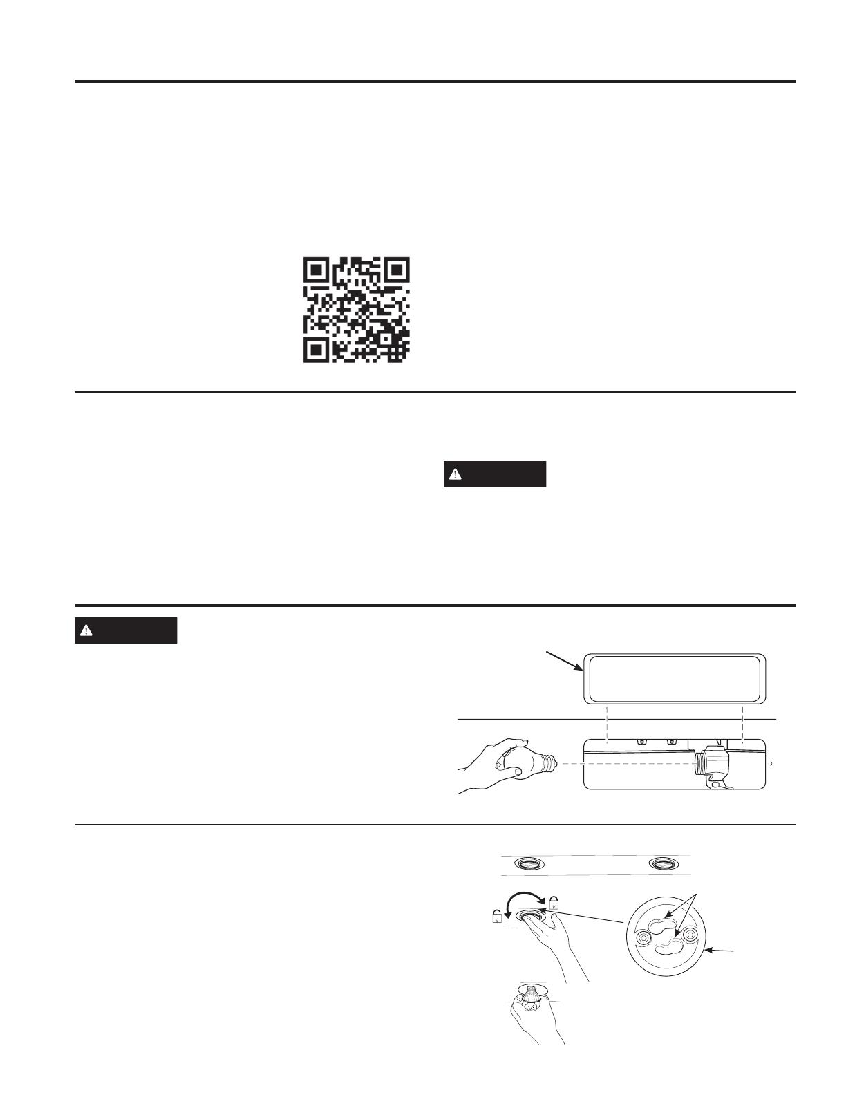
On Some Models
1. Before attempting to replace the lights, make sure that
the light switch is turned off.
2. Rotate light counterclockwise to unlock and pull out.
Wearing latex gloves may offer a better grip.
3. Replace with new light of same type, making sure
pins are inserted properly into the sockets of the lamp
holder and turn clockwise to lock.
All lamps need to be GU10 compatible.
Surfaces
CARE AND CLEANING:6XUIDFHV/LJKWV
Light Cover
Rotate the lamp until the
pins are located in narrow
neck of the socket.
Lamp
Holder
Sockets
49-80783-3 9
Installation
Instructions
INSTALLATION INSTRUCTIONS
BEFORE YOU BEGIN
Read these instructions completely and
carefully.
IMPORTANTSave these
instructions for local inspector’s use.
IMPORTANT Observe all governing
codes and ordinances.
Note to Installer – Be sure to leave these
instructions with the Consumer.
Note to Consumer – Keep these instructions for
future reference.
Skill level – Installation of this vent hood requires
basic mechanical and electrical skills.
Proper installation is the responsibility of the
installer.
Product failure due to improper installation is not
covered under the Warranty.
FOR YOUR SAFETY
WARNING
Before beginning the installation,
switch power off at service panel and lock the
service disconnecting means to prevent power from
being switched on accidentally. When the service
disconnecting means cannot be locked, securely
fasten a prominent warning device, such as a tag,
to the service panel.
CAUTION
To reduce risk of fire and to
properly exhaust air, be sure to duct air outside.
Do not vent exhaust air into spaces within walls or
ceilings or into attics, crawl spaces or garages.
WARNING
Disconnect all electrical power
at the main circuit breaker or fuse box before
installing.
Under the Cabinet (UTC) Hoods
JVX3240, JVX3300, JVX5300, JVX5360, JVX5305,
JVX5365, PVX7300, PVX7360
WARNING
TO REDUCE THE RISK OF FIRE,
ELECTRIC SHOCK OR INJURY TO PERSONS,
OBSERVE THE FOLLOWING:
A. Installation work and electrical wiring must be
done by qualified person(s) in accordance with
all applicable codes and standards, including
fire-rated construction.
B. Sufficient air is needed for proper combustion
and exhausting of gases through the flue
(chimney) of fuel burning equipment to prevent
back drafting. Follow the heating equipment
manufacturer’s guidelines and safety standards
such as those published by the National Fire
Protection Association (NFPA), the American
Society for Heating, Refrigeration and Air
Conditioning Engineers (ASHRAE) and the local
code authorities.
C. When cutting or drilling into wall or ceiling, do
not damage electrical wiring and other hidden
utilities.
D. Ducted fans must always be vented to the
outdoors.
WARNING
TO REDUCE THE RISK OF FIRE,
USE ONLY METAL DUCT WORK.
“If you have questions, call GE Appliances at 800.GE.CARES (800.432.2737)
or visit our website at: GEAppliances.com”
10 49-80783-3
DUCTWORK REQUIREMENTS
WARNING
TO REDUCE THE RISK OF FIRE, USE ONLY METAL DUCTWORK.
NOTE: Read the ductwork sections only if you do not have existing ductwork. If you have existing ductwork, skip
to the “Damage” section and proceed.
The venting system must exhaust to the outside.
This hood can be vented vertically through upper cabinets or horizontally through an outside wall. Ductwork is
not included.
Exhaust connection
This hood is designed to be vented vertically using a 7" round duct or a 3
1
»4” x 10” rectangular duct or
horizontally using a 3
1
»4” x 10” rectangular duct. Do not use less than a 7” diameter duct.
Duct length
The ducting from this fan to the outside of the building has a strong effect on the air flow, noise and energy use
of the fan. Use the shortest, straightest duct routing possible for best performance, and avoid installing the fan
with smaller ducts than recommended. Insulation around the ducts can reduce energy loss and inhibit mold
growth. Fans installed with existing ducts may not achieve their rated air flow.
NOTE: For an ENERGY STAR
®
model, unit must be vented mode to be considered ENERGY STAR
®
certified.
INSTALLATION PREPARATION
Installation Preparation
INSULATION AND/OR CAULK AROUND THE DUCTS
Cabinet
Hood
Add Insulation
DQGRU&DXON
Add tape to joint
Add Insulation
DQGRU&DXON
Roof Cap
Round or Rectangular Duct
Wall Cap
49-80783-3 11
Installation Preparation
MOUNTING SPACE
PRODUCT DIMENSIONS
NOTES:
Hood width may be greater than the width of the
range or cooktop, but it may not be smaller.
Installation height should be measured from the
cooking surface to the lowest part of the hood.
This hood must be installed onto a cabinet. It can
be vented to the outdoors, or it can be installed for
recirculating operation.
Bottom edge
of cabinet
needs to
be 30” or
more from
the cooking
surface
24" Min required
30" Max recommended
to the bottom of
the hood
34"-36"
Typical
ƎƎRUƎ to
match cooktop width
INSTALLATION PREPARATION
*Controls may vary
Top View
Back View
X20”
5”7
1
»2
ø 7”
4”
3
1
»4
1
»2
3
»4
5
1
»2
12”
Size X
24” 23
15
»16
30” 29
15
»16
36” 35
15
»16
5”7
1
»2
3
1
»4
3
»4
3
»4
12 49-80783-3
INSTALLATION PREPARATION
REMOVE THE PACKAGING
CAUTION
Wear gloves to protect against
sharp edges.
Remove the hardware bag, literature package and
other boxed parts.
Remove and properly discard the protective plastic
wrapping and other packaging materials.
TOOLS AND MATERIALS
REQUIRED
(NOT SUPPLIED)
:LUHFXWWHUVWULSSHU
Spirit level
Aluminized
Duct tape
Torx 10, 15, 20
driver
Charcoal Filter (required
for some models in
recirculation mode)
Safety glasses
Strain relief for
junction box
Electric drill, #2 Phillips,
flat head, and
9
»32" drill bit
UL listed wire nuts
Pencil and tape measure
PLAN THE INSTALLATION
CAUTION
To reduce risk of fire and to
properly exhaust air, be sure to duct the air outside
– Do not vent exhaust air into spaces within walls or
ceilings or into attics, crawl spaces, or garages.
PARTS SUPPLIED FOR
INSTALLATION
1 Hardware Package
• 1 Literature Package
• 1 Vented Mode Deflector Part
PARTS NEEDED FOR INSTALLATION
1 Strain Relief
• Power Supply Cable
• 1 Wall or Roof Cap (for external venting only)
• All Metal Ductwork (for external venting only)
NOTE: This range hood can be installed as either
ducted or recirculation. In a ducted application,
this range hood can be vented through the wall or
ceiling. When installed for recirculation, the range
hood vents out the front of the hood.
NOTE: Before making any cuts or holes for
installation, determine which venting method will be
used and carefully calculate all measurements.
Installation Preparation
49-80783-3 13
INSTALLATION PREPARATION
Installation Preparation
INSTALLATION DIMENSIONS
RANGE HOOD COMPONENTS
A. Hood Body
B. 'DPSHU'XFW&RQQHFWRU
C. Mounting Bracket
D. Screws (4)
E. Screws (4)
F. Screws (6)
HARDWARE COMPONENTS
DE F
C
C
B
A
D
D
E
F
E
12"
X
X = Distance from hood to cooktop
(varies depending on installation)
Required Min. = 24"
Recommended Max. = 30"
34"-36"
Typical
F
For vented
mode only
14 49-80783-3
INSTALLATION PREPARATION
Installation Preparation
POWER SUPPLY
IMPORTANT – (Please read carefully)
WARNING
FOR PERSONAL SAFETY, THIS APPLIANCE
MUST BE PROPERLY GROUNDED.
Remove house fuse or open circuit breaker before
beginning installation.
Do not use an extension cord or adapter plug with
this appliance. Follow National Electrical Codes or
prevailing local codes and ordinances.
Electrical supply
These vent hoods must be supplied with 120V,
60Hz, and connected to an individual, properly
grounded branch circuit, and protected by a 15 or
20 amp circuit breaker or time delay fuse.
• Wiring must be 2 wire with ground.
If the electrical supply does not meet the above
requirements, call a licensed electrician before
proceeding.
Route house wiring as close to the installation
location as possible in the ceiling or wall.
Connect the wiring to the house wiring in
accordance with local codes.
Grounding instructions
The grounding conductor must be connected to
a ground metal, permanent wiring system, or an
equipment-grounding terminal or lead on the hood.
WARNING
The improper connection of the
equipment-grounding conductor can result in a risk
of electric shock. Check with a qualified electrician
or service representative if you are in doubt
whether the appliance is properly grounded.
ADVANCE PLANNING
Vented Install Planning
This hood is designed to be vented vertically using
a 7" round duct or a 3
1
»4" x 10" rectangular duct or
horizontally using a 3
1
»4" x 10" rectangular duct.
• Use metal ductwork only.
• Determine the exact location of the vent hood.
Plan the route for venting exhaust to the outdoors.
To maximize the ventilation performance of the
vent system:
1. Minimize the duct run length and number of
transitions and elbows.
2. Maintain a constant duct size.
3. Seal all joints with duct tape to prevent any
leaks.
4. Do not use any type of flexible ducting.
Install a wall cap or roof cap at the exterior
opening. Purchase the wall or roof cap and any
transition and length of duct needed in advance.
When applicable, install any makeup (replacement)
air system in accordance with local building
code requirements. Visit GEAppliances.com for
available makeup air solutions.
Recirculation Install Planning
This hood may be installed in recirculation mode
and is shipped in this configuration. The charcoal
filter is necessary for recirculation installation.
This part may need to be ordered separately
depending on model.
Power Supply Planning
The location of the power supply connection is
called out in the Prepare for Electrical and Venting
section on page 15.
49-80783-3 15
1
SELECT VENT OPTION THAT
YOUR INSTALLATION WILL
REQUIRE (A-D)
A
Outside top exhaust
(Vertical duct—3
1
»4” x 10” Rectangular)
B
Outside top exhaust
(Vertical duct—7” Round)
C
Outside rear exhaust
(Horizontal duct—3
1
»4” x 10”
Rectangular)
D
Recirculating
(Unit is configured from factory in
this mode)
2
PREPARING MOUNTING
For cabinets with dimensions below, the
mounting bracket may be used for any model.
Otherwise, the hood must mount directly
to bottom of cabinet. Wood shims may be
needed for cabinets with a recessed bottom.
Skip to step B.
A
To install the mounting bracket
Drive (E) screws in partway into mounting
bracket. The bracket labeled "R" will be
used on the right side of the cabinet and the
bracket labeled "L" will be used on the left
side of the cabinet.
Under the cabinet that you are placing the
range hood, attach the mounting bracket as
shown below with (F) screws. Make sure
orientation is correct. Brackets should be
located against the back wall and flush with
the bottom of the cabinet.
NOTE: Repeat on left side.
INSTALLATION PREPARATION
Installation Preparation
X
3
»4" Depth
Push
against
wall
Flush
with
cabinet
Cabinet X
24” 22
1
»2
30” 28
1
»2
36” 34
1
»2
E
16 49-80783-3
2
PREPARING MOUNTING (Cont)
B
To install to the bottom of cabinet
Use the diagram or hood as a template and
mark the locations on the cabinet for the
keyholes screws.
Drive the 4 (F) screws partway into the bottom
of the cabinet (or wood shims).
INSTALLATION PREPARATION
Installation Preparation
3
PREPARE FOR ELECTRICAL
AND VENTING
Select the vent option that your installation will
require and proceed to that section:
A
Outside top exhaust
(Vertical duct–3
1
»4” x 10” Rectangular)
Use the diagram as a template and mark the
locations on the cabinet for ductwork and
electrical wiring.
B
Outside top exhaust
(Vertical duct–7” Round)
Use the diagram as a template and mark the
locations on the cabinet for ductwork and
electrical wiring.
C
Outside rear exhaust
(Horizontal duct–3
1
»4” x 10” Rectangular)
Use the diagram as a template and mark the
locations on the cabinet for ductwork and
electrical wiring.
Center line
Electrical access
hole (in cabinet
bottom)
Cabinet front
Cabinet Bottom
Vertical duct
access hole
5
1
»4 5
1
»4
7
1
»2
ø1
1
»4
4”
1
»2
3
»4
Center line
Electrical access
hole (in cabinet
bottom)
Cabinet front
Cabinet Bottom
7
1
»2
ø1
1
»4
3
»4
Access
hole for 7”
round duct
8” DIA.
HOLE
4
1
»4
Center line
Electrical access
hole (in wall)
Cabinet Front
Cabinet
Bottom
7
1
»2
ø1
1
»4
3
»4
5
1
»4 5
1
»4
3
»4
4
1
»4
Wood shims
(recessed-bottom
cabinets only)
Center
line
Cabinet Bottom
Cabinet front
2
1
»2
10
1
»4
X
Hood mounting screws (4)
Cabinet X
24” 10
3
»4
30” 13
3
»4
36” 16
3
»4
49-80783-3 17
4
REMOVE ELECTRICAL
KNOCKOUTS
Use a flat blade screwdriver, remove the
appropriate electrical knockout from the back or
the top of the hood.
5
REMOVE JUNCTION BOX
Remove junction box from inside the hood. Set
the junction box and mounting screws aside.
6
REMOVE DUCT KNOCKOUT(S)
FOR VENTED INSTALLATION
Determine which ducting option to use.
Using a flat blade screwdriver, remove the
appropriate duct knockout(s) from the top or
back of the hood.
NOTE: If the hood is to be installed in a
recirculation, non-vented ductless manner, do not
remove any venting knockouts.
NOTE: For an ENERGY STAR
®
model, unit must
be vented mode to be considered ENERGY STAR
®
certified.
7
ATTACH
DAMPER/DUCT CONNECTOR
Attach damper/duct connector over knockout
opening with two or four (D) screws. Make sure
damper pivot is nearest to top/back edge of
hood. Remove any packaging tape to allow
damper to move freely.
INSTALLATION PREPARATION
Installation Preparation
3
1
»4” x 10” Rectangular
vertical discharge. Remove top
rectangular duct knockout only.
7” Round vertical discharge.
Remove semi-circular duct
knockout and top rectangular
duct knockout.
3
1
»4” x 10” Rectangular horizontal
discharge. Remove rear rectangular
duct knockout only.
Rectangular Ducting
Round Ducting
Damper (vertical discharge
position shown)
7RSEDFN
edge
Tape
7” round
exhaust
adaptor
Junction Box
Screws
18 49-80783-3
INSTALLATION PREPARATION
Installation Instructions
8
FOR VENTED INSTALLATIONS
On Some Models:
Install with vented mode deflector part.
On Some Models:
Install vented mode deflector part.
10
MOUNT THE UTC
Place the hood onto the partially installed
screws using the keyholes and slide the hood
back into position.
9
FEED IN WIRES
Lift the hood into position and feed the house
wiring through the wiring knockout.
1
2
11
SECURE HOOD
Tighten the mounting screws. Be sure the
screw heads are in the narrow neck of the
keyhole slot.
Keyhole (4)
Mounting
screw (4)
49-80783-3 19
12
CONNECT DUCTWORK TO
HOOD
(Ducted installations only)
Connect ducting to hood. Use duct tape to
make joints secure and airtight.
INSTALLATION INSTRUCTIONS
Installation Instructions
13
ELECTRICAL CONNECTION
1. Connect the Power Supply Cable to the range
hood. Attach the white lead of the power
supply to the white lead of the range hood
(A) with a wire nut (C). Attach the black lead
of the power supply to the black lead of the
range hood (B) with a wire nut (C). Connect
the green (D) ground wire under the green
grounding screw.
2. Replace the junction box cover.
14
FINISH THE INSTALLATION
On Some Models:
1. For recirculation: Install the charcoal filter.
2. For ducted installation: Install the grease
filters.
On Some Models:
1. For recirculation: Place the charcoal filter
(not included) in place and mount using 2
screws. Replace the grease filters.
2. For vented installation: Install the grease
filters.
B
D
C
A
20 49-80783-3
Troubleshooting tips ... Before you call for service
TROUBLESHOOTING TIPS
Save time and money! Review the charts on the following pages first and you may not need to call for service.
Problem Possible Cause What To Do
Fan/Light does not operate
when either button is
pressed
A house fuse may be blown or
a circuit breaker tripped.
Replace fuse or reset circuit breaker.
Fan does not operate when
fan Lo, Med, Hi buttons are
pressed
The blower connector is loose
or not plugged into its mating
connector.
Disconnect power to the unit. Remove the filters and
look up at the blower. If the blower connector plug is
loose or you see the connector dangling, the installer
failed to plug it in securely. See the mini manual for the
plug location and how to plug in the connector.
Loud or abnormal airflow
noise
Wrong duct size used in
installation.
Using smaller duct pipe will cause reduced venting.
Minimize the duct run length and number of transitions
and elbows. GE service technicians cannot correct this
issue if installed improperly.
Fan fails to circulate
air or moves air slower
than normal and/or fan is
making loud or abnormal
airflow noise
Obstructions in duct work. Make sure nothing is blocking the vent. Make sure your
wall or roof cap has a blade or door.
Damper blade on wall or roof
cap may not be open.
Make sure damper swings freely. Damper blades may
flip over and will not fully open when this happens.
Adjust to original position.
Metal grease filter and charcoal
filter (if present) may be dirty.
Clean the metal grease filter and replace charcoal filter
(if present). See Care and Cleaning of the Vent Hood.
Insufficient makeup
(replacement) air
Sufficient makeup (replacement) air is required for
exhausting appliances to operate to rating. Check with
local building codes, which may require or strongly
advise the use of makeup air. Visit GEAppliances.com
for available makeup air solutions.
The hood controls are not
operating correctly
Control logic confused. Disconnect power to the hood by resetting the circuit
breaker. Wait 30 seconds to allow controls to reset.
Early light failure Light wattage is too high. Replace with correct wattage.
Fan continually cycles off
and on
The motor is probably
overheating and turning
itself off. This can be harmful
to the motor. Filter may be
excessively soiled.
Clean the metal grease filter and replace charcoal filter
(if present). See Care and Cleaning of the Vent Hood.
1 / 1

GE JVX3240DJWW Owner's manual

Category
Cooker hoods
Type
Owner's manual

Ask a question and I''ll find the answer in the document

Finding information in a document is now easier with AI

Ask the document

in other languages