Page is loading ...

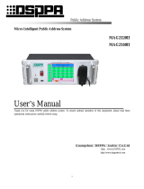
Public Address System
Digital Audio Matrix
M-808
User’s Manual
Welcome choosing our Public Address System! Please read the Instructions carefully before operating this device.
LY International Electronics Co., Ltd
http://www.lyintlcorp.com/

M-808 - V0.3
Facture 2017-07-26
About the Instructions
The Instructions is used at the date when the digital audio matrix M-808 device is developed. It
contains system introduction, operation attentions, system connection instructions, product instructions
and other contents of the digital audio matrix M-808 device. The user shall read the Instructions
carefully and operate the device following the indications in the Instructions before the installation and
operation of the device.
Any symbol marked on the rear panel of this machine must be noted. The operations must be
performed according to the instructions of these symbols.
Please keep the Instructions for future reference!

WARNING
Be sure to observe the following cautions to prevent the damage to the users and others, and the
damage to the equipment or property!
This symbol means a “prohibition”. This symbol means a “must”.
Check the damage condition of power cord.
Do not pulling the power cord to unplug the plug,
unplug the plug directly; otherwise it may cause
electric shock, short circuit or fire.
Do not block the air vent during the operation.
All air vents must be unblocked to avoid the
overheating.
Do not expose the device to dust, vibration,
extreme cold and hot environment.
Do not place heavy objects on the device. Do not
impose an excessive force when operating the
switch, buttons or connecting the external audio
equipment.
Avoid any foreign matter (paper, metal, etc.)
from entering the device through gap or opening.
In such a case, please power off this device
immediately.
Do not attempt to detach the internal parts of this
device or remold it by any way.
Please unplug the power plug immediately to
avoid the electric shock, fire or other accident and
professionals shall be invited for maintenance of
the device in case of any sudden sound
interruption, any abnormal smell or smoke during
the running of the machine.
Smell of Scorching
Be sure to unplug the AC power cord or turn off
the wall outlet to achieve zero energy consumption
when this device will not be operated for a long time.

* * TABLE OF CONTENTS
CONTENTS
A. PRODUCT DESCRIPTION ................................................................................................................................. 1
1.1 PERFORMANCE ................................................................................................................................................ 1
B. APPEARANCE DESCRIPTION .......................................................................................................................... 2
2.1 DESCRIPTION OF FRONT PANEL .................................................................................................................. 2
2.2 DESCRIPTION OF REAR PANEL..................................................................................................................... 3
C. INSTALLATION INSTRUCTION ....................................................................................................................... 5
3.1 INSTALLATION IN PHONE .............................................................................................................................. 5
3.2 INSTALLATION IN PC....................................................................................................................................... 5
D. OPERATING GUIDE ........................................................................................................................................... 5
4.1 LINKAGE INSTRUCTION................................................................................................................................. 5
4.1.1 PHONE ............................................................................................................................................................. 5
4.1.2 PC ................................................................................................................................................................... 6
4.2 INTERFACE INSTRUCTION ............................................................................................................................ 7
4.2.1 DESCRIPTION OF MAIN INTERFACE .................................................................................................................... 7
4.2.2 DESCRIPTION OF PHONE INTERFACE ................................................................................................................ 14
4.2.3 DESCRIPTION OF PC INTERFACE ...................................................................................................................... 19
PACKING LIST ....................................................................................................................................................... 26
SPECIFICATION .................................................................................................................................................... 26

* * TABLE OF CONTENTS
1
A. Product Description
1.1 Performance
7″with touch capacitive color screen, embedded operating system;
Built-in high performance DSP, 10M/100M/1000M Ethernet interface;
Integrated Digital Audio Matrix, display, intelligent timing control, zones control and other functions in PA
system;
8-channel zones output independent control and each channel with individual icon equalizer and individual
volume control;
Each channel can be linked independently with control panel and remote volume control of sound source
with voice, wiring and MP3 player;
8-channel normal sound source balanced input and each channel with individual icon equalizer and
individual volume control;
2-channel local microphone input(with phantom power options) and each channel with individual icon
equalizer and individual volume control;
1-channel MP3 display(built-in program or extrapolated U disk) with individual icon equalizer and
individual volume control;
1-channel DM with individual icon equalizer and individual volume control;
1-channel fixed telephone input(with authority management), only one line can be operated in the whole area
and with individual volume control;
1-channel chime with individual volume control;
1-channel voice alarm(a key alarm), can be replaced alarm contents as needed;
4-channel remote paging microphone, parallel paging with priority control and individual icon equalizer and
individual volume control;
1-channel fire emergency analog signal input;
8-channel independent zones fire emergency trigger input(short circuit signal), 1-channel whole area fire
emergency trigger input(short circuit signal), 1-channel fire linkage input(short circuit signal);
Support PC/Android LAN remote control;
zones and sound source physical shortcuts, easy to use;
Built-in zones monitoring;
Built-in 8G storage and maximum support 32G;
Support AC220(or 110V) & 24V DC power supply.

* * TABLE OF CONTENTS
2
B. Appearance Description
2.1 Description of Front Panel
1. 1-8 zones button and indicator
2. Display/Touch Screen
The display shows dynamically all information of the system and it is also the touch screen for operation.
3. Page all button and indicator
4. Background source button and indicator
5. Full emergency button and indicator
It can send the warning signals to all zones simultaneously by pressing the full-warning button of the system,
and meanwhile, the indicator light is ON.
6. Chime and indicator
7. Power
8. USB
Use to connect the U disk with MPS programs, mobile hard disk and other memory devices. It can directly
play the songs of the U disk and copy the programs for built-in MP3 player.
9. All-page close and indicator
10. All-page open and indicator
11. Volume control -
12. It controls the volume of zones. Press this button to turn down the volume
It controls the volume of zones. Press this button to turn up the volume

* * TABLE OF CONTENTS
3
2.2 Description of Rear Panel
WP1 WP2 WP3 WP4 WP5 WP6 WP7 WP8
PAGE1 PAGE2 PAGE3 PAGE4
LINE INPUT
+-G+-G+-G
+-G+-G+-G+-G
1 2 3 4 5 6
+-G+-G
7 8
PHANTOM
MIC
MIC 1 MIC 2
MIC INPUT
TEST
DC POWER INPUT
GND.+24VDC
EMERGENCY
EVAC_IN
ALERT_IN
GND
RESERVE
RESERVE
1G
CONTACT CLOSURE
FIRE ALARM TEST
NET
MODEL: MAG808
VOLTAGE SELECTOR
~110V/50Hz F4AL
~220V/50Hz F2AL
110V
220V
TEL
USB
ZONE OUTPUT
+-G
+-G+-G+-G+-G+-G+-G
3 4 5 6 7 8
+-G
+-G
2
+-G
+-G
1
FM
~110V/220V 50Hz
F4AL
2345678
RESERVE
VOL
PHANTOM
MIC
VOL
RISK OF ELECTRIC SHOCK
DO NOT OPEN
CAUTION!
MP3
VOL
EMC_IN-
EMC_IN+
RESERVE
230
12
13
14
15
16
17
18
12345678910 11
① AC 110V/220V Selector Switch
Use to select the operating voltage.
② AC Power Input Socket
Plug the AC power cord into this socket.
③ DC 24V connection terminal
Externally connect with DC 24V power supply.
④ DC 24V Fuse
Use for the fixed DC power supply. If it is fused, please replace it with the fuse of the same specification. A
continuous fusing indicates that there are some faults.
⑤ MP3 volume control knob
⑥ FM Antenna Interface
⑦ zones Output
Connect with the power amplifier.
⑧ Network Interface
It is used to connect the LAN, through which the remote control of the system is performed.
⑨ Alarm Signal Input
Input the signals from the fire control center.
⑩ Alarm Signal Input
⑪ Testing Interface
It is used for testing.

* * TABLE OF CONTENTS
4
⑫ Telephone Interface
It is used to connect the telecom signals to this machine.
⑬ USB
It is used to update the applications.
⑭ MIC2 Input Interface
⑮ +48V Phantom Power Control Switch (MIC1-MIC2)
MIC1 and MIC2 are individually controlled. Turn left the switch to open this power source when the +48V
phantom power supply microphone is used.
⑯ Volume Control Knob
⑰ Line Input Interface
⑱ As shown below:
WP1 WP2 WP3 WP4 WP5 WP6 WP7 WP8
PAGE1 PAGE2 PAGE3 PAGE4
2
1
3
TEST
① Control panel interface
Connect 8 sets M-808C/M-808S control panels.
② Extension interface
③ Connect 4 M-808R paging microphones

* * TABLE OF CONTENTS
5
C. Installation Instruction
3.1 Installation in phone
Double-click to install the APP, according to the instructions to install.
3.2 Installation in PC
Click the software to open the software page.
D. Operating Guide
4.1 Linkage Instruction
4.1.1 Phone
1. First connect the M-808 host device;
2. Connect the host device to LAN;
3. Connect the desired Android phone to the WIFI in the LAN where the host device is connected and set the
static IP address of the phone. The static IP address should be in the same network segment with the IP address of
the host device (e.g the host device IP is: 192.168.8.220, the static IP address of the phone should
be :192.168.8.100.):As shown below:
4. Enter the software connection interface and input the host's IP address and port number. As shown below:

* * TABLE OF CONTENTS
6
4.1.2 PC
1. First connect the M-808 host device;
2. Connect the host device and PC to LAN;
3. Set the IP address of PC and host device in the same network segment (e.g the host device IP is:192.168.0.220,
the PC IP should be 192.168.0.10.): As shown below:
4. Enter the software connection interface and input the host’s IP address and port number. As shown below:

* * TABLE OF CONTENTS
7
4.2 Interface Instruction
4.2.1 Description of Main Interface
After turning on the power switch, the device is started and it enters the following main interface. In this
interface, various operations as shown in the following chart are available.
Main Interface Chart
(1) Player Interface
In the following interface, the list box on the left is the directory list of built-in player and the list of songs
under this directory. Through the operating buttons of MP3, the operations of Play, Stop, Previous Song, Next
Song and Playback modes can be available. On the right of the interface, it is the audio interface. It can achieve
the multi-channel operations of automatically searching and playing the channel, playing the previous
channel/next channel, playing the specified channel, collecting the channels, etc.
Zone
switch
Slide the scroll bar
to control the
volume
You can click this
option to control
the volume. Each
click will increase
the volume of five
numbers.
Automatic (allows
timing reminder) /
manual (timing
reminder off)
Volume control of
the
whole area
Switch of the
whole area
After the area operation on the screen, click the
button to restore the partition state to the state
before the operation. Note: If the whole
operation after a single partition operation, it
will not be restored.
Audio
Selection
Full partition
sound source
settings

* * TABLE OF CONTENTS
8
Player Interface
(2) Zone Settings
As shown below, each zone can be equalized. During the operation, it is necessary to open the switch of
equalizer to adjust the equilibrium.
Interface of Zone Settings
(3) Sound Source Settings
As shown below, each sound source can be equalized and the volume can be set. During the operation, it
is necessary to open the switch of equalizer to adjust the equilibrium.
Playback Modes:
1. Sequence
2. Loop
3. Shuffle
4. Single Loop
FM setting area
List:
1.Pop Music
2.Classical
Music
3.Background
Music
4.Sport Music
5.Chime
6.Other
Play
status/Play
tentative
status

* * TABLE OF CONTENTS
9
Interface of Sound Source Settings
(4) Monitoring Interface
As shown below, only one zone can be monitored each time. When the background color of zone button
becomes blue, it indicates this zone is monitored. When this zone will not be monitored, it can be canceled by
clicking the key “Cancel” on the right of this interface. The volume size of the monitoring object can also be
controlled.
Monitoring Interface
(5) Setting Interface
You can set up all information of the entire system in this interface. You can set up all items in this interface
before you perform the operations like Play in the main interface, and various items of the system can then be

* * TABLE OF CONTENTS
10
accurately executed and operated.
Setting Interface
1) Network Setting
Click the button “Network Setting” to enter the IP address setting interface. As shown below, there are ID
address setting and the current IP address information of this machine in this interface. After the IP address is set
up, click the button OK. The newly configured IP address cannot be effective unless the device is re-started.
Interface of Network Setting

* * TABLE OF CONTENTS
11
2) Date and Time Setting
Please align the current clock when setting the system time, which relates to the implementation punctuality
of timing point. The timing point can be accurate to seconds. So, when re-setting the system time, please pay
attention to the setting of seconds.
Interface of Date and Time Setting
3) File Management
In this setting, you can copy the sound source of this machine to U disk or copy it from U disk to this
machine. During the operation, you shall select the sound source and direction to be copied,(or selected all) and
then click the button “Copy”.
Interface of File Management

* * TABLE OF CONTENTS
12
4) Timing Point Setting
Create the timing point: select the button “Create” to set up the Start Time and Stop Time, select the Day of
Week, Zone and Sound Source, and then click the button “Save” to add the timing point. And the created timing
point can be deleted, edit, zones setting, ring and other operations. As shown below:
Interface of Timing Setting
5) Password Setting
The password setting is mainly for the phone calls. When there is a phone call access, it can be
answered only by entering the password. The password can only be set up to four numbers.
Timing
point
list
Start and Stop
Time
Date
Only can select the first
and tail timing point
Create timing point Delete selected/all timing
point
Copy
timing point
Time/Zone/Media setting
Return to upper
level

* * TABLE OF CONTENTS
13
Interface of Code Setting
6) Other Settings
As shown below, you can set up four setting items, namely, input for BGM (background music), input for
PAGE ALL, other input volume set and priority.
Interface of Other Settings
7) Control Terminal
In this interface, you can view the ID number, IP address and controlled zones and other information of
the control terminal in the system.

* * TABLE OF CONTENTS
14
Interface of Control Terminal
4.2.2 Description of Phone interface
According to the operation of the phone terminal connection instructions, enter the main surface when the
connection is successful, and can operate various operations in the interface which is as shown below.
Main Interface Chart
Main interface
Paging
switch
Zones sound
source setting
Zones volume
control
Full partition
sound source
setting Full partition
switch
After the area operation on the
screen, click the button to restore the
partition state to the state before the
previous operation. Note: The
volume control area does not follow
the previous operation state
Volume
input area
Full partition
volume control
Auto:timer available,
set timing reminded
automatically;Manual:
timer not available
Slide the scroll
bar to control
the volume

* * TABLE OF CONTENTS
15
(1) Player Interface
In the following interface, you can operate basic operations like sorting and playing the songs.
On the right of the interface, it is the audio interface. It can achieve the multi-channel operations of
automatically searching the frequency, playing the audio, playing the previous channel/next channel,
playing the specified channel, collecting the channels, etc.
Player interface
(2) Zone Settings
As shown below, each zone can be equalized. During the operation, it is necessary to open the switch of
equalizer to adjust the equilibrium.
Interface of Zone Setting
(3) Sound Source Settings
As shown below, each sound source of control panel device can be equalized and the volume can be set.
During the operation, it is necessary to open the switch of equalizer to adjust the equilibrium.
Player interface
List:
1.Pop Music
2.Classical
Music
3.Background
Music
4.Sport Music
5.Chime
6.Other
Can sort music.
File List
FM setting
area
Store List
Search
Store/Cancel store
FM reception
program,
FM0.1 Hz
Previous/Next
program
Current
mode:Sequence
Playback Modes:
1. Sequence
2. Loop
3. Shuffle
4. Single Loop
Previous piece
Play
Stop
Next
piece
Zone select
Equalizer
switch
Volume control
by sliding

* * TABLE OF CONTENTS
16
Interface of Sound Source Setting
(4) Monitoring Interface
As shown below, only one zone can be monitored each time. When the background color of zone button
becomes blue, it indicates this zone is monitored. When this zone will not be monitored, it can be canceled by
clicking the key “Cancel” on the right of this interface. The volume size of the monitoring object can also be
controlled.
Monitoring Interface
Control panel
device select
Equalizer
switch
Volume control
by sliding
/