Page is loading ...

Products manufactured and sold by OMEGA RESEARCH & DEVELOPMENT, INC. (the Company), are
warranted to be free from defects in materials and workmanship under normal use. If a product sold
by the Company proves to be defective, the Company will repair or replace it free of charge within
the first year and thereafter all parts to be repaired will be free with only a nominal charge for Omega
Research and Development, Inc.'s labor and return shipping, to the original owner during the lifetime
of the car in which it was originally installed.
All products for warranty repair must be sent postage prepaid to Omega Research & Development,
Inc., P.O. Box 508, Douglasville, Georgia 30133, with bill of sale or other dated proof of purchase. This
warranty is nontransferable and does not apply to any product damaged by accident, physical or
electrical misuse or abuse, improper installation, alteration, any use contrary to its intended function,
unauthorized service, fire, flood, lightning, or other acts of God.
This warranty limits the Company's liability to the repair or replacement of the product. The
Company shall not be responsible for removal and/or reinstallation charges, damage to or theft of the
vehicle or its contents, or any incidental or consequential damages caused by any failure or alleged
failure of the product to function properly. Under No Circumstances Should This Warranty, Or The
Product Covered By It, Be Construed As A Guarantee Or Insurance Policy Against Loss. The
Company neither assumes nor authorizes any person or organization to make any Warranties or
assume any liability in connection with the sale, installation, or use of this product.
LIMITED LIFETIME WARRANTY
This device complies with part 15 of the FCC Rules. Operation is subject to the following two conditions: (1) This device may not cause harmful
interference and, (2) This device must accept any interference received, including interference that may cause undesired operation.
The manufacturer is not responsible for any radio TV interference caused by unauthorized modifications to this equipment. Such modifications
could void the user’s authority to operate the equipment.
12//07 MA_MARS33+
One or more of these patents may apply to this product:
#5,612,669 #5,654,688 #5,663,704 #5,729,191 #5,818,329 #5,612,578 #5,739,747 #382,558 #385,878 #5,750,942 #5,739,748 #5,719,551
#406,107 #701,285 #5,973,592 #5,982,277 #5,986,571 #6,011,460 #6,037,859 #6,049,268 #6,130,605 #6,130,606 #6,140,938 #6,140,939
#6,150,926 #6,144,315 #6,184,780 #6,188,326 #6,243,004 #6,249,216 #6,275,147 #6,297,731 #6,320,514 #6,320,498 #6,346,876 #6,346,877
#6,366,198 #6,392,534 #6,429,768 #6,433,677 #6,480,095 #6,480,117 #6,480,098 Foreign Patent #199700312 #EP0817734B1
#98906445.6 #2,320,248 #701,285
VEHICLE SECURITY SYSTEM
with KEYLESS ENTRY & REMOTE STARTER
FOR AUTOMATIC TRANSMISSION VEHICLES ONLY
MARS-33+
OPERATING & INSTALLATION
INSTRUCTIONS
COPYRIGHT: OMEGA RESEARCH & DEVELOPMENT 2007

47
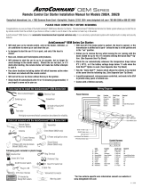
WIRING DIAGRAM OVERVIEW
Yellow/Green:
OEM Disarm
Yellow/Red:
OEM Arm
Gray:
Trunk Release
(page 39)
Black:
(-) Ground
10 Amp
Black/Yellow:
Red/Black:
Brake (+) YELLOW/RED = OEM ARM - OUTPUT
BLACK/YELLOW = ENGINE DETECT INPUT
RED/BLACK = BRAKE + INPUT
YELLOW/GREEN = OEM DISARM - OUTPUT
GRAY = TRUNK RELEASE - OUTPUT
BLUE = HOOD - INPUT
ORANGE = ANTI-GRIND - OUTPUT
PINK/BLACK = START ACTIVATION - INPUT
BROWN = HORN - OUTPUT
GREEN/RED = GLOW PLUG +/- INPUT
WHITE = PARKING LIGHT +/- OUTPUT
BLACK = CHASSIS GROUND
VIOLET = (+) DOOR TRIGGER INPUT
GREEN = (-) DOOR TRIGGER INPUT
DOORLOCK OUTPUT PORT (pages 40)
SATELLITE RELAY PORT (pages 31)
RED = +12V INPUT
YELLOW/GREEN = PROGRAMMABLE + OUTPUT
YELLOW = IGNITION + OUTPUT
RED = +12V INPUT
WHITE = ACCESSORY + OUTPUT
GREEN = STARTER + OUTPUT
Smart
Start
Adjust
PARKING LIGHT PROGRAM JUMPER (page 37)
GLOW PLUG PROGRAM JUMPER (page 35)
Tach
Wire
Adjust Adjustment
LED
SMART START /
TACH WIRE
Smart Start
Tach Wire
Program Jumper inside case below removable
door (page 31)
SWITCH
(Tach Wire)
To Coil (Smart Start)
To Battery +
?
Green:
(-) Door Violet:
(+) Door RECEIVER PORT
VALET SWITCH PORT
STATUS LIGHT PORT
Re-
ceiver
Unit
SENSOR PORT
Contents
Operation Guide
Introduction & Safety Considerations .........................................................................3
Basic Transmitter Functions Overview ................................................................4 & 5
The Receiver Unit ........................................................................................................6
Lock/Arm, Alarm Trigger, Prewarn, & Unlock/Disarm .............................................7-9
Remote Starting the Engine.................................................................................. 9-10
Remote Panic............................................................................................................11
Remote Trunk Release.............................................................................................12
Valet Mode and Alarm Override........................................................................... 12-14
Programming Features....................................................................................... 14-17
About the Programmable Features .................................................................... 17-23
Programming Transmitters ................................................................................ 23-25
Other Operational Notes ..................................................................................... 25-26
Limited Lifetime Warranty .......................................................................... Back Cover
Installation Instructions
Installation Considerations, Cautions and Warnings................................................. 27
Main & Receiver Modules.....................................................................................28-29
Wiring Diagram Overview .....................................................................................46-47
6 Wire Main Harness ............................................................................................29-31
3 Wire Connector ..................................................................................................31-32
14 Wire Harness ...................................................................................................32-40
2 Wire Connector ..................................................................................................40-45
2

Parking Lights
Light Switch
Switch
Ignition
OPTIONAL
Relay For
Starter Kill /
Anti-Grind
White: Parking
Light Output
Green:
Starter (+) White:
Accessory (+)
Yellow:
Ignition (+)
Orange: (-) Output
When
Activated
Green/Red:
Glow Plug Input
(page 35)
Pink/
Black:
(-) Start
Activation
Blue:
(-)
Hood
Switch
Hood Pin
Switch
Brown:
Siren or
Horn Output
(page 39)
Red & Red:
(+) 12 Volts
Starter
30 Amp
Battery
++
++
+
30 Amp
Yellow/
Green:
Programmable
Output
(page 30)
46 Congratulations for choosing the Modular Advanced Remote Starter . The MARS offers the
security of an antitheft alarm, the convenience of keyless entry, and the luxury of starting
your vehicle's engine from the comfort of your home or office.
Introduction
It is highly recommended that this system be professionally installed, as the sophistica-
tion of the modern automobile and the complexity of this type of product installation is
often beyond the abilities of most do-it-yourselfers.
The MARS-33+ includes one 1-way transmitters and one 2-way controller which can
operate the system.
3
Safety Considerations
The MARS is a very flexible system. It has capabilities and features which may or may not
be utilized in your installation. It also has many programmable features which can affect its
operation. While these are explained as thoroughly as possible in this guide, your Omega
dealer or installer is the best source for information about your system.
•This unit is for vehicles with an automatic transmission only. Installation in a vehicle
equipped with a manual transmission can result in property damage or personal injury.
•This unit is for fuel injected gasoline or diesel engines.
•Children should not be left unattended in, or be allowed to play with the activating Trans-
mitter or Controller of any remote starter equipped vehicle.
•Do not use the remote starter feature in an enclosed garage or other structure.

Reversing Polarity System
Using External
Relays
Unlock
Lock
Unlock
Lock
Blue Wire
Green
Wire
Doorlock Actuators
Master Doorlock
Switch
85
86
87a
87
Coil
30
85
86
87a
87
Coil
30
++
++
Secondary Doorlock
Switch
Control
Module
+
+
+
+
45
The 1-Way Transmitter has four push but-
tons. Pressing and releasing these but-
tons will operate the system as shown.
Pressing and holding the Lock
or Unlock buttons will activate the
system’s remote panic feature.
Another press stops it.The Blue
indicator lights when ever one of
the Transmitter buttons is pressed.
When the light is dim, or range is
reduced, replace the Transmitter’s
battery by removing the small phillips
screw on back, and installing a fresh 12
volt “23A” battery.
1-Way Transmitter Functions
4
“Lock”
Button
“Start”
Button
Blue
“Transmit light”
“Unlock”
Button
“Trunk”
Button
See page 5 for infor-
mation on upgrading
your MARS system to
2-way operation!

This power doorlock system differs from the negative and positive pulse systems in that there
is no doorlock control unit or relays. In this type of system, the switches themselves supply the
positive voltage directly to the doorlock actuators, and, more importantly, provide the return
ground path. It is important to note that the lock and unlock wires in this system actually rest
at chassis ground. This means that both the lock and unlock wires must be "opened", or cut,
to make the proper connections.
Examine the wires on the back of the switch. (Normally 5 wires will be found
1) One wire will show +12 Volts, regardless of the switch's position.
2) Two wires will be grounded regardless of the switch's position.
3) One wire will show +12 Volts only when the switch is pushed to "Lock".
4) One wire will show +12 Volts only when the switch is pushed to "Unlock".
- When the lock /unlock wires are found, they must be cut one at a time. If the correct wires
are cut the door locking system should not operate from the primary switch.
- Notice that in the diagram the driver's switch is the primary or “Master” switch (in some
vehicles, the primary switch is on the passenger's side). The half of the cut wires which come
from this primary switch are referred to as the "Switch" side. The half of the cut wires which
go to the secondary switch are referred to as the "Motor" side even though the cut is made
between the switches.
the wires show partial ground through the relay’s coils.
2) The doorlock switch in a Reversing system will have 5 wires, while a Positive
pulse system the switch will have 3 wires.
3) A Positive pulse system uses factory relays or a control unit, a Reversing system does
not. 5 Wire Reversing Polarity Systems
44 2-Way Controller Functions
The optional 2-Way Control-
ler has the same four sys-
tem-operating push buttons
as the Transmitter. Their
use is also identical, as
shown.
While the Controller’s Blue
“transmit” light is the same
as the Transmitter’s, the
Controller adds more indica-
tor lights, and a beeper.
These items inform the user,
by sight and sound, of op-
eration confirmations and
notifications of events from
the system.
The Controller
also has the A/B switch, for op-
erating a second MARS sys-
tem. Its battery is a “AAA” pen-
light battery, and is accessed
by sliding the lock tab, then
battery door, from the rear of
the Controller. When the
“Trunk”
Button
Red
“Unlock”
Light
Orange &
Green
“Starting”
& “Trunk”
Light
Blue “Transmit”
Light
“Start”
Button
“A/B Switch”
for multi-car use
Green
“Unlock”
Light
“Lock
/ Arm”
Button
“Unlock /
Disarm”
Button
- Continued next page -
5

3) One wire will show +12 Volts only when the switch is pushed to "unlock".
Positive Pulse System Using External Relays
Blue Wire
Green
Wire
Doorlock
Switch
85
86
87a
87
Coil
30
85
86
87a
87
Coil
30
+
+
++
+Unlock
Lock
Control
Module
2-Wire Connector
Doorlock
Actuators
+
Vehicle's Doorlock
Relay Control Unit
Warning: The Positive pulse system can be confused with the 5-wire Reversing Polarity system. This
is because both systems show +12 Volt pulses on the “Lock” and “Unlock” wires when the vehicle’s
switch is pressed respectively. It is critical to identify which system is present, since if +12 Volts is pulsed
into a Reversing Polarity system, which rests at ground, a direct short circuit will occur.
3 main differences between a Positive pulse and a Reversing Polarity system:
1) In a Reversing system the Lock/Unlock wires rest at ground, while in a Positive system
43
The Receiver Unit is designed for mounting di-
rectly on the vehicles’ window glass, which also
gives the system its best operating range. Should
this not be possible or desired, the Receiver Unit
may be mounted in a hidden location, and provi-
sions are made for optional separately-mountable
Valet / Override Switch and Status Light.
The Receiver Unit
Valet / Override
Switch
Blue Status Lights
An important part of the MARS system is its Receiver Unit. As its name implies,
the Receiver Unit contains the radio receiver needed for the system to operate
from the hand-held Transmitter or Controller. The Receiver Unit also contains
the Valet / Override Switch and the Status Light. The switch is used to place the
system into Valet Mode (page 12) or to override the alarm if needed (page 14).
The Status Light (actually two) reflects system operations and conditions.
battery is low, when any button is pressed the 2-color LED will briefly and rapidly
flash green and orange immediately after the blue “transmit” LED lights.
The 2-Way Controller uses lights and audible chirps to indicate system events. If desired
the chirps may turned off, so that the Controller operates silently. Press the Lock and
Trunk buttons together to toggle the chirps on and off. When the Lock and Trunk buttons
are pressed, the blue light will light followed immediately by either the red light or the green
light. If the red light flashes the chirps are off; if the green light flashes the chirps are on.
Even if the MARS system confirmation chirps are turned off, the controller still has its
chirps, unless they, too, are turned off as described here.
6

Using the MARS
Operating the MARS system is easy, and basically the same processes when using the
1-way transmitter or the 2-Way Controller. When the optional 2-way Controller is used,
the system will respond back to the user confirming the operation. The Transmitter and
Controller both light their blue indicator light when transmitting a signal.
User’s action or event MARS ControllerMARS system in vehicle
Locking the Doors & Arming the Alarm
1 chirp; 1 red LED flash.Press LOCK button.
(Blue LED lights) Alarm arms, doors lock, 1 parking
light flash, siren chirps once. The
Receiver Unit Status Light flashes
fast, then slow indicating “Armed”.
3 long chirps; fast red LED flashes,
followed by periodic fast red flash.
- - NONE - - Parking lights flash, siren sounds. Re-
ceiver Unit Status Light changes from
slow to fast flash.
User’s action or event MARS ControllerMARS system in vehicle
Should the Armed Alarm Trigger
Locking the doors with either Transmitter and Controller secures the vehicle, AND arms
the MARS alarm unless the system is in Valet Mode (page 12). Whenever the alarm is
armed, the Status Light in the Receiver Unit will flash, as an indicator and a deterrent.
Should the system detect any violation of a protected zone it will trigger an alarm condition,
which sounds the siren and flashes the parking lights. If the Controller was used to arm the
MARS, the system will also send a signal to the Controller to notify the user.
( )
if
used
( )
if
used
7
operate the vehicle’s on-board doorlocking relays. If the vehicle’s Negative pulse
doorlocking system requires more than 500mA Negative output, optional relays must
be used.
This doorlock system is similar to the 3 wire negative pulse system except the doorlock
switches send +12 Volt pulses to operate the doorlock relays/control unit.
Examine the wires on the back of the doorlock switch:
1) One wire will show +12 Volts, regardless of the switch's position.
2) One wire will show +12 Volts only when the switch is pushed to "lock".
3 Wire Positive Pulse Systems
Negative Pulse System Using
Direct Connection
Green Wire To Switch
Door Lock Wire
Door Lock
Switch
Blue Wire To Switch
Door Unlock Wire
Vehicle's Doorlock
Relay Control Unit
Unlock
Lock
Control
Module
Ground
2-Wire Connector
Doorlock
Actuators
+
42

Whenever the alarm is armed, and including while it is triggered, an optional starter
interrupt can prevent the vehicle’s engine from being started. If the alarm is triggered,
and the user does not disarm it, it will stay triggered for 60 seconds and then automatically
reset back to the armed state, provided that none of the protected zones are violated at that
time. Should there still be a violated zone, the MARS will re-trigger an alarm, and resend
the notification to the pager. This can occur for up to 5 alarm cycles.
3 fast chirps; red LED flashes once.- - NONE - - Siren briefly sounds and parking lights
flash twice. (Alarm remains armed)
User’s action or event MARS ControllerMARS system in vehicle
Alarm Prewarning
The alarm also has a “Prewarning” feature. While it is armed, if the shock sensor part of
the system detects a light impact, the alarm will respond to make its presence known.
More aspects of the alarm operation follow, such as using the Valet / Override Switch.
2 chirps; 2 green LED flashes.Press UNLOCK button
(Blue LED lights) Alarm disarms, doors unlock, 2 park light
flashes then on 30 sec., siren chirps twice.
Also, when disarming and unlocking, if the alarm was triggered, and reset, including while it is
triggered, the system response and the Controller confirmation is different:
3 long chirps, with flashing red LED.Press UNLOCK button
(Blue LED lights) Alarm disarms, doors unlock, 2 park light
flashes, then 4 flashes, then on 30 sec.,
siren chirps twice, then 4 chirps.
User’s action or event MARS ControllerMARS system in vehicle
Unlocking the Doors & Disarming the Alarm
( )
if
used
( )
if
used
8 The Blue wire supplies a negative pulse for locking the
vehicle's doors. Programmable feature #12 changes the single unlock pulse to be a double
unlock pulse.
22 Gauge Blue Wire: 500mA ( - ) Unlock Output
Connection If Desired.
This harness, which plugs into the White 3-pin port on the control module, is the power
doorlock outputs by which the MARS operates the vehicle’s power doorlock system (the
vehicle must have existing power doorlocks). The doorlock interface needed to allow the
system to operate the doorlocks will depend upon the type of power doorlocking system
the vehicle is equipped with. The following sections describe typical power doorlocking
systems, which are categorized as “3 Wire Negative Pulse”; “3 Wire Positive Pulse”, and “5
Wire Reversing Polarity” systems.
This power doorlock system is simplest of all doorlocking systems. A Negative pulse
system will have only three wires at the doorlock switch.
Examine the wires on the back of the doorlock switch:
1) One wire will show Ground, regardless of the switch's position.
2) One wire will show Ground only when the switch is pushed to "Lock".
3) One wire will show Ground only when the switch is pushed to "Unlock".
The lock & unlock wires coming out of the switch operate the vehicle’s doorlock relays or a
control unit with on-board relays, therefore the lock & unlock wires will read Positive voltage,
up to +12 Volts, when the switch is at rest. The correct connection point is between the
switches and the relays. The Red connector's Green and Blue wires can be connected
directly to the vehicle’s Negative pulse system since only a Negative pulse is required to
3 Wire Negative Pulse Systems
41

Unlocking the doors with either Transmitter and Controller disarms the MARS
alarm, in addition to allowing access to the vehicle. If the alarm is disarmed
while it is triggered, the alarm will have the extra 4 chirps and parking light flashes, but the
Controller will not change to having the 3 chirp and red flashing LED confirmation until
after the alarm resets itself.
Should the Transmitter or Controller not be available (dead batteries or lost), an armed or
triggered MARS system may be disarmed by the user via the Valet Switch, but the vehicle’s
ignition key is needed (see page 14).
Remote Starting
User’s action,
then vehicle event MARS ControllerMARS system in vehicle
Makes a long chirp & 2-color LED
flashes rapidly green and orange
Press START button
(Blue LED lights) Parking lights turn on & siren chirps
3 times (if connected)
The MARS unit turns on the ignition and engages the starter. The parking lights turn
off. Chirps twice & the 2-color LED
slowly flashes green and orange
If the engine starts and
runs Parking lights turn back on
2-color LED continues to flashes
rapidly green and orange
If the engine won’t run Parking lights turn back on, then on
& off as the system re-attempts to
start the engine
Makes 4 chirps & 2-color LED
flashes orange 4 times
Parking lights turn off and stay off
When the engine turns off, if it is stopped, or if it does not start and run after several tries.
Upon entering the vehicle place the ignition key in the switch and turn it to the "On" posi-
( )
if
used
9
Wiring - 2 Wire (3 Cavity) Connector / Doorlock Port
22 Gauge Green Wire: 500mA ( - ) Lock Output
Connection If Desired. The Green wire supplies a negative pulse for locking the
vehicle's doors.
illuminates the interior light when any of the vehicle’s doors is opened. As a general
rule, “Negative” dome lights (Green wire) will have no voltage present and will also
show chassis ground when the doors are opened, and up to 12 volts when the doors are
closed. “Positive” dome lights (Violet wire) have 12 volts present when the doors are opened,
and chassis ground when the doors are closed.
Regardless of type, the correct target wire will show this polarity change when any door is
are opened. If the vehicle has delay dome lights, remember to take this into account when
testing the wire. If the pin switch is mounted in the metal structure of the vehicle, and the
dome light goes out when the switch is removed, suspect a grounding-type dome light
system. While the traditional pin switch is mounted in the front door jamb area, also be aware
that many vehicles utilize other types of switch devices to operate the interior lights. Some
have a sliding type of switch and many have the pin or sliding switches in the rear door jamb
area. In addition, some vehicles utilize switches in the doors, either connected to the exterior
door handles or to the latching mechanism. A vehicle which has the dome lights illuminating
when the exterior door handle is lifted is an example of this type of switching system. Also
be aware of vehicles which diode-isolate each door. Typically, this is usually encountered
with dash displays that indicate individual doors being ajar. The proper wire to connect to in
this type of system is the common wire which is routed to the dome light itself.
40

tion, and then deactivate the MARS. Do not turn the key to the "Start" position!
Deactivation
•Stepping on the brake pedal will turn the engine off.
•To stop the engine by remote control, simply press the “Start” button again.
•After the preset programmable time the MARS will automatically turn the engine off.
•Opening the hood will turn the engine off. If the hood is open when an activation attempt
is made, the MARS will not start the engine (see “Safety Circuits” below).
•Pressing the Valet Switch will also stop the engine.
When you leave your vehicle, simply set the climate controls for what you would like to
have operating upon remote starting - the heater, defroster or air conditioning.
User’s action or event MARS ControllerMARS system in vehicle
Violated Safety Circuit Prevents Remote Starting
2-color LED flashes orange 4 times
& has 4 chirps
Press START button
(Blue LED lights) Park lights flash 4 times, horn chirps
4 times (if connected); NO START-
ING ATTEMPT WILL BE MADE
Remote starting can be used in conjunction with the alarm operation, but remote start will
not operate when the system is in Valet Mode (page 12).
( )
if
used
10 The Gray wire has a 500mA Negative output
which is operated by the transmitter button with the “open trunk” icon, and this output is
designed for trunk release. In most cases, an optional external relay will be needed.
20-Gauge Gray Wire: ( - ) Trunk Release Output
Connection If Desired.
20-Gauge Green Wire: ( - ) Door Trigger Input
20-Gauge Violet Wire: ( + ) Door Trigger Input
Connection of One Recommended. One of these must be used so that the MARS
can detect an opening door, and trigger an alarm when it is armed. The Green wire is an
"open door" input for vehicles having Negative switching door pin switches, and the Violet
wire is an open door input to the control module for vehicles having Positive 12 volt door pin
switches.
Determine which of these two wires is appropriate and connect it to the vehicle wire which
The Brown wire is a Negative output designed to
sound the electronic siren or the vehicle’s horn for the alarm and remote “panic” features,
and for audible operation confirmations. Connect the Brown wire directly to the siren’s
black wire, and connect the siren’s Red wire directly to constant (+) 12 volts power.
If using the existing vehicle horn is preferred over the siren, the Brown wire may be
connected directly to the vehicle's horn switch wire, provided that the circuit operates with
(-) Negative 1/2 Amp of current or less. The horn wire is typically found around the steering
column; the correct wire will show Positive 12 Volts normally, and no voltage when the horn
is being sounded.
20-Gauge Brown Wire: ( - ) Siren or Horn Output
Connection Recommended.
39

Caution: When such a wire is located, be sure to also test that it is non-rheostated:
While metering the wire, operate the dash light dimmer control. The correct wire
will show no change in voltage when the dimmer is operated. Some vehicles have a
parking-light relay which is triggered by a Negative signal from the headlight switch. In
these vehicles, the White wire must be connected after the relay, usually at the Fuse/
Junction Block. Do NOT connect the White wire directly to the vehicle’s headlights. An
external relay is required. Vehicles having a split parking
light system must be diode-isolated,
with two IN4006 diodes as shown:
The function of the Orange wire is to provide a 500mA Nega-
tive auxiliary output which may be used to operate a starter motor "Anti-Grind" relay, which
prevents accidental starter grind should the key be turned while the remote starter is in
operation. Additionally, the Orange wire also provides the vehicle immobilizing feature for
the Anti-Carjacking operation. Connection instructions are included with optional starter
interrupt socket and relay.
20-Gauge Orange Wire: ( - ) Anti-Grind Output
Connection If Desired.
38
Right Side Circuit
White Wire
Light
Switch
Left Side Circuit
Parking Lights
Diode Isolation Of Split
Parking Light Systems
Two IN4006 Diodes.
Control
Module
User’s action or event MARS ControllerMARS system in vehicle
Activating Remote Panic
1 chirp & 1 red LED flash; then 2-
color LED flashes green once then
orange for 3 seconds, three times
Press LOCK button for 3
sec. (Blue LED lights) Doors lock, parking lights flash &
siren sounds (if connected)
2 chirps & 2 green LED flashes;
then 2-color LED flashes green
once then orange for 3 seconds,
three times
Press UNLOCK button for
3 sec. (Blue LED lights) Doors unlock, parking light flash &
siren sounds (if connected)
OR
Turning Off Remote Panic
1 chirp & 1 red LED flashPress LOCK button
(Blue LED lights) Doors lock, parking lights stop flash-
ing & siren stops sounding (if con-
nected) 2 chirps & 2 green LED flashes
Press UNLOCK button
(Blue LED lights) Doors unlock, parking lights stop
flashing & siren stops sounding (if
connected)
OR
Remote Panic may be activated in threatening situations, and it is enhanced by allowing
user choice of locking OR unlocking the doors, upon activation and deactivation. Remote
Panic will automatically stop after 60 seconds.
If Remote Panic is activated while the MARS system is in Valet Mode, the controller’s door
lock or unlock LED changes to 4 flashes, and it has 4 chirps. Remote Panic’s horn opera-
tion is also removed when the system is in Valet Mode.
( )
if
used
11

2-color LED lights green for 3 sec-
onds, then 2 chirps & 2 green LED
flashes
Press TRUNK button for 2
sec. (Blue LED lights) Trunk releases, doors unlock, 2 park
light flashes then on 30 sec., siren
chirps twice
The above is with the “out-of-box” operation of the MARS system. Trunk release confirma-
tion chirps cannot be turned off in the MARS system (only the doorlocking functions chirps).
If the MARS system is programmed to NOT unlock the doors when Trunk Release
is used, then the operation is:
2-color LED lights green for 3
seconds
Press TRUNK button for 2
sec. (Blue LED lights) Trunk release only occurs
User’s action or event MARS ControllerMARS system in vehicle
Remote Trunk Release
The Valet Switch: Valet Mode and Alarm Override
The MARS has a trunk release output. For Remote Trunk Release to operate, it must be
connected in the vehicle to operate, and optional parts may be required.
The MARS system has a “Valet Switch”, built into the window-mounted receiver unit, which
serves two important functions:
• To place the system into a “Valet Mode” whereby the alarm cannot be armed, nor can the
remote start function operate. Door lock, unlock and trunk release will still operate.
• To “Override” the alarm function, in conjunction with the ignition key, should the Transmit-
ter or Controller be lost or have a low battery.
( )
if
used
12 the engine.
The Pink/Black wire can be connected to an available auxiliary output of an
existing Remote Security System, and the unit's remote control may also be used to acti-
vate the remote start operation.
Dash Board
Lights Control
Module
Parking Lights
Light
Switch
White Wire
Typical Parking Lights Connection
Dimmer
Note: output
polarity is
selectable
Jumper
Parking Lights
The White wire is a programmable output to the
vehicle’s exterior parking lights to visually confirm system operations; +12 Volt or - Nega-
tive output may be selected by the Black jumper next to the doorlock port. Connect the
White wire to the vehicle's 12 Volt parking light circuit as shown in the accompanying
diagrams. The correct wire will show 12 Volts only when the headlight switch is in the
"Parking Light" and "Head Light" positions. This wire can usually be found at the head-
light switch, and various other locations within the vehicle, such as the rear body harness
or firewall connector.
18-Gauge White Wire: ( +/- ) Parking Light Output
Connection Recommended.
37

wire can usually be located in the vehicle in either kick panel area, in the wiring
harness which is routed into the cab from the door. The Yellow/Green wire has a
-Ground pulse whenever the MARS has an unlock output or its remote start operation is
activated.
20-Gauge Yellow/Red Wire: ( - ) OEM Arm Output
Connection If Needed. This output may be used to arm a factory-installed alarm, or,
if the vehicle is equipped with a Retained Accessory Power circuit, this output can be used
to “spike” the door pin switch wire, which will turn off the Retained Accessory Power circuit.
To arm a factory alarm after remote start engine run stops, connect the Yellow/Red wire
to the vehicle's factory arm wire. This wire will show Negative polarity when a key is held in
the "lock" position in the door key cylinder. This wire can usually be located in either kick
panel, in the wiring harness from the door, as it is routed between the door key cylinder and
the factory alarm.
To use this wire to turn off Retained Accessory Power, locate a vehicle wire within the
door or doorjamb which shows Negative when the door is open. Should such a wire be
found which is positive, a relay is needed to reverse the Yellow/Red wire’s Negative output
to Positive. The Yellow/Red wire produces a Negative pulse output whenever the system
turns off the engine after it has been remotely started.
20-Gauge Pink/Black Wire: ( - ) Start Activation Input
Connection If Needed. The Pink/Black wire allows for alternative devices such as an
existing keyless entry or alarm system to activate the remote start operation. If the Pink/
Black wire receives a Negative pulse, the MARS unit will start the vehicle's engine, pro-
vided that all safety circuits are in the proper status. After the engine has been started by
remote control, another Negative pulse on the Pink wire will turn the unit off, stopping
36
4 chirps; 4 red LED flashes
Press LOCK button
(Blue LED lights) Doors lock, 1 parking light flash,
siren chirps once.
4 chirps; 4 green LED flashes
Press UNLOCK button
(Blue LED lights) Doors unlock, 2 park light flashes then
on 30 sec., siren chirps twice.
Locking & Unlocking the Doors, System in Valet Mode
Trunk Release in Valet Mode
If the MARS system is programmed to NOT unlock the doors with Trunk Release,
the 2 green LED (unlock light) and final 2 chirps will not occur.
2-color LED flashes green 4 times
& has 4 chirps; then 2 green LED
flashes & 2 chirps (unlock indica-
tor)
Press TRUNK button for 2
sec. (Blue LED lights) Trunk release, doors unlock, 2 park
light flashes then on 30 sec., horn
chirps twice (if connected)
Remote Starting in Valet Mode
2-color LED flashes orange 4 times
& has 4 chirps
Press START button
(Blue LED lights) Park lights flash 4 times, horn chirps
4 times (if connected); NO START-
ING ATTEMPT WILL BE MADE
User’s action or event MARS ControllerMARS system in vehicle
To place the system into Valet Mode: At any time that the system is not armed
or triggered, simply press the Valet Switch for 5 seconds; the Status Light within the
Receiver Unit will light steady, to indicate Valet Mode, and stay illuminated continuously
while the system is in Valet Mode. The Status Light will continue to remain on solid, indi-
cating Valet Mode, until it is removed from Valet Mode (see next page).
Valet Mode changes the system and Controller operations as follows:
The alarm will NOT arm.
( )
used
if
13

The MARS has a total of 14 “programmable features”; most of these are “operational”
features, some are “installation”-related, and one returns all features to the factory setting.
These features can be changed by very easily by placing the MARS into a “Features Pro-
gramming Mode” and selecting features with the Valet Switch, and then using the Trans-
mitter/Controller buttons to set the feature as desired. The following chart shows the
Programmable Features, after which are detailed step-by-step programming instructions.
Programming Features
To turn off Valet Mode, simply press the Valet Switch until the Status Light turns off.
To Override the armed alarm: Use the key to turn the vehicle ignition switch “on”, and
within 5 seconds press the Valet Switch 1 time (the default setting), or press it the number
of time that the Coded Override has been programmed for.
Be prepared, as upon entering the vehicle, or upon turning on the ignition, the armed alarm
will trigger, sounding the siren and flashing the parking lights.
After pressing the Valet Switch, the alarm will disarm several seconds later if the entry was
correct. It will not disarm if the Valet Switch was pressed an incorrect number of times.
The factory-set default setting is 1 press to obtain the alarm override, but this is a program-
mable feature in which can the user can customize a number of 1 to 9 presses of Valet
Switch to achieve the override.
The Override procedure is also with the two forms of Anti-Carjacking protection. How to
custom-program the Coded Override is on page 18, and see page 20 for the description of
the Anti-Carjacking features.
14 read 1 to 6 volts AC with the engine idling, and will increase with engine speed.
2) Switch the selector slide switch on the MARS control module to the right toward
the 12-pin secondary harness (see pages 46-47 & the markings on the control module).
3) Adjust the tach signal by starting the engine and turning the right adjustment screw on
the control module slowly clockwise until the indicator LED lights solid.
4) Test the operation by remote starting and checking that the indicator LED slights solid.
The starter engagement is long enough for the engine to start, but without grinding. If
needed adjust the crank time by turning the adjustment screw clockwise for more signal
sensitivity and counterclockwise for less.
20-Gauge Yellow/Green Wire: ( - ) OEM Disarm Output
Connection If Needed. If needed, the Yellow/Green wire allows the MARS to disarm a
factory alarm system. Connect the Yellow/Green wire to the wire in the vehicle which is
connected to one of the doorlock key cylinders. The typical OEM alarm has an electrical
switch in the key cylinders which switches -Ground when the key unlocks the door. This
20-Gauge Green/Red Wire: ( +/- ) Glow Plug Input
Connection If Needed. The Green/Red wire allows the MARS to be used with diesel
engines, operates only if programmed (feature #13) and is also polarity-programmable.
Connect the Green/Red wire to the wire in the vehicle which powers the glow plugs, or the
wire which illuminates the “Wait To Start” light on the instrument panel. When connected,
the unit will not engage the starter if the Green/Red wire has +12 Volts; in other words,
using this wire simply delays the unit’s engagement of the starter. If the “Wait To Start”
light in the vehicle has a Negative switching circuit, change the position of the White “Glow
Plug +/- Select” Jumper on the module to reverse the Green/Red wire’s polarity input.
35

Each of these Programmable Features is explained in the following pages
15
cess. Consider both methods before selecting one to use, and then connect the
Black/Yellow wire accordingly. Either connection method must be performed at
the completion of the installation, after all other wiring connections are made.
Smart Start sensing is more commonly used, for its ease of installation. The unit as
received has Smart Start selected. Smart Start “reads” the vehicle’s battery voltage level
via the Black/Yellow wire to determine engine running status. To use Smart Start:
1) Connect the Black/Yellow wire to constant “Battery” 12 volts. This may done at the
ignition switch harness, or at the battery itself for better sensitivity.
2) Switch the selector slide switch on the MARS control module to the left toward the
module corner (see pages 46-47 and the markings on the control module).
3) Adjust Smart Start by starting the engine and turning the left adjustment screw on the
control module slowly clockwise until the indicator LED starts flashing. Turn the adjust-
ment until the LED is flashing in a consistent and regular manner.
4) Test the operation by remote starting and checking that the indicator LED shows the
same consistent flashing (good voltage signal learned), and that the starter engage-
ment is long enough for the engine to start, but without grinding. Turn clockwise for
more crank time and counterclockwise for less crank time.
Tach Wire sensing is generally more reliable, and preferable in cases were the engine
normally starts inconsistently, or is hard to start . With this method the Black/Yellow wire
reads the engine speed (tach) information directly from a wire in the vehicle. To use the
Tach Wire method:
1) Connect the Black/Yellow wire to the vehicle's tach wire, which is found in the engine
compartment, although in many cases it may also be located inside the vehicle. To use
a multimeter to verify the correct tach wire, set it for AC Volts scale. The correct wire will
34 #FEATURE DEFAULT OPTION
#1Coded Override 1 Press 1 to 9 Presses
#2Engine Running Time 10 Minutes 20, 30, 40 Min.
#3Doors Lock/Unlock Upon Ignition On/Off ON OFF
#4Chirp Confirmation With Doorlocking Med On Demand, OFF, Soft
#5Chirp Confirmation With Engine Start Med OFF, Loud, Soft
#6Last Door Arming OFF ON
#7 Ignition Activated Anti-Carjacking OFF ON
#8Door Activated Anti-Carjacking OFF ON
#9 Unlock Doors With Trunk Release ON OFF
#10 Pulsed or Steady Horn / Siren Output Steady Siren Fast, Med, Slow Horn
#11 Starter Cranking Time (in seconds) .5 Second .75, 1.25, 1.5 Sec.
#12 Single or Double Unlock Pulse Single Double
#13 Gasoline or Diesel Engine Gasoline Diesel Monitor, 10, 20
#14 Reset All Features To Default Press “LOCK” button to reset all
features to the default setting

braces are not adequate, and the area must be clean, bright metal.
20-Gauge Black/Yellow Wire: Engine Detect Input
Connection Required. The Black/Yellow wire is the engine detect wire. The MARS
unit utilizes two different methods of monitoring the vehicle during the remote starting pro-
The Hood Safety Switch must be installed and the Blue wire
must be connected. This prevents operation of the unit if the hood is open. The Blue
wire’s second function is being a sensing wire to trigger the alarm, if the MARS is armed.
Carefully install the included pin switch so that it is open (pin down) when the hood is shut
and closed (pin up) when the hood is open. Connect the Blue wire to the pin switch and
carefully route this wire through the firewall, using an added or existing grommet, avoiding
any hot or moving parts. Instead of using a pin switch to monitor the hood's open or shut
status, an Omega AU-46 Mercury Tilt Switch may used. Connect one of the AU-46's wires
to Negative Chassis Ground and connect the remaining wire to the Blue wire.
20-Gauge Blue Wire: ( - ) Hood Input
Connection Required-
20-Gauge Red/Black Wire: ( + ) Brake Input
Connection Required- The Red/Black wire must be connected. It is part a critical
safety feature which disables the unit whenever the brake pedal is pressed. Connect the
Red/Black wire to the brake switch wire which shows +12 Volts when the brake pedal is
pressed. The brake switch is typically located above the brake pedal, and usually mounted
to the brake pedal support bracket. Make this connection securely for long-term reliability,
and thoroughly test the operation of this circuit.
33
1) Turn the ignition key “On”, then “Off”.
2) Within 7 seconds press the Valet Switch 5 times.
The Status Lights will flash twice, and if the siren chirps twice.
The parking lights turn on, and stay on while in programming mode.
3) Select the feature to be changed by pressing the Valet Switch the same number of times
as the feature number (example: feature #3 = 3 presses).
The Status Lights will flash the same number as the Valet Switch presses just
entered. The siren also chirps the same number.
Count the number of flashes or chirps to confirm that the desired feature has been
chosen (if needed, reenter the Valet Switch presses).
4) Once the feature number has been confirmed, press the Transmitter/Controller buttons
as follows:
“LOCK” = Turns Feature “on”, or “1st setting” (1 Status Light flash & 1 siren chirp)
“UNLOCK” = Turns Feature “off”, or “2nd setting” (2 Status Light flashes & 2 siren chirps)
• Most of the programmable features offer more than one optional choice:
“START” = Feature’s “3rd setting” (3 Status Light flashes & 3 siren chirps)
“TRUNK” = Feature’s “4th setting” (4 Status Light flashes & 4 siren chirps)
Once the Status Lights flash a response, and the siren chirps the response
(if connected), the feature is set.
• More features to program? Go to step 5.
How to program the features:16

The MARS Programmable Features are arranged so that the “operational” features, which
are of user interest, come before the “installation”-related features. The purpose of instal-
lation-related features is to adapt the MARS to certain vehicle situations; these are to uti-
lized at the time of the installation only.
• Features #1 through #10 have “daily use” benefits, and may be programmed by the user,
if so desired, to suite their preference or needs.
• Features #11 through #13 should be programmed by the installer, not the user!
• Feature #14, “Reset All Features To Default”, quickly and conveniently returns all fea-
tures to their factory settings. This is extremely helpful if there has been a mistake in
programming, or if there is any doubt or confusion of settings, to return them to default.
• Only needed to program the one feature? Allow MARS to exit Programming Mode.
5) Select another feature by again making a new entry of Valet Switch presses
(repeating step 3) and again setting the newly chosen feature with the transmitter (as in
step 4).
Exiting Programming Mode:
Simply allow the MARS to time out of Features Programming Mode by not performing
any programming actions for 15 seconds; or, turn the ignition “On” to exit immediately.
The MARS indicates its exit from Features Programming Mode with 2 short and 1
long Status Lights flashes and the parking lights turning off. If the horn is con-
nected it will have 2 short and 1 long chirps.
About the Programmable Features
17
This 22 gauge Blue wire is a
500mA Negative output,
which has the same
operation as the
12 gauge Blue
Ignition output.
NOTE: If an
additional Acc-
essory output is
needed, use the
programmable
built-in relay (Yellow/Green wire),
as described on pages 30 & 31.
22 Gauge Blue Wire:
500mA ( - ) Ignition Output
Connection If Needed.
Red Wire
Green Wire
Blue Wire
To Additional
Ignition Circuit
Fused
constant
12 Volts
Optional
Relay
85 86
87a
87
30
To Additional
Starter Circuit
Optional
Relay
Fused
constant
12 Volts
85 86
87a
87
30
Red
3-pin
Harness
18-Gauge Black Wire: System Ground
Connection Required. Connect the Black wire to a very good, clean chassis ground.
A recommended connection is to an existing machine-thread bolt, either in the driver's kick
panel, steering column area or a major structural member behind the dash. Small dash
Wiring Connections - 14 Wire Harness
32

• Feature #1, “Coded Override”, is used to override a triggered alarm without a Transmit-
ter or Controller, and it also may be used another pair of programmable feature, “Ignition
Activated Anti-Carjacking” and “Door Activated Anti-Carjacking”.
How to program Coded Override:
Place the MARS into Features Programming Mode (page 16) and access Feature #1.
After the Status Light flashes once and the horn chirps once to confirm that Feature #1 is
ready for programming, press the Controller “LOCK” button for each digit of the desired
customized Coded Override, but wait after each single “LOCK” button press for a single
Status Light flash and horn chirp before pressing the button again for the next digit.
When all of the digits have been entered in this fashion, wait for the Status Light and horn
to flash and chirp the complete total number.
Example: for a Coded Override of “3 presses”, programming would be: enter Features
Programming Mode, select “feature 1” (response is 1 flash / 1 chirp). Press “LOCK”, wait
for 1 flash / 1 chirp; press “LOCK” again, wait for 1 flash / 1 chirp; press “LOCK” again,
wait for 1 flash / 1 chirp. Now continue to wait, until the MARS has 3 flashes / 3 chirps.
Exit programming mode, and the Coded Override is now 3 presses of the Valet switch.
• Feature #2 is “Engine Running Time”. When MARS remotely starts the engine, the
run time before automatic shut-off is adjustable. A 10 minute run time is the factory
setting, with options of 20, 30 or 40 minutes. When programming (see page 16) press
“UNLOCK” for 20 minutes; press “START” for 30 minutes; press “TRUNK” for 40 minutes;
or press “LOCK” for 10 minute setting.
Explanations of the User’s “daily use” Programmable Features:
18
Accessory
Ignition #2
Starter
Jumper
Wiring - 3 Wire Connector / Satellite Relay Port
The Red satellite relay port can be used, if needed, to configure optional relays to energize
additional Ignition or Starter circuits, and Omega OEM security bypass interfaces also plug
into this port. Prewired dual relay sockets are available, and a plain 3-wire harness is
provided to use this port.
This 22 gauge Green wire is a 500mA Negative output having
basically the same operation as the 12 gauge Green Starter output wire. If two or more
Starter wires are present in the vehicle an optional relay is needed, connected to satellite
port Green wire as shown in the diagram.
22 Gauge Green Wire: 500mA ( - ) Starter Output
Connection If Needed.
The Red wire supplies constant 12 Volts that can be used
to power the relay's coil only- DO NOT use this Red wire for the optional relay(s) power
input (pin 87).
22 Gauge Red Wire: ( + ) Output For Optional Relay Coil
Connection If Needed.
Programming the Yellow/Green Wire
operation: Locate and open the small access panel
on the top of the control module case. Place the
Jumper as shown on the pins below the removable
panel on the control module. The factory setting is
the center “Ignition #2” position.
31

• Feature #3, “Doors Lock/Unlock Upon Ignition On/Off”, has the MARS
automatically lock the doors when the ignition key is turned on, and unlock them
when it is turned off.
• Feature #4, “Chirp Confirmation With Arming/Disarming”, offers several forms
of audible confirmation when the MARS is armed or disarming, which also locks and
unlocks the doors. Audible confirmations are made by the electronic siren, or the MARS
may be connected to the vehicle’s horn.
Confirmation with remote doorlocking has the siren chirp once after locking, and twice
after unlocking. Two volume levels are selectable and an “On Demand” operation whereby
the first press of the “LOCK” or “UNLOCK” button is silent, and a second press will pro-
duce the confirmation chirp or chirps.
When programming (see page 16) press “UNLOCK” for the On Demand operation;
press “START” to turn off the confirmation chirps; press “TRUNK” for the Quiet chirp; or
press “LOCK” for louder chirp (the factory “Medium” setting).
• Feature #5, “Chirp Confirmation With Starting”, is similar to the previous feature-
when the MARS remote starts the engine it will chirp the siren 3 times; this feature allows
the choice of 3 chirp volume levels (instead of two- “On Demand” chirps can’t be used as
the “START” button operation toggles between “start” and “stop”), or completely turning
off the starting chirps.
The factory chirp setting is “Medium”; when programming (see page 16) press “UN-
LOCK” to turn the starting chirps off; press “START” for the loud chirps; or press “TRUNK”
for the quiet starting chirps. Press “LOCK” for the factory setting “Medium” starting chirps.
19
page 31).
Note: If a security system is present which utilizes a starter interrupt circuit, the
Green wire must be connected to the Starter Motor side of the interrupt.
Connect the Yellow wire to the vehicle's Ignition wire (also
known as “Primary Ignition”). This wire will show +12 Volts when the ignition key is in the
"Run" and "Start" positions and no voltage in the "Off" and "Accessory" positions. This wire
is found in the ignition switch wiring harness.
Note: If two Primary Ignition wires are present, use the Yellow/Green wire for the second,
or configure an optional relay to the 3-pin Red port (see next page).
12-Gauge Yellow Wire: Ignition Output Con-
nection Required.
Connect the White wire to the vehicle's Accessory wire. This
circuit supplies power to the Heat, Ventilation and Air Conditioning (HVAC) system. This
wire will show 12 Volts when the ignition key is in the "Run" and "Accessory" positions and
No voltage in the "Start" and "Off" positions. The connection point for this wire is also found
in the ignition switch wiring harness.
12-Gauge White Wire: Accessory Output
Connection Required.
12-Gauge Yellow/Green Wire: Programmable Output
Connection If Needed. The Yellow/Green wire is an additional output which can be
programmed to operate as an Ignition output, Accessory output or Starter output. As re-
ceived, it is programmed as an Ignition #2 output. This wire may be used in cases where
the vehicle has more than one of any of these three circuits.
30

and affix the Receiver Module. Carefully route the module’s 5-wire ribbon cable to
thecontrol module; plug the cable into the Black 3-pin port on the rear of the module,
and plug the remaining two connectors into their respective 2-pin ports.
Optional: Should it be desired, an optional separately-mountable Valet Switch and
Status Light are available. The Receiver Module must still be used for its receiver section,
but the Valet Switch and/or Status Light may be placed as desired.
Connect the Green wire to the vehicle's Starter wire. This wire
will show +12 Volts only when the ignition key is in the "Start" position. This wire is also
found in the ignition switch wiring harness (see diagram on previous page). Some vehicles
have a second Starter wire known as a "Cold Start" wire. When this is encountered, two
options are available: program the Yellow/Green wire as a second starter output, or use an
optional relay configured to the 3-pin Red port to energize the second Starter wire (see
12-Gauge Green Wire: Starter
Output Connection Required.
Wiring Connections - 6 Wire Main Harness
(Two 12-Gauge) Red Wires: Constant +12 Volts Input
Connection Required.Connect both Red wires to constant 12 Volts. The source used
must supply adequate amperage. The most common sources are the battery (+) terminal
or the ignition switch wiring harness. Good reliable connections and use of the included
fuses are a must. Note that some ignition switches have the electrical switch as part of the
mechanical switch; others have the electrical switch lower on the steering column and
connected to the mechanical switch by a linkage. The ignition switch wiring harness is the
best source for these wires, and the Starter, Ignition #1 and Accessory wiring connections.
29
• Feature #6, “Last Door Arming” has the system automatically arm itself every
time the ignition is turned off, a door opened, and then closed. With this feature
turned on, upon exiting the vehicle the MARS system will chirp the siren and flash the
parking lights when the door is closed. The Status Lights will start flashing fast, and 390
seconds later the system will arm the alarm and lock the doors, which is indicated by
another chirp, another parking light flash, and the Status Lights slowing to a steady “armed”
flash state. If the 2-way controller was last used to operate the system, it will also chirp
once and flash the red LED when the MARS system does become fully armed. When
programming, press “LOCK” to turn on Last Door Arming, “UNLOCK” to turn it off.
Anti-Carjacking Features
• Feature #7, “Ignition Activated Anti-Carjacking” is one of two programmable fea-
tures which can assist recovering the vehicle should this type of attack occur. In this
form, the Anti-Carjacking operation automatically starts every time the ignition key is
turned on.
• Feature #8, “Door Activated Anti-Carjacking” is the second Anti-Carjacking pro-
grammable feature. In this form, Anti-Carjacking automatically starts operating if a door
is opened while the ignition key is turned on.
How Anti-Carjacking works: In both forms, Anti-Carjacking is silent for 53 seconds, and
then has a pre-warning stage, randomly sounding the siren, for another 7 seconds. Dur-
ing this 60 second period the driver must press the Valet Switch once to cancel Anti-
Carjacking.
If not cancelled, at 60 seconds after Anti-Carjacking is activated the siren changes to a
steady output and the parking lights start flashing, and from this point pressing the Valet
Switch will not turn it off. Instead, the ignition must be turned off, turned back on and
20
/