Page is loading ...

INSTALLATION ET MISE EN SERVICE
DES MODULES HYDROMINI MULTi-V
INSTALLATION AND STARTING INSTRUCTIONS
FOR HYDROMINI MULTi-V MODULES
FRANCAIS
ENGLISH
HYDROMINI MULTI-V
N.M.S.
STOCK N° 4.017.731/Ed.4/01-08

22

3

4
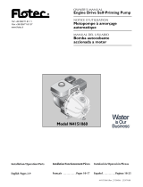
FIG. 2
0
1
2
3
4
5
6
7
8
9
10
10,6
3,6
0,3
2345678910 11 12
1,3
pression marche
pression arrêt
FIG. 1
HA MAX.
HC MINI.
OU
OR
OU
OR
100 mm
MINI
2%
a) b) 10/15 bars
1
2
9
12
14
13
3
8
4
5
7
11 11
15
1211
10
6
1
2
2
4

5
PEPE
PE
1
1 - Disjoncteur
Circuit breaker
2 - Pressostat
Pressure switch
3 - Moteur
Motor
23
PE 1
PE 3
FIG. 3
920
4 Ø17
590
FIG. 4

6
1. GÉNÉRALITÉS
La notice de montage et de mise en service fait partie intégrante du
matériel et doit être disponible en permanence à proximité. Le strict
respect de ses instructions est une condition nécessaire à l'installation
et à l'utilisation conformes du matériel.
La rédaction de la notice de montage et de mise en service corres-
pond à la version du matériel et aux normes de sécurité en vigueur
à la date de son impression.
1.1 Applications
Le surpresseur a pour fonction essentielle d'assurer la mise et le main-
tien sous pression d'un réseau de distribution d'eau à pression insuffi-
sante ou inexistante dans le domaine domestique ou industriel.
L'alimentation et la distribution en eau est possible à partir d'un puits,
d'une rivière ou d'une bâche.
La relève de pression d'un réseau d'eau de ville insuffisant est possible
à condition que la pression totale ne dépasse pas 10 bars.
1.2 Caractéristiques techniques
• Pression maxi de service : 10 bars
• Hauteur maxi. d'aspiration : 5 m
• Température de l’eau : + 50° C maxi
• Température ambiante : + 40° C maxi
• Tension mono : 230 - 240V
tri : 230 - 400V / 240 - 415V
• Masse : de 74 à 108 kg
• DN aspiration : 1”1/4
• DN refoulement : 1”
• Débit moyen : de 2000l/h à 5000 l/h*
• Capacité du réservoir : de 50 l à 200 l*
• Pression marche : de 4 à 4,5 bars*
• Pression arrêt : de 6 à 6,5 bars*
* Suivant modèles
2. SÉCURITÉ
Ce manuel renferme des instructions essentielles qui doivent être res-
pectées lors du montage et de l’utilisation.
C’est pourquoi il est indispensable que le monteur et l’opérateur du
matériel en prennent connaissance avant de procéder au montage
et à la mise en service.
Les instructions à respecter ne sont pas uniquement celles de sécuri-
té générale de ce chapitre, mais aussi celles de sécurité particulière
qui figurent dans les chapitres suivants, accompagnées d’un symbo-
le de danger
.
2.1 Symboles des consignes du manuel
Symbole général de danger.
Consignes relatives aux risques électriques.
Remarque : ...
Signaux
Situation extrêmement dangereuse.
Le non-respect entraîne la mort ou des blessures
graves.
L’utilisateur peut souffrir de blessures
(graves). « Avertissement » implique que
des dommages corporels (graves) sont vraisemblables lorsque
l’indication n’est pas respectée
Il existe un risque d’endommager la
pompe/installation. « Attention » Signale une ins-
truction dont la non-observation peut engendrer un dommage pour
le matériel et son fonctionnement.
Remarque : Remarque utile sur le maniement du produit. Elle fait
remarquer les difficultés éventuelles.
2.2 Qualification du personnel
Il convient de veiller à la qualification du personnel amené à réaliser
le montage.
2.3 Dangers encourus en cas de non-observation des consignes
La non-observation des consignes de sécurité peut constituer un
danger pour les personnes, la pompe ou l’installation. Elle peut éga-
lement entraîner la suspension de tout recours en garantie. Plus pré-
cisément, les dangers encourus peuvent être les suivants :
• défaillance de fonctions importantes de la pompe ou de
l'installation.
• défaillance du processus d’entretien et de réparation prescrit.
• dangers pour les personnes par influences électriques, méca-
niques ou bactériologiques.
• dommages matériels.
2.4 Consignes de sécurité pour l’utilisateur
Il convient d’observer les consignes en vue d’exclure tout risque
d’accident.
Il y a également lieu d’exclure tout danger lié à l’énergie électrique.
On se conformera aux dispositions de la réglementation locale ou
générale [IEC, VDE, etc.], ainsi qu’aux prescription de l’entreprise qui
fournit l’énergie électrique.
2.5 Conseils de sécurité pour les travaux d’inspection et de montage
L’utilisateur doit faire réaliser ces travaux par une personne spéciali-
sée qualifiée ayant pris connaissance du contenu de la notice.
Les travaux réalisés sur la pompe ou l’installation ne doivent avoir lieu
que si les appareillages correspondants sont à l’arrêt.
2.6 Modification du matériel et utilisation de pièces détachées non
agréées
Toute modification de la pompe ou de l'installation ne peut être
effectuée que moyennant l'autorisation préalable du fabricant.
L'utilisation de pièces de rechange d'origine et d'accessoires autori-
sés par le fabricant garantit la sécurité.
L'utilisation d'autres pièces dégage la société Salmson de toute res-
ponsabilité.
2.7 Modes d'utilisation non autorisés
La sécurité de fonctionnement de la pompe/l’installation livrée n’est
garantie que si les prescriptions précisées au chap. 4 de la notice
d’utilisation sont respectées. Les valeurs indiquées dans le catalogue
ou la fiche technique ne doivent en aucun cas être dépassées, tant
en maximum qu’en minimum.
3. TRANSPORT ET STOCKAGE
Dès réception du matériel, vérifier s’il n’a pas subi de dommages
durant son transport. En cas de défaut constaté, prendre dans les
délais prévus toutes dispositions nécessaires auprès du transporteur.
Manipuler la pompe avec précaution pour res-
pecter la géométrie et l’alignement de l’ensemble
hydraulique.
4. PRODUITS ET ACCESSOIRES
4.1 Descriptif technique (Voir FIG. 1)
1- Pompe MULTI-V.
2- Bouchon de remplissage et de purge.
3- Bouchon de vidange et d'amorçage.
4- Réservoir.
5- Manomètre.
6- Contacteur pressostatique.
7- Flexible de liaison pompe / réservoir.
8- Valve de gonflage.
9- Coffret de protection version triphasé
(disjoncteur magnéto-thermique.
HA - Hauteur d'aspiration maxi.
HC - Hauteur de charge mini.
DANGER !
AVERTISSEMENT !
ATTENTION !
FRANCAIS
ATTENTION !

7
HA et HC - Voir les caractéristiques de la pompe.
4.2 Accessoires (en option)
10 - Clapet de pied de crépine (Section de passage maxi 1mm).
11 - Vanne 1/4T à l’aspiration.
12 - Vanne 1/4T au refoulement.
13 - Clapet anti-retour.
14 - Support tuyauterie.
15 - Crépine.
La pompe Multi-V est reliée à un réservoir à vessie interchan-
geable en butyl qualité alimentaire, offrant toute garanti
d’hygiène à l’eau.
Protection
Hydromini monophasé : protection thermique moteur intégrée au
bobinage, réarmement automatique. Nous préconisons une protec-
tion magnétique (non fournie).
Hydromini triphasé : protection magnéto-thermique dans coffret de
protection, réarmementmanuel.
Protection manque d’eau : Nous recommandons sa protection par
un dispositif adapté (interrupteur à flotteur, pressostat).
4.3 Principe de fonctionnement
La pompe en marche envoie de l'eau dans la vessie qui comprime
l'air dans le réservoir. Dès que la pression réglée maxi. est obtenue, la
pompe s'arrête.
L'air, en appuyant sur la vessie, refoule l'eau dans la tuyauterie de dis-
tribution dès l'ouverture d'un robinet.
Lorsque l'on soutire de l'eau jusqu'à la pression mini, la pompe se met
en marche pour alimenter en eau et remplir à nouveau la vessie.
Le contacteur préssostatique (Fig. 1, rep.6) assure le fonctionnement
automatique du surpresseur, la lecture des pressions se fait sur le
manomètre.
La réserve d'eau contenue dans la vessie permet le soutirage d'eau
sans mise en route de la pompe.
5. INSTALLATION
5.1 Local
S'assurer que la porte du local autorise le libre accès au surpresseur.
Le surpresseur doit être installé dans un local facilement accessible,
normalement aéré et protégé du gel.
5.2 Montage (Voir FIG. 4)
Montage sur un sol bien lisse et horizontal.
Des plots anti-bruits et vibrations évitent toute transmission de bruit de
circulation d'eau. Il n'est donc pas nécessaire de prévoir de matériau
isolant au sol.
5.3 Raccordement hydraulique
Alimentation en eau
Par tube fileté à visser directement dans la contre-bride ovale tarau-
dée.
Le surpresseur peut être alimenté en eau en général à partir :
- d’un puits : la hauteur d’aspiration maxi de la pompe est de 5m.
- d’une bâche de stockage alimenté sur réseau eau de ville, à
niveau ou en charge.
En fonction de l'alimentation en eau, il est impératif de monter un cla-
pet de pied-crépine dans le cas de puits et rivière.
Le diamètre de la tuyauterie d'aspiration ne doit jamais être inférieur
à celui de la pompe. Limiter la longueur horizontale de la tuyauterie
d'aspiration et éviter toutes causes de pertes de charge (rétrécisse-
ment, coudes...).
Avec tuyauterie rigide, utiliser des supports ou colliers pour éviter que
le poids des tuyauteries ne soit supporté par la pompe (Fig. 1, rep.
14). Une flèche sur le corps de la pompe indique le sens de circula-
tion du fluide.
Distribution
DN ORIFICES
Type d'Hydromini Aspiration (taraudé) Refoulement (taraudé)
MULTi-V 200 1"1/4 - (33-42) 1" - (26-34)
MULTi-V 400 1"1/4 - (33-42) 1" - (26-34).
5.3 Raccordements électriques
Les raccordements électriques et les contrôles doivent être
effectués par un électricien agréé et conformément aux
normes en vigueur.
Réseau d'alimentation (Voir FIG. 3)
Monophasé : retirer le capot du contacteur manométrique et rac-
corder un câble électrique à 3 conducteurs (2 phases + terre) aux
bornes 2 et 4 (Fig. 2).
Triphasé : retirer le capot du coffret de protection et raccorder un
câble électrique à 4 conducteurs (3 phases + terre) aux bornes L1-L2-
L3.
Contrôler l'intensité réglée sur le disjoncteur en la comparant à la
plaque signalétique située sur la pompe. Au besoin, réajuster en tour-
nant la molette.
NE PAS OUBLIER DE RACCORDER LA MISE A LA TERRE (Conducteur Vert-
Jaune).
Une erreur de branchement électrique endommagerait le
moteur. Le câble électrique ne devra jamais être en contact
ni avec la tuyauterie ni avec la pompe, et être à l'abri de
toute humidité.
6. MISE EN ROUTE
Ne jamais faire fonctionner le module à sec, même un court
instant.
6.1 Remplissage - dégazage
Pompe en charge
- Fermer la vanne au refoulement (Fig 1, rep. 12).
- Dévisser le bouchon de remplissage (Fig. 1, rep. 2) et l'enlever.
- Dévisser de 4 à 5 tours le bouchon de vidange amorçage (Fig. 1,
rep. 3) pour mettre en relation le corps d'aspiration et le corps de
refoulement.
- Ouvrir progressivement la vanne à l'aspiration (Fig. 1, rep. 11) et pro-
céder au remplissage complet de la pompe par l'orifice de rem-
plissage.
- Ne revisser le bouchon de remplissage qu'après sortie d'eau et
complète évacuation de l'air.
Pompe en aspiration (Fig. 1)
- Fermer la vanne au refoulement (rep. 12).
- Ouvrir la vanne à l'aspiration (rep. 11).
- Dévisser le bouchon de remplissage (rep. 2) et l'enlever.
- Dévisser de 4 à 5 tours le bouchon de vidange amorçage, (rep. 3)
situé sur le corps de la pompe.
- A l'aide d'un entonnoir engagé dans l'orifice, remplir lentement et
complètement la pompe et la tuyauterie d’aspiration.
- Après sortie d'eau et évacuation totale de l'air, le remplissage est
terminé.
- Revisser les bouchons.
6.2 Gonflage du réservoir
Vérifier la pression de gonflage du réservoir, réajuster si nécessaire en
gonflant par la valve du réservoir (fig. 1, rep. 8).
La pression doit être de 0,3 bar inférieure à la pression de mise en
marche de la pompe.
6.3 Manomètre
Découper la tétine du manomètre (Fig. 1 - rep. 5) pour le mettre à
pression atmosphérique.
6.4 Réglages
Contrôle du sens de rotation (moteur tri uniquement).
- Mettre le moteur sous tension (une brève impulsion en enfonçant
FRANCAIS

8
FRANCAIS
le bouton marche sur le contacteur) et vérifier que celui-ci tourne
bien dans le sens indiqué par la flèche.
En cas d'inversion, croiser deux fils au bornier du contacteur presso-
statique.
Réglage du contacteur pressostatique
Le réglage ne peut être effectué que lorsque l'appareil est
sous pression.
6.4.1 Modèle mono et tri (Voir FIG. 1 et 2)
Principe : le réglage s'effectue en agissant sur l'écrou (Fig. 2, rep. 1)
pour obtenir le point haut (arrêt de la pompe) et sur l'écrou (Fig. 2,
rep. 2) pour régler le point bas (mise en route).
- Tourner dans le sens horaire l'écrou (Fig. 2, rep. 1), la valeur du point
haut augmente.
- Tourner dans le sens horaire l'écrou (Fig. 2, rep. 2), la valeur du point
bas diminue (l'écart augmente).
Avant de procéder aux réglages du contacteur pressostatique, choi-
sir les pressions de marche et d'arrêt. Nous vous conseillons :
marche : 4 b, arrêt : 6 b (maxi. 10 bars).
Si vous choisissez d'autres points, vérifier que l'intersection des pres-
sions marche et arrêt se trouve dans la zone de fonctionnement du
contacteur pressostatique (Fig. 2b).
Après avoir choisi les pressions de marche et d'arrêt, procéder de la
façon suivante :
Ouvrir la vanne au refoulement (repère 11)
pour faire chuter la pression.
Fermer la vanne au refoulement (repère 11).
Retirer le capot du contacteur.
Tourner à fond les écrous (repère 1 & 2)
dans le sens horaire sans les bloquer.
Mettre la pompe en marche pour faire monter la pression
(maxi. 4 ou 10 bars suivant la version).
Couper l'alimentation à la pression d'arrêt pompe désirée
(lecture au manomètre).
Tourner l'écrou (repère 1) dans le sens anti-horaire jusqu'au déclic
perceptible à l'oreille.
Ouvrir la vanne au refoulement (repère 12) pour faire chuter la
pression jusqu'au niveau de démarrage pompe souhaité
(lecture au manomètre) et la fermer.
Tourner l'écrou (repère 2) dans le sens anti-horaire.
Si un déclic se produit.
Mettre la pompe en marche et
contrôler vos réglages.
Réglages OK
Remettre le
capot
Mise en
service
Réglages non
précis
Voir § "princi-
pe" et affiner
les réglages
Réglages OK
Si pas de déclic.
Vérifier vos points de fonction-
nements et la pression de pré-
gonflage du réservoir (elle
doit être inférieure de 0,3 bars
à la pression de mise en
marche pompe).
Au besoin, choisir 2 nouveaux
points et ajuster la pression de
prégonflage.

9
Remplir la pompe avant toute nouvelle utilisation.
Ne pas laisser fonctionner la pompe, vanne de refoulement
fermée, au-delà de quelques minutes.
nous vous recommandons de vous adresser au SAV SALMSON, seuls
habilités pendant la période de garantie à procéder au démonta-
ge-remontage de nos matériels.
HOTLINE TECHNIQUE : 0 820 0000 44
INCIDENTS
8.1 LA POMPE
TOURNE MAIS NE
DÉBITE PAS.
8.2 LA POMPE VIBRE.
8.3 LA POMPE
CHAUFFE
ANORMALEMENT.
8.4 LA POMPE NE
DONNE PAS UNE
PRESSION
SUFFISANTE.
8.5 L’INSTALLATION
DISJONCTE.
8.6 LE DÉBIT EST
IRRÉGULIER.
CAUSES
a) Les organes internes sont obstrués
par des corps étrangers
b) Tuyauterie d'aspiration obstruée.
c) Entrée d'air par la tuyauterie
d'aspiration.
d) La pompe est désamorçée.
e) La pression à l'aspiration est trop
faible, elle est généralement accom-
pagnée de bruit de cavitation.
f) La pompe tourne à l'envers
(moteur triphasé).
g) Le moteur est alimenté à une tension
insuffisante.
a) Mal serrée sur son châssis.
b) Corps étrangers obstruant la pompe.
c) Rotation dure de la pompe.
a) Mauvais branchement électrique.
b) Tension insuffisante.
c) pompe obstruée par des corps
étrangers.
d) température ambiante supérieure
à + 40° C.
a) Le moteur ne tourne pas à sa vitesse
normale (corps étrangers, moteur
mal alimenté...)
b) Le moteur est défectueux.
c) Mauvais remplissage de la pompe.
d) Le moteur tourne à l'envers
(moteur triphasé)
a) Valeur trop faible du disjoncteur
(moteur triphasé)
b) La tension est trop faible.
c) Une phase est coupée.
d) Le disjoncteur est défectueux.
a) La hauteur d'aspiration (HA) n'est pas
respectée.
b) La tuyauterie d'aspiration est d'un
diamètre inférieur à celui de la
pompe.
c) La crépine et la tuyauterie
d'aspiration sont partiellement obs-
truées.
REMÈDES
a) Faire démonter la pompe et nettoyer.
b) Nettoyer toute la tuyauterie.
c) Contrôler l'étanchéité de toute la conduite jusqu'à la pompe et
étancher.
d) Réamorçer par remplissage pompe. Vérifier l'étanchéité du clapet de
pied.
e) Trop de pertes de charge à l'aspiration, ou la hauteur d'aspiration est trop
élevée (contrôler le NPSH de la pompe installée).
f) Croiser deux fils de phase au bornier du contacteur pressostatique pour
inverser le sens de rotation.
g) Contrôler la tension aux bornes du moteur et la bonne section des
conducteurs.
a) Vérifier et visser complètement les écrous des boulons ou des goujons.
b) Faire démonter la pompe et nettoyer.
c) Vérifier que la pompe tourne librement sans opposer de résistance
anormale.
a) Vérifier les connexions à la pompe.
b) Vérifier la tension aux bornes du moteur, cette tension doit se situer à +
ou - 10 % de la tension nominale.
c) Faire démonter la pompe et nettoyer.
d) Le moteur est prévu pour fonctionner à une température ambiante maxi
de + 40° C.
a) Faire démonter la pompe et remédier à l'anomalie.
b) Le remplacer.
c) Procéder au remplissage de la pompe et purger jusqu'à complète dispa-
rition des bulles d'air.
d) Croiser deux fils de phase au bornier du contacteur pressostatique pour
inverser le sens de rotation.
a) Contrôler l'intensité à l'aide d'un ampèremètre, ou afficher la valeur de
l'intensité inscrite sur la plaque moteur.
b) Vérifier la bonne section des conducteurs du câble électrique.
c) La vérifier et changer le câble électrique si nécessaire.
d) Le remplacer.
a) Revoir les conditions d'installation décrites dans ce manuel.
b) La tuyauterie d'aspiration doit être de même diamètre que l'orifice
d'aspiration pompe.
c) Démonter et nettoyer.
FRANCAIS
7. ENTRETIEN - MAINTENANCE
- En période de gel et d’arrêt prolongé de la pompe, il est nécessai-
re de vidanger la pompe, en dévissant le bouchon inférieur.
- Remplir la pompe avant toute nouvelle utilisation.
- Ne pas laisser fonctionner la pompe, vanne de refoulement fermée
au delà de quelques secondes.
8. INCIDENTS DE FONCTIONNEMENT
Avant toute intervention METTRE HORS TENSION le
module.
ATTENTION !

10
ENGLISH
1. GENERAL
These installation and operating instructions are integral part of the
product. They must be kept readily available at the place where the
product is installed. Strict adherence to these instructions is a pre-
condition for the proper use and correct operation of the product.
These installation and operating instructions conform to the relevant
version of the product and the underlying safety standards valid at
the time to going to press.
1.1 Applications
The essential role of the booster is to pressurize a water distribution
network in which the pressure is too low or non-existent, in domestic
and industrial applications.
Water supply and distribution is possible from a well, a stream or a
tank.
It is possible to boost an insufficient town water pressure provided that
the total pressure does not exceed 10 bars.
1.2 Technical characteristics
• Max. operating pressure : 10 bars
• Max. suction height : 5 m
• Water temperature : + 50° C maxi
• Max. ambient temperature : + 40° C maxi
• Voltage Single-phase : 230 - 240V
Three-phase : 230 - 400V / 240 - 415V
• - Weight : 74 to 108 kg
• DN suction : 1”1/4
• DN discharge : 1”
• Flow rate : 2000l/h to 5000l/h*
• Capacity of tank : 50 l to 200 l *
• Start pressure : 4 to 4,5 bars*
• Stop pressure : 6 to 6,5 bars*
* depend models
2. SAFETY
These instructions contain important information wich must be follo-
wed when installing and operating the pump.
It is therefore imperative that they be read by both the installer and
the operator before the pump is installed or operated.
Both the general safety instructions in this section and the more spe-
cific safety points in the following section should be observed
.
2.1 Symbols used in the instruction
General danger symbol.
Hazards from electrical causes.
Note : ...
Signal words
Imminently hazardous situation. Will result in death
or serious injury if not avoided
Risk of damage to the pump/installation.
“Caution” alerts to the user to potential product
damage due to non-compliance with the safety
instructions.
Note : Useful information on the handling of the product.
It alerts to user to potential difficulties.
2.2 Personnel qualification
The pernonnel installing the pump must have the appropriate qualifi-
cation for this work.
2.3 Risks inccured by failure to comply with the safety instructions
Failure to comply with the safety precautions could result in personal
injury or damage to the pump or installation. Failure to comply with
the safety precautions could also invalidate any claim for damages.
In particular, failure to comply with these safety instructions could give
rise, for example, to the followings risks:
• Failure of important pump or system functions.
• Failure of specified mainteneance and repair methods.
• Personal injury due to electrical, mechanical and bacteriological
causes.
• Damage to property.
2.4 Safety instructions for the operator
The relevant accident precaution regulations must be observed.
Potential dangers caused by electrical energy must be excluded.
Local or general regulations [e.g. IEC, VDE, etc.] and directives from
local energy supply companies are to be followed.
2.5 Safety instuctions for inspection and assembly
The operator must ensure that all inspection and assembly work is
carried out by authorised and qualified specialists who have careful-
ly studied these instructions.
Work on a pump or installation should only be carried out ounce the
latter has been brought to a standstill.
2.6 Unauthorised modification and manufacture of spares parts
Changes to the pump/machinery may only be made in agreement
with the manufacturer. The use of original spare parts and accesso-
ries authorised by the manufacturer will ensure safety. The use of any
other parts may invalidate claims invoking the liability of the manu-
facturer for any consequences.
2.7 Improper use
The operating safety of the pump or installation can only be guaran-
teed if it is used in accordance with paragraph 4 of the operating
instructions. All values must neither exceed nor fall below the limit
values given in the catalogue or data sheet.
3. TRANSPORT, HANDLING AND STORAGE
When receiving the material, check that there has been no damage
during the transport. If any defect has been stated, take all necessa-
ry steps with the carrier within the allowed time.
Handle the pump carefully so as not to alter the
goemetry and the alignment of the unit.
4. PRODUCTS AND ACCESSORIES
4.1 Description (see FIG. 1)
1- Multi-V pump
2- Venting and filling plug
3- Draim-priming plug
4- Bladder tank
5- Pressure gauge
6- Pressure switch
7- Pump/bladder tank connecting hose
8- Pressurization valve
9- Three-phase protection box (magneto-thermal circuit breaker)
HA - Maximum suction height
HC - Minimum pressure head
HA and HC - see characteristics of pump
4.2 Acessories (optionnal)
10 - Foot-valve strainer (max opening 1mm)
11 - Quarter-turn suction valve
12 - Quarter turn discharge valve
13 - Non-return valve
14 - Piping support.
15 - Strainer
DANGER !
WARNING !
CAUTION !
CAUTION !

11
ENGLISH
The multi-V pump is connected to an interchangeable blad-
der tank made of food-grade butyl rubber for complete assu-
rance of healthy water.
Protection
Single-phase Hydromini : thermal protection of motor incorporated
in winding; automatic reset. We recommend magneto protection
(not delivered)
Three-phase Hydromini : magneto-thermal incorporated in the pro-
tection box, manual reset.
Dry run protection : we recommend its protection by an adapted
device (float switch, pressure switch).
4.3 Operating principle
The pump in operation discharges water into the bladder, compres-
sing the air in the tank. When the max. pressure set is reached , the
pump stops.
The air presses on the bladder, driving water in the distribution pipe
when a tap is opened.
When enough water is drawn of for the minimum pressure to be rea-
ched, the pump starts to deliver water and refill the bladder.
The pressure switch (Fig. 1, item 6) automates the operation of the
booster; the pressures can be read on the pressure gauge.
The reserve of water in the bladder means that water can be drawn
without starting the pump.
5. INSTALLATION
5.1 Room
Ensure the premise doors allows free access to the booster pump. The
booster should be installed in a room that easy to reach, normally
ventiled and protected from frost.
5.2 Mounting (see FIG. 4)
Montage sur un sol bien lisse et horizontal.
Des plots anti-bruits et vibrations évitent toute transmission de bruit de
circulation d'eau. Il n'est donc pas nécessaire de prévoir de matériau
isolant au sol.
5.3 Hydraulic connections
Water supply
By threaded tubes screwed directely into the tapped oval counter-
flanges.
The booster can be supplied with water, from:
- a well : the max. suction height of the pump is 5m.
- a storage tank supplied from a town network, at level or under pres-
sure.
Depending on the water supply, it is essential to fit : a foot valve-strai-
ner in the case of a well or stream.
The diameter of the suction piping must never be less than that of the
pump. Limit the horizontal length of the suction piping and avoid all
causes of losses of head (necking, bends, etc.).
With rigid piping, use supports or collars to avoid having the pump
bear the weight of the piping (fig. 1, item 14). An arrow on the pump
body indicates the pump direction of flow of the fluid.
Distribution
ND of ports (tapped)
Hydromini Suction Discharge
MULTi-V 200 1"1/4 - (33-42) 1" - (26-34)
MULTi-V 400 1"1/4 - (33-42) 1" - (26-34).
5.3 Electrical connections
The electrical connections and checks must be done by a
qualified electrician in accordance with the standards in
force.
Power supply network (see Fig.3)
Single-phase : rremove the cover of the pressure and connect a 3-
connectors cable (2 phases + earth) to terminals 2 and 4 (Fig. 2).
Three-phase : remove the cover of the pressure and connect a 4-
connectors cable (3 phases + earth) to terminals L1,L2,L3.
Check the current set on the thermal relay, and compare it to what
is marked on the data plate on the pump. If necessary, readjust by
turning the thumbwheel.
Contrôler l'intensité réglée sur le disjoncteur en la comparant à la
plaque signalétique située sur la pompe. Au besoin, réajuster en tour-
nant la molette.
DO NOT FORGET TO CONNECT THE EARTHING LEAD (Green and yellow
conductor).
An electrical connection error would damage the motor.
The cord must never the piping or the the pump, and must be
kept away from all moisture.
6. STARTING-UP
Never run the module dry more than a few seconds.
6.1 Filling , degassing
Pump under pressure
- Close the discharge valve (Fig. 1, item 12).
- Unscrew and remove the pilling plug (Fig. 1, item 2).
- Unscrew the drain-priming plug (Fig. 1, item 3) 4 or 5 turns to inter-
connect the suction and discharge casings.
- Gradually open the discharge valve (Fig. 1, item 11) and proceed
to fill the pump completely via the filling port.
- Screw the filling plug back in only after water has flowed out and all
air has been eliminated.
Pump in suction (Fig. 1)
- Close the discharge valve (item 12).
- Open the suction valve (item 11).
- Unscrew and remove the filling plug (item 2).
- Unscrew the drain-priming plug (item 3) on the pump body 4 or 5
turns.
- Using a funnel inserted in the port, fill the pump and the suction
piping, slowly and completely.
- After water flows out and all air has been eliminated, filling is com-
plete.
- Screw the plugs back in.
6.2 Pressurization of tank
Check the tank pressure of tank and correct if necessary by pressuri-
zing via the tank valve (Fig.1, item 8).
The pressure must be 0.3 bar less than the pump starting pressure.
6.3 Pressure gauge
Cut the nipple of the pressure gauge (Fig. 1, item 5) to vent it.
6.4 Adjustments
Check of direction of rotation (three-phase motor only.
- Power up the motor and check that in fact it turns in the direction
indicared by the arrow placed on the pump housing.
If it turns the wrong way, interchange two wires on the motor termi-
nal block.
Adjustement of pressure contactor
The adjustment can only be made with the equipment pres-
surized.
6.4.1 Single-phase and three-phase models (see Fig. 1 and 2)
Principe : the adjustment is made by turning the nut (Fig. 2, item 1) to
adjust the high point (stopping of pump) and the nut (Fig. 2, item 2)
to adjust the low point (starting).
- Turn the nut (Fig. 2, item 1) clockwise; the value of the high point

12
Open the discharge valve (item 11)
to depressurize.
Close the discharge valve (item 11).
Remove the cover from the contactor.
Turn the nuts (items 1 & 2) fully clockwise
without tightening.
Start the pump to raise the pressure (max. 4 or 10 bars
depending on version).
Cut off power at the desired pump stopping pressure
(read on pressure gauge).
Turn the nut (item 1) anticlockwise until a
click can be heard.
Open the discharge valve (item 12) to lower the pressure
to the desired pump starting level
(read on pressure gauge), then close it.
Turn the nut (item 2) anticlockwise.
If a click is heard.
Start the pump and check your
adjustments.
Adjustments OK
Put the cover
back on
Commission
Adjustments
imprecise
See "principle"
and
refine
the adjustments
Adjustments OK
If no click.
Check your operating points
and the tank
pre-pressurization
pressure
(it must be 0.3 bars less than
the pump starting pressure).
If necessary, choose 2 new
points and adjust the pre-
pressurization pressure.
ENGLISH
increases.
- Turn the nut (Fig. 2, item 2) clockwise; the value of the low point
increases (the difference increases).
Before adjusting the pressure contactor, choose the starting and the
stopping pressures. We recommend:
Starting: 4 bars, stopping : 6 bars (maxi. 10 bars)
If you choose other points, check that the intersection of the starting
and stopping pressures is in the contactor’s operating range (Fig. 2b).
After choosing the starting and stopping pressures, proceed as follow:

13
ENGLISH
Fill the pump before using again.
Do not let the pump run more than a few seconds with the
discharge valve closed.
PROBLEMS
8.1 THE PUMP RUNS
BUT THERE IS NO
FLOW.
8.2 THE PUMP
VIBRATES.
8.3 THE PUMP
OVERHEATS.
8.4 THE PUMP FAILS TO
DELIVER
SUFFICIENT
PRESSURE.
8.5 THE INSTALLATION
TRIPS OUT.
8.6 THE FLOW IS
IRREGULAR.
CAUSES
a) The internal units are obstructed by
foreign bodies.
b) Suction piping obstructed.
c) Intake of air via suction piping.
d) The pump is out of water.
e) The suction pressure is too low ; this is
generally accompanied by cavita-
tion noise.
f) The pump turns the wrong way (tree-
phase motor).
g) The motor is supplied at too low a vol-
tage.
a) Poorly secured on its frame.
b) Foreign bodies obstructing the pump.
c) Pump hard to turn.
a) Poor electrical connection.
b) Voltage too low.
c) Pump obstrycted by foreign bodies.
d) Ambient temperature above +40°C.
a) The motor is not turning at its normal
speed (foreign bodies, defective
motor, power supply, etc.).
b) The motor is defective.
c) Poor filling of pump.
d) The motors turns the wrong way
(three-phase motor)
a) The rating of the thermal relay is too
low (three-phase motor)
b) The voltage is too low.
c) One phase is open-circuit.
d) The thermal relay of the circuit brea-
ker is faulty.
a) The suction height (HA) is too great.
b) The suction piping is of a smaller dia-
meter than the pump.
c) The strainer and suction piping are
partially obstructed.
REMEDIES
a) Have the pump removed and cleaned.
b) Clean all the piping.
c) Check the tightness of the whole pipe up to the pump and seal it.
d) Reprime by filling the pump. Check the tightness of the foot valve.
e) Excessive losses of head in suction, or suction height too great (check the
NPSH of the pump installed).
f) Interchange two phases wires on the pressure switch terminal block to
reverse the direction of rotation.
g) Check the voltage on the motor terminals and the sections of the
conductors.
a) Check and completely tighten the nuts of bolts and studs.
b) Have the pump removed and cleaned.
c) Check that the pump turns freely without opposing abnormal resistance.
a) Check the connections to the pump.
b) Check the voltage on the terminals of the motor ; it must be within + or –
10% of the nominal voltage.
c) Have the pump removed and cleaned.
d) The motor is designed to operate at an ambient temperature of up to +
40°C.
a) Have the pump removed the anomaly corrected.
b) Remplace it.
c) Fill the pump and bleed until all air bubbles disappear.
d) Reverse the direction of rotation by interchanching two phases wires on
the pressure switch terminal block.
a) Check the current using an ammeter, or set tothe current marked on the
motor data plate.
b) Check the section of the conductors of the power cord.
c) Check it or/and replace it.
d) Replace it.
a) Review the installation conditions described in this manual.
b) The suction piping must be of the same diameter as the pump suction
port.
c) Remove and clean.
7. MAINTENANCE
- In frosty weather and for prolonged stoppages of the pump, it must
be drained by unscrewing the buttom plug.
- Fill the pump before using again.
- Do not let the pump run more than a few seconds with the dischar-
ge valve closed.
8. PROBLEMS, CAUSES AND REMEDIES
Before any action, POWER DOWN the module.
ATTENTION !

14
NOTES

15
NOTES

CB.N° 4.017.731/Ed.3
CE MANUEL DOIT ETRE REMIS A
L'UTILISATEUR FINAL ET ETRE TOUJOURS
DISPONIBLE SUR SITE.
FRANCAIS
THIS LEAFLET HAS TO BE GIVEN TO THE
END USER AND MUST BE LEFT ON SITE.
FRANCAIS
SERVICE CONSOMMATEUR
Tél. 0820 0000 44
Espace Louis Lumière - Bâtiment 6
53, boulevard de la République - 78403 Chatou Cedex
www.salmson.com
POMPES SALMSON - SAS AU CAPITAL DE 16.775.000 €SIREN 313 986 838 RCS VERSAILLES - APE 291C
PORTUGAL
Rua Alvarez Cabral, 250/255
4050 - 040 Porto
PORTUGAL
TEL. : (351) 22 208 0350
TEL. : (351) 22 207 6910
FAX : (351) 22 200 1469
mail@salmson.pt
SALMSON SOUTH AFRICA
Unit 1, 9 Entreprise Close,
Linbro Business Park - PO Box 52
EDENVALE, 1610
Republic of SOUTH AFRICA
TEL. : (27) 11 608 27 80/ 1/2/3
FAX : (27) 11 608 27 84
SALMSON ITALIA
Via J. PeriI 80 I
41100 MODENA
ITALIA
TEL. : (39) 059 280 380
FAX : (39) 059 280 200
info.tecniche@salmson.it
W.S.L. LEBANON
Bou Khater building - Mazda Center
Jal El Dib Highway - PO Box 90-281
Djeideh El Metn 1202 2030 - Beiruth
LEBANON
TEL. : (961) 4 722 280
FAX : (961) 4 722 285
SALMSON ARGENTINA S.A.
Av. Montes de Oca 1771/75
C1270AABE
Ciudad Autonoma de Buenos Aires
ARGENTINA
TEL.: (54) 11 4301 5955
FAX : (54) 11 4303 4944
info@salmson.com.ar
SALMSON VIETNAM
E-TOWN - Unit 3-1C
364 CONG HOA - TAN BINH Dist.
Hochi minh-ville
VIETNAM
TEL. : (84-8) 810 99 75
FAX : (84-8) 810 99 76
/