Page is loading ...

Model 3550 Programmable LCR Meter Instruction Manual a
TEGAM Inc.
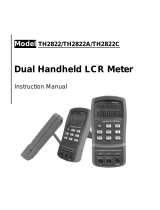
Model 3550
42.0Hz-5.00MHz
Fully Programmable
LCR Meter
MODEL 3550
Instruction Manual
PN# 3550-900-01CD
Publication Date April 2004
REV. B
© Copyright 2004, TEGAM, Inc. All rights reserved.
NOTE: This user’s manual was as current as possible when this product was manufactured. However, products are
constantly being updated and improved. Because of this, some differences may occur between the descriptions in this
manual and the product received. Please refer to www.tegam.com for future updates of this manual.

Model 3550 Programmable LCR Meter Instruction Manual b

Model 3550 Programmable LCR Meter Instruction Manual c
Table of Contents
I INSTRUMENT DESCRIPTION............................................................................1-1
Instrument Description ........................................................................... 1-1
Feature Overview ................................................................................... 1-1
3550 Options and Accessories .................................................................. 1-4
Performance Specifications ...................................................................... 1-5
Table 1.1 – Model 3550 Measurement Range Limits ............................... 1-5
Table 1.2 – Model 3550 Measurement Frequencies................................. 1-7
Table 1.3 – Model 3550 Measurement Amplitudes .................................. 1-7
Table 1.4 – Model 3550 Amplitude Accuracies ....................................... 1-8
Table 1.5 – Model 3550 Measurement Ranges ....................................... 1-8
Table 1.6 – Typical Analog Measurement Times ..................................... 1-9
Table 1.7a – Absolute Comparator Operation......................................... 1-11
Table 1.7b – Percentage Comparator Operation ..................................... 1-11
Table 1.8 – Numeric Displays and Annunciators ..................................... 1-11
Formulas and Measurement Accuracy........................................................ 1-13
Table 1.9 – Series and Parallel Equivalent Circuit Measurements .............. 1-14
II PREPARATION FOR USE ..................................................................................2-1
Unpacking and Inspection........................................................................ 2-2
Safety Information and Precautions .......................................................... 2-2
Servicing Safety Summary ...................................................................... 2-4
Line Voltage and Fuse Selection ............................................................... 2-5
III QUICK START INSTRUCTIONS .........................................................................3-1
Power the Unit ....................................................................................... 3-2
Instrument Settings................................................................................ 3-2
Table 3.1 – Factory Default Settings .................................................... 3-2
Table 3.2 – Control Command Summary............................................... 3-3
Table 3.3 – Shift Function Summary .................................................... 3-4
Instrument Setup for Basic Measurements ................................................. 3-5
Table 3.4 – Settings Summary ............................................................ 3-5
Setting the Absolute Comparator.............................................................. 3-6
Setting the Percent Comparator ............................................................... 3-7
IV OPERATING INSTRUCTIONS............................................................................4-1
Basic Operation...................................................................................... 4-2
Default Parameters................................................................................. 4-2
Precautions ........................................................................................... 4-2
Measurement Tips .................................................................................. 4-2
Making Measurements that are Sensitive to Voltage and Current.............. 4-2
Measuring Earth Grounded Test Pieces ................................................. 4-2
Measurement Circuit Modes ................................................................ 4-3
Table 4.1 – Relationship Between Series and Parallel Equivalent Circuits ... 4-3
Negative Capacitance or Inductance Readings ....................................... 4-4
Zero Correction of Parasitic Impedance ................................................ 4-4
Table 4.2 – Short and Open Null Connections ........................................ 4-4

Model 3550 Programmable LCR Meter Instruction Manual d
Table of Contents
IV OPERATING INSTRUCTIONS CONT’D...............................................................
Measurement Tips ..................................................................................
Test Lead Requirements ..................................................................... 4-5
Figure 4.1a – Four-Wire Kelvin Measurement ........................................ 4-5
Figure 4.1b – Proper Application of Four Wire Kelvin Measurement ........... 4-5
Measurement Signal Levels................................................................. 4-6
Series or Parallel Circuit Modes............................................................ 4-6
Auto range Switching Threshold .......................................................... 4-6
Display Resolution ............................................................................. 4-6
AC Resistance of Coils with Cores ........................................................ 4-6
Front Panel Description ........................................................................... 4-7
Figure 4.2 – Front Panel Layout........................................................... 4-7
Power Switch.................................................................................... 4-8
Circuit Mode Panel............................................................................. 4-8
Trigger Panel .................................................................................... 4-8
Zero Panel ....................................................................................... 4-9
Range Selection Panel........................................................................ 4-9
Shift Key.......................................................................................... 4-10
Frequency Set Mode........................................................................ 4-10
Test Voltage Set Mode..................................................................... 4-11
Test Current Set Mode..................................................................... 4-11
Averaging Set Mode ........................................................................ 4-12
Key Lock Mode ............................................................................... 4-12
Comparator buzzer Function............................................................. 4-13
Trigger Delay Time.......................................................................... 4-13
Comparator Functions Mode ............................................................. 4-14
Defining Spot Frequencies for Zero Adjustments ................................. 4-14
RS-232C Settings Mode ................................................................... 4-15
Correction Frequency Limit Setting Mode............................................ 4-16
Spot Correction Mode (Open Correction) ............................................ 4-16
Spot Correction Mode (Short Correction) ............................................ 4-16
Unknown Terminals Panel................................................................... 4-17
Table 4.3 – Unknown Terminals........................................................... 4-17
Comparator Limit Set Panel ................................................................ 4-17
The Guard Terminal ........................................................................... 4-17
Remote Interface Status LEDs............................................................. 4-18
Panel Selector Switch......................................................................... 4-18
Panel Display LED.............................................................................. 4-18
Display A Parameter Selection Key....................................................... 4-18
Display A ......................................................................................... 4-18
Bin Display LED................................................................................. 4-18
Comparator State Annunciators........................................................... 4-19
Sample LED (Trigger Status)............................................................... 4-19
Comparator ON/OFF Switch ................................................................ 4-19
Display B Parameter Selection Key....................................................... 4-19
Display B ......................................................................................... 4-19

Model 3550 Programmable LCR Meter Instruction Manual e
Table of Contents
IV OPERATING INSTRUCTIONS CONT’D...............................................................
Front Panel Description Cont’d ............................................................
Display C Measurement Panel ............................................................. 4-20
Table 4.4 – CV/CC Indicators .............................................................. 4-21
Display C ......................................................................................... 4-21
Enter Key......................................................................................... 4-21
Rear Panel Description ............................................................................ 4-22
Figure 4.3 – Rear Panel Layout............................................................ 4-22
Making Accurate Measurements ............................................................... 4-23
Connections to the Device Under Test .................................................. 4-23
3-Terminal Measurement.................................................................... 4-23
4 or 5-Terminal Measurements............................................................ 4-23
Test Fixture Selection ........................................................................ 4-24
Table 4.4 – Impedance and Frequency Limitations of Kelvin Klip Leads ..... 4-24
Table 4.5 – Impedance and Frequency Limitations of the SMD Test Fixture 4-25
Zero Corrections ............................................................................... 4-26
Table 4.6 – Zero Correction Limits ....................................................... 4-26
Figure 4.4 – Terminal Connections for Zero Correction............................ 4-27
Equivalent Circuits............................................................................. 4-28
Table 4.7 – Equivalent Circuit Relationships .......................................... 4-29
Operating the 3550 ................................................................................ 4-30
Preparation ...................................................................................... 4-30
How to Perform a Zero Correction........................................................ 4-30
Measuring L, C, and R ........................................................................ 4-31
Measuring |Z| and |Y|........................................................................ 4-33
Measuring D, Q, Rs, Rp, G, X, B, and LJ................................................. 4-34
The Comparator..................................................................................... 4-35
Important Notes for the Absolute and Comparator Functions ................... 4-35
Absolute Value Settings...................................................................... 4-36
Percent Value Settings ....................................................................... 4-37
Bin Operation ................................................................................... 4-39
Figure 4.5 – Sequenced Bin Sorting ..................................................... 4-39
Figure 4.6 – Nested Bin Sorting........................................................... 4-40
Outputting the Comparator’s Results.................................................... 4-41
Audible Buzzer Operation ................................................................... 4-41

Model 3550 Programmable LCR Meter Instruction Manual
f
Table of Contents
V PROGRAMMING AND INTERFACING ................................................................5-1
Interfacing to the 3550 ........................................................................... 5-2
Control I/O Connector............................................................................. 5-2
Inputs ............................................................................................. 5-2
Figure 5.1 – Input Schematic .............................................................. 5-2
Outputs ........................................................................................... 5-3
Figure 5.2 – Output Schematic ............................................................ 5-3
Timing Diagrams............................................................................... 5-4
Figure 5.3a – Test Busy Operation ....................................................... 5-4
Figure 5.3b – Measure End Operation................................................... 5-4
Figure 5.3c – GO/NO-GO Operation ..................................................... 5-4
Table 5.1 – Connector Pin Designations ................................................ 5-5
Table 5.2 – Control I/O Function Summary ........................................... 5-6
Sample Diagram of External Connections to Sequencer........................... 5-7
RS-232C ............................................................................................... 5-8
Interface Cable ................................................................................. 5-8
Input Format .................................................................................... 5-8
Table 5.3a – Command Summary........................................................ 5-11
Table 5.3b – Command Summary cont’d .............................................. 5-12
Table 5.3c – Command Summary cont’d............................................... 5-13
Table 5.4 - Comparator Instructions..................................................... 5-14
Data Output Format for Measurement Settings ...................................... 5-15
Table 5.5a – Data Output Code Functions ............................................. 5-16
Table 5.5b – Data Output Code Functions cont’d .................................... 5-17
Monitor Output Format....................................................................... 5-18
Table 5.6c – Monitor Output Code Functions.......................................... 5-21
Table 5.6b – Monitor Output Code Functions cont’d ................................ 5-22
RS-232C Hardware and Computer Settings ........................................... 5-23
Sample Programs for RS-232C ............................................................ 5-23
The GPIB Interface (Optional) .................................................................. 5-28
General Description of GPIB................................................................ 5-28
Primary Specifications of GPIB ............................................................ 5-28
Table 5.7 – GPIB Functions................................................................. 5-28
Installation of the GPIB Board ............................................................. 5-29
Figure 5.4a – Rear View ..................................................................... 5-29
Figure 5.4b – Side View ..................................................................... 5-30
Figure 5.4c – Top View....................................................................... 5-30
Front Panel Status LEDs ..................................................................... 5-31
Local Key Switch ............................................................................... 5-31
GPIB Switches .................................................................................. 5-31
Delimiter Output Formats ................................................................... 5-31
Output Status Bits for Service Requests................................................ 5-31
Figure 5.5 – GPIB Status Bits.............................................................. 5-31
Additional Notes for Using the GPIB Interface ........................................ 5-31
Programming Examples...................................................................... 5-33

Model 3550 Programmable LCR Meter Instruction Manual g
Table of Contents
VI SERVICE INFORMATION ..................................................................................6-1
Warranty .............................................................................................. 6-2
Warranty Limitations .............................................................................. 5-2
Statement of Calibration ......................................................................... 6-2
Contact Information ............................................................................... 6-2
Repair Parts .......................................................................................... 6-3
Troubleshooting .................................................................................... 6-4
Preparation for Repair or calibration Service............................................... 6-5
Expedite Repair and calibration Form ........................................................ 6-6
Performance Verification Procedure........................................................... 6-7
Model 3550 Calibration Adjustment Procedure ............................................ 6-12
VII APPENDIX .......................................................................................................A.1
Setting the Constant Voltage Mode ........................................................... A.3
To Enable the Constant Voltage Mode................................................... A.3
Calculating the maximum Allowable Constant Voltage Setting.................. A.3
Setting the Constant Current Mode ........................................................... A.4
Calculating the maximum Allowable Constant Current Setting.................. A.4
Basic Measurement Accuracy Tables ......................................................... A.5
Table A.1 – Basic Accuracy Table......................................................... A.5
Table A.2 – Basic Accuracy Table [0.01V to 0.04V]................................. A.6
Table A.3 – Basic Accuracy Table [0.05V to 0.10V]................................. A.7
Table A.4 – Basic Accuracy Table [0.11V to 0.20V]................................. A.8
Table A.5 – Basic Accuracy Table [0.21V to 0.45V]................................. A.9
Table A.6 – Basic Accuracy Table [0.46V to 1.00V]................................. A.10
Table A.7 – Basic Accuracy Table [1.01V to 5.00V]................................. A.11
LC Impedance Calculation Chart ............................................................... A.12
Error Codes ........................................................................................... A.13

Model 3550 Programmable LCR Meter Instruction Manual h

Instrument Description
INSTRUMENT DESCRIPTION
PREPARATION FOR USE
QUICK START INSTRUCTIONS
OPERATING INSTRUCTIONS
PROGRAMMING & INTERFACING
SERVICE INFORMATION
APPENDIX

Model 3550 LCR Meter Instruction Manual Instrument Description
1-2
Instrument Description
The Model, 3550, is a high-speed LCR Meter capable of measuring Inductance (L), Capacitance(C),
Resistance (R), Absolute Impedance (|Z|), Absolute Admittance (|Y|), Dissipation factor (D),
Quality (Q), Serial Equivalent Resistance (Rs), Parallel Equivalent Resistance (Rp), Conductance
(G), Reactance (X), Susceptance (B), and Phase Angle (LJ). It has a wide measurement range, and
includes full adjustability of Measurement Frequency and Measurement Signal Level. It also
features Automatic adjustment for Zero Correction, Range Switching, and Series and Parallel Mode
Switching.
The basic comparator function of the 3550 is extended to allow sorting of components to up to 10
different bins. Up to 9 panels worth of measurement settings can be stored in the instrument’s
non-volatile memory for convenient recall. The instrument can perform a complete measurement
including a comparator judgment in as little as 40ms.
The 3550 has standard RS-232C and Control I/O Connector Interfaces with the availability of an
optional GPIB Interface. The Control I/Os are optically isolated thus making the instrument ideal
for noise immunity.
Feature Overview
The 3550 Programmable LCR Meter offers a complete solution for a wide variety of specialized LCR
measurement applications. Listed below are some of the features.
High Speed
The measurement time, including data display, zero correction, and comparator function is
approximately 40 milliseconds.
Extended Frequency Range
The Measurement Frequency can be adjusted between 42.0Hz - 5.00MHz.
Programmable Test Voltage and Current
The test signal level can be adjusted between 10mV to 5.00V in the constant voltage mode
and from 10µA to 99.99mA in the constant current mode.
Voltage & Current Monitor
The voltage at the test piece terminals and the current, which is flowing through the test
piece, can be displayed up to 3 significant digits.

Model 3550 LCR Meter Instruction Manual Instrument Description
1-3
Feature Overview cont’d:
4
1
/
2
Digits Resolution
"DISPLAY A" (L, C, R, |Z|, |Y|), and "DISPLAY B" (D, Q, R
S
, R
P
, G, X, B, LJ) can both display
up to 4
1
/
2
digits.
GO/NO-GO COMPARATOR
For L, C, R, |Z|, |Y|, D, Q, R
S
, R
P
, G, X, B, and LJ, upper and lower limit values can be set
for 9 items (10 categories), for up to 9 panels of settings.
Series or Parallel Equivalent Circuit Mode
When in "Auto" mode, Parallel or Series Equivalent Circuit measurements are automatically
determined by the active measurement range. In manual range, the Parallel or Series
Equivalent Circuit mode are user selectable.
Front Panel Key Lock
The Key Switch on the front panel can be set to lock the instrument settings for protection
against accidental changes.
Automatic Zero Correction of Parasitic Impedance
Performing Open and Short Circuit Zeroing cancel the offset errors caused by Stray
Capacitance, Stray Conductance, Residual Inductance, and Residual Resistance.
Non-Volatile Memory
All measurement settings such as the Zero Correction Values, Comparator Limits, Panel
Settings etc. are stored in non-volatile memory and are retained in the event of power loss.
Remote Operation
The TEGAM Model 3550 provides standard RS-232C and I/O Control Connector interfaces
for remote operation. There is an optional GPIB (IEEE-488) interface available for purchase.

Model 3550 LCR Meter Instruction Manual Instrument Description
1-4
3550 Options and Accessories
2005B - Chip Tweezers (5ft)
This four-terminal tweezer set makes
solid connections to chip components
in manual sorting applications.
Capacity of jaws is 12.7mm (0.5
in.). The 2005B Chip Component
Tweezer Set includes a 1.5m (5 ft)
cable for connection to the
2150/2160. Contact tips are
replaceable. P/N 47422.
47422 Chip Tweezer
Replacement Kit
Tweezer tips are intended to last
100,000 to 500,000 operations. An
optional tip replacement kit includes
12 replacement tips, 2 screws and 1
wrench.
3511 - SMD Test Fixture
Available for performing three
terminal measurements on surface
mount devices. Connects directly to
the front panel of the 3550. Use the
3511 for medium and high
impedance measurements.
3510-Radial Lead Adapter
This sorting fixture allows for efficient
four-wire measurement of leaded parts.
The test fixture features spring action
contacts for easy insertion and removal
of test components.
47454 – Kelvin Klips
Kelvin Klips allow solid four-terminal,
Kelvin connections to leaded
components. The jaws are assembled
with hardened gold-plated, beryllium
copper, which ensures low contact
resistance, low thermal emf to copper,
high corrosion resistance, and long
service life. An alligator clip is provided
allowing connection of a passive guard.
The assembly includes a 5 ft (1.5m)
cable for connection to the 3525.
NOTE: Under certain measurement
conditions, Kelvin Klips can cause a loss
of measurement accuracy. Fixtures
3510, 3511, or 2005B chip tweezers are
recommended for the following
component values:
C<100pF; L < 100µH; R > 1Mƻ
KK100- Kelvin Klip™ Rebuild
Kit
Kelvin Klip™ replacements for
construction or repair of Kelvin Klip
leads.
GPIB (IEEE-488) Cables
1583-3 – 1-meter GPIB buss cable
1583-6 – 2-meter GPIB buss cable
1583-9 – 3-meter GPIB buss cable
3505 – GPIB Interface
3550-900-01 – User’s Manual-
Hard Copy

Model 3550 LCR Meter Instruction Manual Instrument Description
1-5
Performance Specifications
The advertised specifications of the model 3550 are valid under the following conditions:
1. The instrument must be verified and/or adjusted using the methods and intervals as
described in the calibration section of this user’s manual.
2. The instrument must be in an environment, which does not exceed the limitations as
defined under “Environmental” in the Miscellaneous Specifications section.
3. The unit is allowed to warm up for a period of at least 30 minutes before measurements
are taken. A warm-up period of 60 minutes is recommended after exposure to or storage in
a high humidity, (non-condensing), environment.
4. Only TEGAM-manufactured Kelvin Klips™, Tweezers and other test fixtures are used with
this device during measurements.
Measurement Parameters:
Inductance (L), Capacitance(C), Resistance(R), Impedance (|Z|), Admittance (|Y|),
Dissipation Factor (D), Quality (Q), Equivalent Series Resistance (R
S
), Equivalent Parallel
Resistance (R
P
), Conductance (G), Reactance (X), Susceptance (B), and Phase Angle (LJ).
Measurement Ranges
Table 1.1 – Model 3550 Measurement Range Limits
Parameter Low Limit High Limit
L 320.0nH (At: 10ƻ 5MHz) 0.7500MH(At: 199.99Mƻ 42Hz) (LJ=90°)
C 0.160pF (At: 100kƻ 5MHz) 0.037F(At: 100mƻ 42Hz) (LJ=-90°)
R 0.01mƻ 199.99Mƻ
|Z| 0.01mƻ 199.99Mƻ
|Y| 5.000nS(199.99Mƻ) 100.00S(100mƻ)
D 0.0001 9.999
Q 0.1 1999.9
R
S
0.01mƻ 199.99Mƻ
R
P
0.01mƻ 199.99Mƻ
G 5.000nS(199.99Mƻ) 100.00S(100mƻ)
X 0.01mƻ 199.99Mƻ
B 5.000nS(199.99Mƻ) 100.00S(100mƻ)
LJ -180.00° 180.00°
NOTE: The Measurement Range is dependent on the Measurement Frequency. The figures in
parentheses are DUT impedance values.

Model 3550 LCR Meter Instruction Manual Instrument Description
1-6
Performance Specifications cont’d:
Basic Accuracy
0.1%
Display Specifications:
x Numeric Display (DISPLAY A)
L, C, R, |Z|, |Y| (4
1
/
2
digits)
x Numeric Display (DISPLAY B)
D, Q, R
S
, R
P
, G, X, B, LJ (4
1
/
2
digits)
x Numeric Display (DISPLAY C)
Frequency, Voltage, Current, Terminal Voltage, Terminal Current, PANEL (3 digits)
x Unit Prefix Display (DISPLAY A)
p, n, µ, m, k, M
x Unit Prefix Display (DISPLAY B)
n, µ, m, k, M
x Unit Display (DISPLAY A)
F, H, ƻ, S
x Unit Display (DISPLAY B)
ƻ, S, deg
x Unit Display (DISPLAY C)
Hz, kHz, MHz, V, mA
Switch Indicator Lamps
x RANGE – AUTO; UP; DOWN
x CIRCUIT MODE – AUTO; SER; PRL
x SHIFT
x DISPLAY C – V; I; CV/CC
x TRIGGER - INT; MAN/EXT
x SAMPLE

Model 3550 LCR Meter Instruction Manual Instrument Description
1-7
Performance Specifications cont’d:
Measurement Frequency
Table 1.2 – Model 3550 Measurement Frequencies
Frequency Range Resolution
42.0Hz ~99.9Hz 0.1Hz Steps
100Hz~999Hz 1Hz Steps
1.00kHz~9.99kHz 10Hz Steps
10.0kHz~99.9kHz 100Hz Steps
100kHz~999kHz 1kHz Steps
1.00MHz~5.00MHz 10kHz Steps
Measurement Frequency Accuracy
±0.01%
Measurement Signal Level
Table 1.3 – Model 3550 Measurement Amplitudes
Frequency Range Test Voltage
Range
Test Current Range
42.0Hz~1.00MHz 0.01~5.00Vrms 0.01~99.99mArms
1.01MHz~5.00MHz 0.05~1.00Vrms 0.05~20.00mArms
Open Terminal Voltage Mode
x Increment/Resolution 0.01V Steps
x Max. Shorting Current 99.99mA (Dependent on Measurement Frequency)
Fixed Voltage Mode
x Increment/Resolution 0.01V Steps
x Max. Shorting Current 99.99mA(Dependent on Measurement Frequency)
Fixed Current Mode
x Increment/Resolution 0.01mA Steps
x Max. Shorting Current 99.99mA(Dependent on Measurement Frequency)

Model 3550 LCR Meter Instruction Manual Instrument Description
1-8
Performance Specifications cont’d:
Monitor Functions
Voltage Monitor 0.00V~5.00V
Current Monitor 0.00mA~99.99mA
Settings and Monitor Accuracy
Table 1.4 – Model 3550 Amplitude Accuracies
Frequency Range Test Voltage
Accuracy
Test Current
Accuracy
42.0Hz~4.00MHz ±(10%+10mV) ±(10%+10µA)
4.01MHz~5.00MHz ±(20%+10mV) ±(20%+10µA)
Signal Source Impedance
50ƻ ±10%
Measurement Circuit Modes
x Auto/Manual Circuit Selection
x Parallel Equivalent Circuit Mode
x Series Equivalent Circuit Mode
Range
Measurement Range is determined by the DUT’s absolute impedance |Z|. There are 9 total ranges
selectable in either AUTO or MANUAL modes. Measurement parameters (L, C, R, etc.) are
calculated from actual test voltage and current values.
Table 1.5 – Model 3550 Measurement Ranges
Range 1 2 3 4 5 6 7 8 9 AUTO
Upper
Limit
|Z|
100mƻ 1ƻ 10ƻ 100ƻ 1kƻ 10kƻ 100kƻ 1Mƻ 10Mƻ 100mƻ~10Mƻ

Model 3550 LCR Meter Instruction Manual Instrument Description
1-9
Performance Specifications cont’d:
Measurement Time
Open Terminal Voltage Mode
When the Measurement Frequency is 10kHz, no averaging, the range is held constant, RS-232C is
OFF and the Comparator is ON, the shortest measurement time is 18ms.
Typical Analog Measurement Times
Conditions: Averaging= 1, range held, RS-232C is OFF, and Comparator ON:
Table 1.6 – Typical Analog Measurement Times
Test Frequency Typical Analog Measurement Time
42Hz 624ms Max.
120Hz 221ms Max.
1kHz 31ms Max.
10kHz 18ms Max.
100kHz 30ms Max.
1MHz 25ms Max.
5MHz 21ms Max.
About the Typical Analog Measurement Time
The Typical Analog Measurement Time is dependent upon the Measurement Frequency. For ranges
42.0Hz~750Hz, and 10.1kHz~19.0kHz, Typical Analog Measurement Time will exceed 40 ms.
For other frequencies, 40ms will not be exceeded.
(Conditions: Averaging = 1, range held, RS-232C is OFF, and Comparator ON)
Fixed Voltage/Fixed Current Mode
The measurement time can be up to 4X the time of the Open Terminal Voltage Mode.
Average Mode
The user can define from 1~100 averages.

Model 3550 LCR Meter Instruction Manual Instrument Description
1-10
Performance Specifications cont’d:
Measurement Terminals
x 2 – BNC Source Terminals
x 2 – BNC Detect Terminals
x 1 – Guard Banana/Binding Post
Parasitic Impedance Correction
Open Correction 1kƻ or higher Impedance
Short Correction Less than 1kƻ Impedance
Programmable Delay Time
Measurements will be started after a trigger is detected from the front panel, Control I/O
Connector or RS232C interface. The delay time setting is user-definable and ranges from
0~10 seconds in 1ms increments.
GO/NO-GO Limits Comparator/Binning
Absolute Value
x Absolute Settings must fall within the Measurement Ranges of DISPLAY A and DISPLAY B.
x Comparator Settings must be applied to existing preset panels.
x Up to 9 programmable bins (1-9) may be defined. Bin 0 is reserved for measured values
that fall outside of the limits.
x User may program the High or Low limits of DISPLAY A and DISPLAY B to be ignored.
Percent Value
x Percent Settings must fall within the Measurement Ranges of DISPLAY A and DISPLAY B.
x Limit Values of 00000~999.99 % for both DISPLAY A and DISPLAY B
x Comparator Settings must be applied to existing panels.
x Up to 9 programmable bins (1-9) may be defined. Bin 0 is reserved for measured values
that fall outside of the limits.
x User may program the High or Low limits of DISPLAY A and DISPLAY B to be ignored.

Model 3550 LCR Meter Instruction Manual Instrument Description
1-11
Performance Specifications cont’d:
Comparator/Binning: Absolute Limits Operation
Table 1.7a – Absolute Comparator Operation
Operation Function
Bins 1~9 "LOW LIMIT" Measurement Value "HIGH LIMIT"
LO Measurement Value < "LOW LIMIT"
HI "HIGH LIMIT" < Measurement Value
TOTAL GO When both DISPLAY A and DISPLAY B are not LO or HI
Comparator/Binning: Percent Limits Operation
*The location of the decimal point affects the % comparator/binning values.
Table 1.7b – Percentage Comparator Operation
Operation Function
Bins 1~9 "LOW LIMIT" Measurement Value "HIGH LIMIT"
LO Measurement Value < "LOW LIMIT"
HI "HIGH LIMIT" < Measurement Value
TOTAL GO When both DISPLAY A and DISPLAY B are not LO or HI
Displays
Table 1.8 – Numeric Displays and Annunciators
Display Display Description & Range
Numeric DISPLAY A -19999 ~ 19999 (4-1/2 digits)
Numeric DISPLAY B -19999 ~19999 (4-1/2 digits)
Unit Prefix Annunciators for DISPLAY A p, n, µ, m, k, M
Unit Prefix Annunciators for DISPLAY B n, µ, m, k, M
Unit Annunciators for DISPLAY A F, H, ƻ, S
Unit Annunciators for DISPLAY B ƻ, S, deg
Comparator Limit LOW & HIGH Pushbuttons
Comparator Enabled ON Pushbutton
Comparator State LO-HI (For DISPLAY A & B)
Comparator Total GO TOTAL GO LED
BIN 0-9 Seven Segment LED Display
PANEL 0-9 Seven Segment LED Display
GPIB Status SRQ, LTN, TLK, RMT

Model 3550 LCR Meter Instruction Manual Instrument Description
1-12
Performance Specifications cont’d:
Digital Interfaces
RS-232C Standard interface
GPIB Optional Interface
Control I/O Standard Interface Connector
External Control Signals
CONTROL PANEL/EXT, EXT TRIGGER, PANEL No. (Isolated)
External Output Signals
MEASURE END, ERROR, DISPLAY A HI, DISPLAY A LO, DISPLAY A GO, DISPLAY B LO, DISPLAY B HI,
DISPLAY B GO, TOTAL GO, TOTAL NO-GO, BIN (Optically Isolated)
Audible Buzzer
Can be set to turn ON with GO or NO-GO comparator state; or it can be disabled.
Panel Presets
9 panel presets including comparator settings can be programmed into non-volatile
memory.
Front Panel Key Lock
Protects accidental changing of front panel settings all panel keys except the Manual
Trigger are disabled.
Environmental
Operating Temperature = 5°C~40°C (41°F~104°F) <80%RH Non-Condensing
o Accuracy specifications are based on temperature conditions within 23°C±5°C
(73.4°F±9°F).
o For temperatures exceeding 23°C±5°C and still within the operating temperature,
the margin of error will be 2 times larger.
Power Source
x Operating Voltage=100/120/220/240V AC ±10%(MAX250V)
x Power Frequency=50/60Hz
x Maximum Power Usage=40VA
Dimensions
Width: 9.84” (250mm)
Height: 5.83” (148mm)
Depth: 15.74” (400mm)
Weight
Approximately 15.4lb (7kg)
/