Page is loading ...

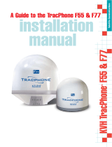
Installation Manual
ver. 1.0
ASE - CIT02

OVERVIEW
Prior to beginning the installation of the Citadel system:
- Take a quick inventory and make sure that you have all of the necessary components.
- Survey your antenna/ADU location with an awareness to 360 degree line-of-site
to horizon and maximum temperature 70° Celsius.
- Plot your cable run and verify lengths, conduit and hole diameters,
and connector ends (female connects to ADU)
- Determine location of Junction Box and POTS cabinet.
SYSTEM COMPONENTS
ASE-MC05G
ComCenter II Outdoor transceiver with GPS and integrated antenna
ASE-MNT20
Universal Mounting Bracket with vibration dampening
ASE-12150T
150' (45m) Composite Cable (ASE-CIT01 package)
ASE-12328T
328' (100m) Composite Cable (ASE-CIT02-EXT package)
ASE-JB03
Junction Box for ADU cable with RJ-11, RJ-45, and power (optionally includes AC/DC adapter)
1 1
1
1
1
1
1
1
1
2
3
4
5
6
7
8
ASE-PS08
Fused DC Cable - if bypassing the AC/DC adapter
ASE-CB-POTS
POTS Phone in Lockable Cabinet with 50’ (15M) RJ-11 cable
ASE-CB-UPS EXT
Uninterrupted Power Supply (UPS) battery backup (optional)
ver. 1.0

RJ-45 ETHERNET (standard CAT5 cable)
2-wire touch tone telephone
in lockable cabinet with 50'
(15m) 2-wire RJ-11 cable
ASE COMPOSITE CABLE WITH
TURRET CONNECTORS
RJ-11 POTS (standard 2-wire RJ-11 cable)
UPS (OPTIONAL)
P/N: ASE-CIT-UPS-EXT
RJ-11 TO
BRIDGE
(OPTIONAL)
LAPTOP or LAN
(OPTIONAL)
ComCenter II Outdoor with GPS
Iridium Sat Phone & Antenna
Input: 24 - 36VDC
Output: Voice (RJ-11 POTS)
Data (RJ-45 Ethernet, Streaming GPS)
ASE-MC05G
ASE-CB-PTS
ENGINE ROOM
(CITADEL SAFE ROOM)
FUNNEL TOP
ASE-12xxxT
150 feet (45m) standard Up to 250'(76m) (Power & Ethernet Data)
[150 ft option can be extended with 20'(6m),
50'(15m), and 100'(30m) lengths]
Up to 7,500'(2285m) (RJ-11 Voice)
Combined Max Cable Lengths
RJ-11 Voice: 8,000' (3Km)
RJ-45 Ethernet data: 400'(122m)
Power: 400'(122m) (18 AWG)
ASE-MNT20
Vibration Dampening
Universal Mounting Bracket
[328 feet (100m) option]
120/240 VAC
120/240 VAC
Junction Box
(ASE-JB03)
+
24VDC
-
Fuse
24V AC/DC
Adapter
(ASE-PS072)
2A
RJ-45
RJ-11
Fused DC Cable
(ASE-PS08)
CITADEL INSTALLATION and WIRING DIAGRAM
ver. 1.0

The Above Deck Unit (MC05G) has the antenna and tranceiver all contained in one unit.
ABOVE DECK UNIT (ADU)
1m (3.2ft)
.15m (.5ft)
above structure
8
clearance angle
clear 360° view
to sky/horizon
THERE ARE SOME CRITICAL INSTALLATION DETAILS BELOW. PLEASE REVIEW CAREFULLY.
1)
Although a funnel installation is recommended as a steath solution,
this device is not sutiable for all funnels. Be sure to install in a
location that does not exceed 70° C or damage can occur.
2) The ADU needs 360° line-of-site to 8° off horizon to be in constant
contact with the satellites. Locate the centerline of the ADU at the
same height as the retaining wall and 1 M inward.
3) The Universal Pipe Mount supports the installation of horizontal or
vertical pipes of 1” to 2” in diameter. Mount the antenna with the
“seam” parallel with the horizon and keep blockage to a minimum.
Once you have identified your preferred location of antenna
installation, adjust the V-Bolts to accommodate either a vertical
or horizontal placement.
12.7 cm
15.3 cm
28 cm
to below deck equipment
Cable Routing and Attachment to the Antenna
Choose the best pathway and route the cable from the antenna to the
Citadel location. If extensions are used, connect these as needed. Care must
be taken when routing the cable. The max connector diameter needs to be
considered when passing through holes or running in conduit. The max bend
radius is important to consider to prevent damaging internal wires.
ver. 1.0
Cable Diameter
Max Connector Size
Max Bend Radius
Max Temperature
.325” (8.26mm)
1.25” (31.75mm)
.98” (25mm)
105°C

The junction box provides the termination point for the ADU cable.
Terminated inside the junction box is POTS (2-wire RJ-11), ethernet (CAT5), and power (24VDC)
Optionally, a 24VDC AC/DC converter can be located in the junction box.
JUNCTION BOX
+ -
Fuse
24V AC/DC
Adapter
(ASE-PS072)
2A
RJ-45
RJ-11
Optional RJ-45 ETHERNET
(standard CAT5 cable)
RJ-11 POTS
(standard 2-wire RJ-11 cable)
120/240 VAC
ASE - 12xxT to ADU
+ -
Fuse
2A
RJ-45
RJ-11
Optional RJ-45 ETHERNET
(standard CAT5 cable)
RJ-11 POTS
(standard 2-wire RJ-11 cable)
Optional 24VCD Direct (fused)
ASE - 12xxT to ADU
OPTION 1: Hook-up from AC
OPTION 2: Hook-up from DC (UPS)
24VDC
9.90”
(251mm)
10.05”
( 255mm)
8.05”
( 204mm)
.31 X .77”
(8 X 20mm)
11.30”
(287mm)
ver. 1.0

The POTS Cabinet connects to the POTS (2-wire RJ-11 port) in the Junction Box.
The POTS Cabinet ships with 50ft (15M) of 2-wire pre-connected to the POTS Cabinet.
This 2-wire is terminated with an RJ-11 header and plugs directly into the RJ-11 port in the Junction Box.
11.45”
(291mm)
11.30”
(287mm)
8.98
(228mm)
5.98”
( 152mm)
POTS CABINET
Hinge - Door opens to the left
Latch
Cable Exit from back
.25” (6.35mm) Thru-hole
ver. 1.0
/