Page is loading ...

1
Conventional Indoor Manual Call Point
Installation Guide
General
The Conventional Indoor Manual Call Point is available in two versions:
Part Number Model Number Product Name
55100-001 MCP1A-R470SF-A071-01 Conventional Indoor Manual Call Point-Red
55100-002 MCP1A-Y470SF-A071-01 Conventional Indoor Manual Call Point-Yellow
Conventional Indoor Manual Call Point
The Conventional Indoor Manual Call Point is supplied with a backbox for surface mounting.
The call point is ‘Type A’ and is suitable for indoor use only. For fl ush mounting, a standard
electrical outlet box with a minimum depth of 25mm is required.
Installation – General
The installation must conform to BS5839: Part 1 (or applicable local codes).
Installation
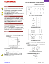
1. Fit the backbox (Fig 1) to the wall.
2. Run the cables into the backbox and connect them to the terminal block as shown in
Fig 2. Ensure that functional earth/screen continuity is maintained.
4
© Apollo Fire Detectors Limited 2010
Apollo Fire Detectors Limited, 36 Brookside Road, Havant, Hants, PO9 1JR, UK
Tel +44 (0)23 9249 2412 Fax +44 (0)23 9249 2754
Email: techsales@apollo-fi re.co.uk Website: www.apollo-fi re.co.uk
39214-587/Issue 1

2
3. Unlock the small front cover by inserting the forked key and pushing it home. Remove key,
slide the cover down and remove the deformable element. Connect the terminal block
as shown in Fig. 2, secure the call point to the backbox and refi t the deformable element
as required. Finally, replace the front cover in the reverse order in which it was removed
and push it up until it locks.
Transparent Hinged Cover (fl ip lid)
To provide additional protection against accidental operation of call points, a transparent
hinged cover, part no. 26729-152 is available, which can be fi tted to the manual call points
included in this guide.
To prevent against malicious activations of call points, locking tags are also avaliable,
part no. 26729-179 (pack of 5).
Please note that the call point does not conform to EN54–11 : 2001 when the hinged cover is
secured with the locking tag.
Commissioning
Test each MCP using the test key provided. Ensure the control panel enters the alarm state.
Wiring Details
All wiring terminals accept solid or stranded cables up to 2.5mm².
Technical data
Maximum Voltage 30VDC
Maximum Switching Current 2A
Alarm Resistor 470Ω
IP rating IP24D
Operating Temperature -10°C to 55°C
Troubleshooting
Before investigating individual units for faults, ensure the system wiring is fault free.
Routine testing
Insert the test key into the hole at the bottom of the call point and push home. Observe
routine test requirements as specifi ed in the applicable local codes.
Resetting
After testing, reset the call point by removing the test key and pushing up the front cover until
it clicks home.
Important Information
The use of lubricants, cleaning solvents or petroleum based products should be avoided.
Do not over tighten fi xing screws.
General Fault Finding
Problem Possible Cause
Control panel reports zone fault Incorrect zone wiring
Detector removed
EOL device missing or incorrectly fi tted
Control panel reports alarm MCP not reset
Test key not removed
Incorrect EOL device
MCP does not activate alarm Incorrect wiring
Incompatible control panel
For further information refer to PP2417.
3
Fig 1 Backbox
87mm
87mm
1
8
765432
++
470 Ω
++
OR
1
8
765432
Fig 2 Terminal block connections
/