H3C S5500-SI Series Operating instructions
- Category
- Networking
- Type
- Operating instructions

Operation Manual – IPv6 Configuration
H3C S5500-SI Series Ethernet Switches Table of Contents
i
Table of Contents
Chapter 1 IPv6 Configuration.......................................................................................................1-1
1.1 IPv6 Overview....................................................................................................................1-1
1.1.1 IPv6 Features..........................................................................................................1-2
1.1.2 Introduction to IPv6 Address...................................................................................1-3
1.1.3 Dual Stack Overview............................................................................................... 1-7
1.1.4 Introduction to IPv6 Neighbor Discovery Protocol .................................................. 1-7
1.1.5 IPv6 PMTU Discovery........................................................................................... 1-10
1.1.6 Introduction to IPv6 DNS....................................................................................... 1-11
1.1.7 Protocol Specifications.......................................................................................... 1-12
1.2 Configuring Basic IPv6 Functions....................................................................................1-12
1.2.1 Configuring the IPv6 Packet Forwarding Function................................................1-12
1.2.2 Configuring an IPv6 Unicast Address...................................................................1-12
1.3 Configuring IPv6 NDP...................................................................................................... 1-14
1.3.1 Configuring a Static Neighbor Entry...................................................................... 1-14
1.3.2 Configuring the Maximum Number of Neighbors Dynamically Learned...............1-15
1.3.3 Configuring Parameters Related to an RA Message............................................1-15
1.3.4 Configuring the Attempts to Send an NS Message for Duplicate Address Detection1-18
1.4 Configuring PMTU Discovery .......................................................................................... 1-19
1.4.1 Configuring a Static PMTU for a Specified IPv6 Address.....................................1-19
1.4.2 Configuring the Aging Time for PMTU.................................................................. 1-19
1.5 Configuring IPv6 TCP Properties.....................................................................................1-19
1.6 Configuring the Maximum Number of IPv6 ICMP Error Packets Sent within a Specified Time
...............................................................................................................................................1-20
1.7 Configuring IPv6 DNS...................................................................................................... 1-21
1.7.1 Configuring Static IPv6 DNS.................................................................................1-21
1.7.2 Configuring Dynamic IPv6 DNS............................................................................1-21
1.8 Displaying and Maintaining IPv6......................................................................................1-22
1.9 IPv6 Configuration Example............................................................................................1-24
Chapter 2 IPv6 Application Configuration..................................................................................2-1
2.1 Introduction to IPv6 Application.........................................................................................2-1
2.2 Ping IPv6............................................................................................................................ 2-1
2.3 Traceroute IPv6 ................................................................................................................. 2-1
2.4 FTP Configuration.............................................................................................................. 2-2
2.4.1 Configuration Prerequisites.....................................................................................2-3
2.4.2 Logging in to the FTP Server.................................................................................. 2-3
2.5 TFTP Configuration ...........................................................................................................2-4
2.5.1 Configuration Preparation....................................................................................... 2-4

Operation Manual – IPv6 Configuration
H3C S5500-SI Series Ethernet Switches Table of Contents
ii
2.5.2 TFTP Configuration.................................................................................................2-4
2.6 IPv6 Telnet.........................................................................................................................2-5
2.6.1 Configuration Prerequisites.....................................................................................2-5
2.6.2 Setting up IPv6 Telnet Connections........................................................................2-5
2.6.3 Displaying and Maintaining IPv6 Telnet..................................................................2-6
2.7 Examples of Typical IPv6 Application Configurations ....................................................... 2-6
2.7.1 Network requirements............................................................................................. 2-6
2.7.2 Network diagram.....................................................................................................2-6
2.7.3 Configuration procedure..........................................................................................2-7
2.8 Troubleshooting IPv6 Application......................................................................................2-8
2.8.1 Unable to Ping a Remote Destination.....................................................................2-8
2.8.2 Unable to Run Traceroute.......................................................................................2-8
2.8.3 Unable to Run FTP .................................................................................................2-9
2.8.4 Unable to Run TFTP...............................................................................................2-9
2.8.5 Unable to Run Telnet..............................................................................................2-9

Operation Manual – IPv6 Configuration
H3C S5500-SI Series Ethernet Switches Chapter 1
IPv6 Configuration
1-1
Chapter 1 IPv6 Configuration
Note:
The descriptions and examples in the text applies to both switches and routers, unless
there is a warning.
When configuring IPv6, go to these sections for information you are interested in:
z IPv6 Overview
z Configuring Basic IPv6 Functions
z Configuring IPv6 NDP
z Configuring PMTU Discovery
z Configuring IPv6 TCP Properties
z Configuring the Maximum Number of IPv6 ICMP Error Packets Sent within a
Specified Time
z Configuring IPv6 DNS
z Displaying and Maintaining IPv6
z IPv6 Configuration Example
1.1 IPv6 Overview
Internet protocol version 6 (IPv6), also called IP next generation (IPng), was designed
by the Internet Engineering Task Force (IETF) as the successor to Internet protocol
version 4 (IPv4).The significant difference between IPv6 and IPv4 is that IPv6
increases the IP address size from 32 bits to 128 bits. This section covers the following
sections:
z IPv6 Features
z Introduction to IPv6 Address
z Dual Stack Overview
z Introduction to IPv6 Neighbor Discovery Protocol
z IPv6 PMTU Discovery
z Introduction to IPv6 DNS
z Protocol Specifications

Operation Manual – IPv6 Configuration
H3C S5500-SI Series Ethernet Switches Chapter 1
IPv6 Configuration
1-2
1.1.1 IPv6 Features
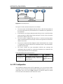
I. Header format simplification
IPv6 cuts down some IPv4 header fields or move them to extension headers to reduce
the load of basic IPv6 headers, thus making IPv6 packet handling simple and improving
the forwarding efficiency. Although the IPv6 address size is four times that of IPv4
addresses, the size of basic IPv6 headers is only twice that of IPv4 headers (excluding
the Options field).
Ver
Traffic
class
Flow label
Payload length
Next
header
Hop limit
Source
12
address
8 bits
Destinat
12
ion address
8 bits
Ver IHL Total length
Identification F Fragment offset
TTL
Source address (32 bits)
TOS
Header checksum
Destination address (32 bits)
Protocol
IPv4 header
IPv
6 header
Options Padding
0 7 15 31 0 7 15 31
Figure 1-1 Comparison between IPv4 header format and IPv6 header format
II. Adequate address space
The source IPv6 address and the destination IPv6 address are both 128 bits (16 bytes)
long.IPv6 can provide 3.4 x 10
38
addresses to completely meet the requirements of
hierarchical address division as well as allocation of public and private addresses.
III. Hierarchical address structure
IPv6 adopts the hierarchical address structure to quicken route search and reduce the
system source occupied by the IPv6 routing table by means of route aggregation.
IV. Automatic address configuration
To simplify the host configuration, IPv6 supports stateful address configuration and
stateless address configuration. Stateful address configuration means that a host
acquires an IPv6 address and related information from the server (for example, DHCP
server). Stateless address configuration means that the host automatically configures
an IPv6 address and related information based on its own link-layer address and the
prefix information issued by the router. In addition, a host can generate a link-local
address based on its own link-layer address and the default prefix (FE80::/64) to
communicate with other hosts on the link.

Operation Manual – IPv6 Configuration
H3C S5500-SI Series Ethernet Switches Chapter 1
IPv6 Configuration
1-3
V. Built-in security
IPv6 uses IPSec as its standard extension header to provide end-to-end security. This
feature provides a standard for network security solutions and improves the
interoperability between different IPv6 applications.
VI. Support for QoS
The Flow Label field in the IPv6 header allows the device to label packets in a flow and
provide special handling for these packets.
VII. Enhanced neighbor discovery mechanism
The IPv6 neighbor discovery protocol means a group of Internet control message
protocol version 6 (ICMPv6) messages manages the interaction between neighbor
nodes (nodes on the same link).The group of ICMPv6 messages takes the place of
address resolution protocol (ARP), Internet control message protocol version 4
(ICMPv4), and ICMPv4 redirection messages to provide a series of other functions.
VIII. Flexible extension headers
IPv6 cancels the Options field in IPv4 packets but introduces multiple extension
headers. In this way, IPv6 enhances the flexibility greatly to provide scalability for IP
while improving the processing efficiency. The Options field in IPv4 packets contains
only 40 bytes, while the size of IPv6 extension headers is restricted by that of IPv6
packets.
1.1.2 Introduction to IPv6 Address
I. IPv6 address format
An IPv6 address is represented as a series of 16-bit hexadecimals, separated by
colons. An IPv6 address is divided into eight groups, 16 bits of each group are
represented by four hexadecimal numbers which are separated by colons, for example,
2001:0000:130F:0000:0000:09C0:876A:130B.
To simplify the representation of IPv6 addresses, zeros in IPv6 addresses can be
handled as follows:
z Leading zeros in each group can be removed. For example, the above-mentioned
address can be represented in shorter format as
2001:0:130F:0:0:9C0:876A:130B.
z If an IPv6 address contains two or more consecutive groups of zeros, they can
replaced by the double-colon :: option. For example, the above-mentioned
address can be represented in the shortest format as
2001:0:130F::9C0:876A:130B.

Operation Manual – IPv6 Configuration
H3C S5500-SI Series Ethernet Switches Chapter 1
IPv6 Configuration
1-4
Caution:
The double-colon :: can be used only once in an IPv6 address. Otherwise, the device is
unable to determine how many zeros the double-colon represents when converting it to
zeros to restore the IPv6 address to a 128-bit address.
An IPv6 address consists of two parts: address prefix and interface ID. The address
prefix and the interface ID are respectively equivalent to the network ID to the host ID in
an IPv4 address.
An IPv6 address prefix is written in IPv6-address/prefix-length notation, where
IPv6-address is an IPv6 address in any of the notations and prefix-length is a decimal
number indicating how many bits from the utmost left of an IPv6 address are the
address prefix.
II. IPv6 address classification
IPv6 addresses mainly fall into three types: unicast address, multicast address and
anycast address.
z Unicast address: An identifier for a single interface, similar to an IPv4 unicast
address .A packet sent to a unicast address is delivered to the interface identified
by that address.
z Multicast address: An identifier for a set of interfaces (typically belonging to
different nodes), similar to an IPv4 multicast address. A packet sent to a multicast
address is delivered to all interfaces identified by that address.
z Anycast address: An identifier for a set of interfaces (typically belonging to
different nodes).A packet sent to an anycast address is delivered to one the
interfaces identified by that address (the nearest one, according to the routing
protocols’ measure of distance).
Note:
There are no broadcast addresses in IPv6. Their function is superseded by multicast
addresses.
The type of an IPv6 address is designated by the first several bits called format prefix.
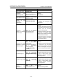
Table 1-1 lists the mapping between major address types and format prefixes.

Operation Manual – IPv6 Configuration
H3C S5500-SI Series Ethernet Switches Chapter 1
IPv6 Configuration
1-5
Table 1-1 Mapping between address types and format prefixes
Type Format prefix (binary) IPv6 prefix ID
Unassigned
address
00...0 (128 bits) ::/128
Loopback
address
00...1 (128 bits) ::1/128
Link-local
address
1111111010 FE80::/10
Site-local
address
1111111011 FEC0::/10
Unicast
address
Global unicast
address
other forms
—
Multicast address
11111111 FF00::/8
Anycast address
Anycast addresses are taken from unicast address
space and are not syntactically distinguishable
from unicast addresses.
III. Unicast address
There are several forms of unicast address assignment in IPv6, including aggregatable
global unicast address, link-local address, and site-local address.
z The aggregatable global unicast address, equivalent to an IPv4 public address, is
used for aggregatable links and provided for network service providers. The
structure of such a type of address allows efficient routing aggregation to restrict
the number of global routing entries.
z The link-local address is used for communication between link-local nodes in
neighbor discovery and stateless autoconfiguration. Routers must not forward any
packets with link-local source or destination addresses to other links.
z IPv6 unicast site-local addresses are similar to private IPv4 addresses. Routers
must not forward any packets with site-local source or destination addresses
outside of the site (equivalent to a private network).
z Loopback address: The unicast address 0:0:0:0:0:0:0:1 (represented in shorter
format as ::1) is called the loopback address and may never be assigned to any
physical interface. Like the loopback address in IPv4, it may be used by a node to
send an IPv6 packet to itself.
z Unassigned address: The unicast address :: is called the unassigned address and
may not be assigned to any node. Before acquiring a valid IPv6 address, a node
may fill this address in the source address field of an IPv6 packet, but may not use
it as a destination IPv6 address.

Operation Manual – IPv6 Configuration
H3C S5500-SI Series Ethernet Switches Chapter 1
IPv6 Configuration
1-6
IV. Multicast address
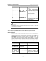
Multicast addresses listed in Table 1-2 are reserved for special purpose.
Table 1-2 Reserved IPv6 multicast addresses
Address Application
FF01::1 Node-local scope all-nodes multicast address
FF02::1 Link-local scope all-nodes multicast address
FF01::2 Node-local scope all-routers multicast address
FF02::2 Link-local scope all-routers multicast address
FF05::2 Site-local scope all-routers multicast address
Besides, there is another type of multicast address: solicited-node address. The
solicited-node multicast address is used to acquire the link-layer addresses of neighbor
nodes on the same link and is also used for duplicate address detection. Each IPv6
unicast or anycast address has one corresponding solicited-node address. The format
of a solicited-node multicast address is as follows:
FF02:0:0:0:0:1:FFXX:XXXX
Where, FF02:0:0:0:0:1:FF is permanent and consists of 104 bits, and XX:XXXX is the
last 24 bits of an IPv6 address.
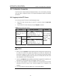
V. Interface identifier in IEEE EUI-64 format
Interface identifiers in IPv6 unicast addresses are used to identify interfaces on a link
and they are required to be unique on that link. Interface identifiers in IPv6 unicast
addresses are currently required to be 64 bits long. An interface identifier is derived
from the link-layer address of that interface. Interface identifiers in IPv6 addresses are
64 bits long, while MAC addresses are 48 bits long. Therefore, the hexadecimal
number FFFE needs to be inserted in the middle of MAC addresses (behind the 24
high-order bits).To ensure the interface identifier obtained from a MAC address is
unique, it is necessary to set the universal/local (U/L) bit (the seventh high-order bit) to
“1”.Thus, an interface identifier in EUI-64 format is obtained.

Operation Manual – IPv6 Configuration
H3C S5500-SI Series Ethernet Switches Chapter 1
IPv6 Configuration
1-7
01011 11001101
0000 10101011 11001101
0000 10101011 11001101
00000000 00010010 00110100 00000000 101
00000000 00010010 00110100 11111111 11111110 0000
0012-3400-ABCD
00000010 00010010 00110100 11111111 11111110 0000
0212:34FF:FE00:ABCD
MAC address:
Represented in binary:
Insert FFFE:
Set U/L bit:
EUI-64 address:
Figure 1-2 Convert a MAC address into an EUI-64 address
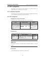
1.1.3 Dual Stack Overview
A network node that supports both IPv4 and IPv6 is called a dual stack node. A dual
stack node configured with an IPv4 and an IPv6 addresses can have both IPv4 and
IPv6 packets transmitted.
For an upper layer application supporting both IPv4 and IPv6, either TCP or UDP can
be selected at the transport layer, while at network layer, IPv6 stack is peferred.
Figure
1-3
illustrates the IPv4/IPv6 dual stack in relation to the IPv4 stack.
IPv4
IPv4/IPv6
TCP UDP
IPv6
application
Ethernet
Protoc
0x0800
ol ID:
Protocol ID:
0x86DD
IPv4
TCP UDP
IPv4 application
Ethernet
Protocol ID:
0x0800
IPv4 stack Dual
stack
k
Figure 1-3 IPv4/IPv6 dual stack in relation to IPv4 Stac
1.1.4 Introduction to IPv6 Neighbor Discovery Protocol
The IPv6 neighbor discovery protocol (NDP) uses five types of ICMPv6 messages to
implement the following functions:
z Address resolution
z Neighbor unreachability detection
z Duplicate address detection
z Router/prefix discovery and address autoconfiguration
z Redirection
Table 1-3 lists the types and functions of ICMPv6 messages used by the NDP.

Operation Manual – IPv6 Configuration
H3C S5500-SI Series Ethernet Switches Chapter 1
IPv6 Configuration
1-8
Table 1-3 Types and functions of ICMPv6 messages
ICMPv6 message Function
Used to acquire the link-layer address of a neighbor
Used to verify whether the neighbor is reachable
Neighbor solicitation
(NS) message
Used to perform a duplicate address detection
Used to respond to a neighbor solicitation message
Neighbor advertisement
(NA) message
When the link layer changes, the local node initiates a
neighbor advertisement message to notify neighbor
nodes of the node information change.
Router solicitation (RS)
message
After started, a host sends a router solicitation message
to request the router for an address prefix and other
configuration information for the purpose of
autoconfiguration.
Used to respond to a router solicitation message
Router advertisement
(RA) message
With the RA message suppression disabled, the router
regularly sends a router advertisement message
containing information such as address prefix and flag
bits
Redirect message
When a certain condition is satisfied, the default gateway
sends a redirect message to the source host so that the
host can reselect a correct next hop router to forward
packets.
The NDP mainly provides the following functions:
I. Address resolution
Similar to the ARP function in IPv4, a node acquires the link-layer address of neighbor
nodes on the same link through NS and NA messages.
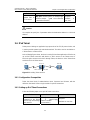
Figure 1-4 shows how node A
acquires the link-layer address of node B.
NS
NA
ICMP Type = 135
Src = A
Dst = solicited-node multicast of B
NS
NA
Data = link-layer address of A
ICMP Type
Src = B
Dst = A
Data = link
AB
= 136
-layer address of B
n
Figure 1-4 Address resolutio
The address resolution procedure is as follows:

Operation Manual – IPv6 Configuration
H3C S5500-SI Series Ethernet Switches Chapter 1
IPv6 Configuration
1-9
1) Node A multicasts an NS message. The source address of the NS message is the
IPv6 address for the interface of node A and the destination address is the
solicited-node multicast address of node B. The NS message contains the
link-layer address of node A.
2) After receiving the NS message, node B judges whether the destination address
of the packet is the corresponding solicited-node multicast address of its own IPv6
address. If yes, node B returns an NA message containing the link-layer address
of node B.
3) Node A acquires the link-layer address of node B fro the NA message. After that,
node A and node B can communicate.
II. Neighbor unreachability detection
After node A acquires the link-layer address of its neighbor node B, node A can verify
whether node B is reachable according to NS and NA messages.
1) Node A sends an NS message whose destination address is the IPv6 address of
node B.
2) If node A receives an NA message from node B, node A considers that node B is
reachable. Otherwise, node B is unreachable.
III. Duplicate address detection
After node A acquires an IPv6 address, it should perform the duplicate address
detection to determine whether the address is being used by other nodes (similar to the
gratuitous ARP function).The duplication address detection is accomplished through
NS and NA messages. Figure shows the duplicate address detection procedure.
NS
NA
ICMP Type = 135
Src = ::
Dst = FF02::1:FF00:1
NS
NA
Data = 2000::1
ICMP Ty
Src = 20
Dst = FF02::1
Target A
AB
pe = 136
00::1
ddress = 2000::1
n
Figure 1-5 Duplicate address detectio
The duplicate address detection procedure is as follows:
1) Node A sends an NS message whose source address is the unassigned address ::
and destination address is the corresponding solicited-node multicast address of
the IPv6 address to be detected. The NS message contains the IPv6 address.
2) If node B uses this IPv6 address, node B returns an NA message. The NA
message contains the IPv6 address of node B.

Operation Manual – IPv6 Configuration
H3C S5500-SI Series Ethernet Switches Chapter 1
IPv6 Configuration
1-10
3) Node A learns that the IPv6 address is being used by node B after receiving the NA
message from node B. Otherwise, node B is not using the IPv6 address and node
A can use it.
IV. Router/prefix discovery and address autoconfiguration
Router/prefix discovery means that a host acquires the neighbor router, the prefix of the
network where the router is located, and other configuration parameters from the
received RA message.
Stateless address autoconfiguration means that a host automatically configure an IPv6
address according to the information obtained through router/prefix discovery.
The router/prefix discovery and address autoconfiguration is implemented through RS
and RA messages. The router/prefix discovery and address autoconfiguration
procedure is as follows:
1) After started, a host sends an RS message to request the router for the address
prefix and other configuration information for the purpose of autoconfiguration.
2) The router returns an RA message containing information such as address prefix
and flag bits. (The router also regularly sends an RA message.)
3) The host automatically configures an IPv6 address and other information for its
interface according to the address prefix and other configuration parameters in the
RA message.
V. Redirection
When a host is started, its routing table may contain only the default route to the
gateway. When certain conditions are satisfied, the gateway sends an ICMPv6 redirect
message to the source host so that the host can select a better next hop router to
forward packets (similar to the ICMP redirection function in IPv4).
The gateway will send an IPv6 ICMP redirect message when the following conditions
are satisfied:
z The receiving interface and the forwarding interface are the same.
z The selected route itself is not created or modified by an IPv6 ICMP redirect
message.
z The selected route is not the default route.
z The forwarded IPv6 packet does not contain any extension header carrying the
routing information of intermediate nodes on the forwarding path.
1.1.5 IPv6 PMTU Discovery
The links that a packet passes from the source to the destination may have different
MTUs. In IPv6, when the packet size exceeds the MTU of a link, the packet will be
fragmented at the source so as to reduce the processing pressure of the forwarding
device and utilize network resources rationally.

Operation Manual – IPv6 Configuration
H3C S5500-SI Series Ethernet Switches Chapter 1
IPv6 Configuration
1-11
The path MTU (PMTU) discovery mechanism is to find the minimum MTU on the path
from the source to the destination.
Figure 1-6 shows the working procedure of the
PMTU discovery.
PC
MTU=1500 MTU=1500 MTU=1350 M
PC
TU=1400
Source
Packet with MTU=1500
ICMP error:packet too big;use MTU=1350
Packet with MTU=1350
Packet received
Destination
y
Figure 1-6 Working procedure of the PMTU discover
The working procedure of the PMTU discovery is as follows:
1) The source host uses its MTU to fragment packets and then sends them to the
destination host.
2) If the MTU supported by the packet forwarding interface is less than the size of a
packet, the forwarding device will discard the packet and return an ICMPv6 error
packet containing the interface MTU to the source host.
3) After receiving the ICMPv6 error packet, the source host uses the returned MTU to
fragment the packet again and then sends it.
4) Step 2 to step 3 are repeated until the destination host receives the packet. In this
way, the minimum MTU on the path from the source host to the destination host is
determined.
1.1.6 Introduction to IPv6 DNS
In the IPv6 network, a domain name system (DNS) supporting IPv6 converts domain
names into IPv6 addresses. Different from an IPv4 DNS, an IPv6 DNS converts domain
names into IPv6 addresses, instead of IPv4 addresses.
However, just like an IPv4 DNS, an IPv6 DNS also covers static domain name
resolution and dynamic domain name resolution. The function and implementation of
these two types of domain name resolution are the same as those of an IPv4 DNS. For
details, refer to DNS module.
Usually, the DNS server connecting IPv4 and IPv6 networks contain not only A records
(IPv4 addresses) but also AAAA records (IPv6 addresses). The DNS server can
convert domain names into IPv4 addresses or IPv6 addresses. In this way, the DNS
server has the functions of both IPv6 DNS and IPv4 DNS.

Operation Manual – IPv6 Configuration
H3C S5500-SI Series Ethernet Switches Chapter 1
IPv6 Configuration
1-12
1.1.7 Protocol Specifications
Protocol specifications related to IPv6 include:
z RFC 1881: IPv6 Address Allocation Management
z RFC 1887: An Architecture for IPv6 Unicast Address Allocation
z RFC 1981: Path MTU Discovery for IP version 6
z RFC 2375: IPv6 Multicast Address Assignments
z RFC 2460: Internet Protocol, Version 6 (IPv6) Specification.
z RFC 2461: Neighbor Discovery for IP Version 6 (IPv6)
z RFC 2462: IPv6 Stateless Address Autoconfiguration
z RFC 2463: Internet Control Message Protocol (ICMPv6) for the Internet Protocol
Version 6 (IPv6) Specification
z RFC 2464: Transmission of IPv6 Packets over Ethernet Networks
z RFC 2526: Reserved IPv6 Subnet Anycast Addresses
z RFC 3307: Allocation Guidelines for IPv6 Multicast Addresses
z RFC 3513: Internet Protocol Version 6 (IPv6) Addressing Architecture
z RFC 3596: DNS Extensions to Support IP Version 6
1.2 Configuring Basic IPv6 Functions
1.2.1 Configuring the IPv6 Packet Forwarding Function
Before IPv6-related configurations, you must enable the IPv6 packet forwarding
function for an interface. Otherwise, the interface cannot forward IPv6 packets even if
an IPv6 address is configured, resulting in interworking failures in the IPv6 network.
Follow these steps to configure the IPv6 packet forwarding function:
To do... Use the command... Remarks
Enter system view
system-view
—
Enable the IPv6 packet
forwarding function
ipv6
Required
Disabled by default.
1.2.2 Configuring an IPv6 Unicast Address
IPv6 site-local addresses and aggregatable global unicast addresses can be
configured in either of the following ways:
z EUI-64 format: When the EUI-64 format is adopted to form IPv6 addresses, the
IPv6 address prefix of an interface is the configured prefix and the interface
identifier is derived from the link-layer address of the interface.
z Manual configuration: IPv6 site-local addresses or aggregatable global unicast
addresses are configured manually.

Operation Manual – IPv6 Configuration
H3C S5500-SI Series Ethernet Switches Chapter 1
IPv6 Configuration
1-13
IPv6 link-local addresses can be acquired in either of the following ways:
z Automatic generation: The device automatically generates a link-local address for
an interface according to the link-local address prefix (FE80::/64) and the
link-layer address of the interface.
z Manual assignment: IPv6 link-local addresses can be assigned manually.
Follow these steps to configure an IPv6 unicast address:
To do... Use the command... Remarks
Enter system view
system-view
—
Enter interface view
interface interface-type
interface-number
—
Manually
assign an
IPv6 address
ipv6 address
{ ipv6-address prefix-length
|
ipv6-address/prefix-length }
Configure
an IPv6
aggregatabl
e global
unicast
address or
site-local
address
Adopt the
EUI-64 format
to form an
IPv6 address
ipv6 address
ipv6-address/prefix-length
eui-64
Alternative
By default, no
site-local address or
aggregatable global
unicast address is
configured for an
interface.
Note that the prefix
length specified by
the prefix-length
argument cannot be
greater than 64.
Automatically
generate a
link-local
address
ipv6 address auto
link-local
Configure
an IPv6
link-local
address
Manually
assign a
link-local
address for an
interface.
ipv6 address ipv6-address
link-local
Optional
By default, after an
IPv6 site-local
address or
aggregatable global
unicast address is
configured for an
interface, a link-local
address will be
generated
automatically.

Operation Manual – IPv6 Configuration
H3C S5500-SI Series Ethernet Switches Chapter 1
IPv6 Configuration
1-14
Note:
z After an IPv6 site-local address or aggregatable global unicast address is
configured for an interface, a link-local address will be generated automatically. The
automatically generated link-local address is the same as the one generated by
using the ipv6 address auto link-local command. If a link-local address is
manually assigned to an interface, this link-local address takes effect. If the
manually assigned link-local address is deleted, the automatically generated
link-local address takes effect.
z The manual assignment takes precedence over the automatic generation. That is, if
you first adopt the automatic generation and then the manual assignment, the
manually assigned link-local address will overwrite the automatically generated one.
If you first adopt the manual assignment and then the automatic generation, the
automatically generated link-local address will not take effect and the link-local
address of an interface is still the manually assigned one. You must delete the
manually assigned link-local address before adopting the automatic generation.
z You must have carried out the ipv6 address auto link-local command before you
carry out the undo ipv6 address auto link-local command. However, if an IPv6
site-local address or aggregatable global unicast address is already configured for
an interface, the interface still has a link-local address because the system
automatically generates one for the interface. If no IPv6 site-local address or
aggregatable global unicast address is configured, the interface has no link-local
address.
z You can configure IPv6 addresses for VLAN interface and LoopBack interface on
S5500-SI Series Ethernet Switches.
z The prefix length can only be 128 bits when the aggregatable global unicast
address(es) or site-local address(es) is configured in the LoopBack interface view.
1.3 Configuring IPv6 NDP
1.3.1 Configuring a Static Neighbor Entry
The IPv6 address of a neighbor node can be resolved into a link-layer address
dynamically through NS and NA messages or statically through manual configuration.
The device uniquely identifies a static neighbor entry according to the IPv6 address and
the layer 3 interface ID.
Configure the corresponding IPv6 address and link-layer address for a layer 3
interface.
Follow these steps to configure a static neighbor entry:

Operation Manual – IPv6 Configuration
H3C S5500-SI Series Ethernet Switches Chapter 1
IPv6 Configuration
1-15
To do... Use the command... Remarks
Enter system
view
system-view
—
Configure a
static neighbor
entry
ipv6 neighbor ipv6-address
mac-address { vlan-id port-type
port-number | interface interface-type
interface-number }
Required
1.3.2 Configuring the Maximum Number of Neighbors Dynamically Learned
The device can dynamically acquire the link-layer address of a neighbor node through
NS and NA messages. Too large a neighbor table from which neighbor entries can be
dynamically acquired may lead to the forwarding performance degradation of the
device. Therefore, you can restrict the size of the neighbor table by setting the
maximum number of neighbors that an interface can dynamically learn. When the
number of dynamically learned neighbors reaches the threshold, the interface will stop
learning neighbor information.
Follow these steps to configure the maximum number of neighbors dynamically
learned:
To do… Use the command… Remarks
Enter system view
system-view
—
Enter interface view
interface interface-type
interface-number
—
Configure the
maximum number of
neighbors dynamically
learned by an interface
ipv6 neighbors
max-learning-num number
Optional
The default value is
1024
1.3.3 Configuring Parameters Related to an RA Message
You can configure whether the interface sends an RA message, the interval for sending
RA messages, and parameters in RA messages. After receiving an RA message, a
host can use these parameters to perform corresponding operations.
Table 1-4 lists the
configurable parameters in an RA message and their descriptions.
Table 1-4 Parameters in an RA message and their descriptions
Parameters Description
Cur hop limit
When sending an IPv6 packet, a host uses the value of this
parameter to fill the Hop Limit field in IPv6 headers. Meanwhile,
the value of this parameter is equal to the value of the Cur Hop
Limit field in response messages of the device.

Operation Manual – IPv6 Configuration
H3C S5500-SI Series Ethernet Switches Chapter 1
IPv6 Configuration
1-16
Parameters Description
Prefix
information
options
After receiving the prefix information, the hosts on the same link
can perform stateless autoconfiguration operations.
M flag
This field determines whether hosts use the stateful
autoconfiguration to acquire IPv6 addresses.
If the M flag is set to 1, hosts use the stateful autoconfiguration
to acquire IPv6 addresses. Otherwise, hosts use the stateless
autoconfiguration to acquire IPv6 addresses, that is, hosts
configure IPv6 addresses according to their own link-layer
addresses and the prefix information issued by the router.
O flag
This field determines whether hosts use the stateful
autoconfiguration to acquire information other than IPv6
addresses.
If the O flag is set to 1, hosts use the stateful autoconfiguration
(for example, DHCP server) to acquire information other than
IPv6 addresses. Otherwise, hosts use the stateless
autoconfiguration to acquire information other than IPv6
addresses.
Router lifetime
This field is used to set the lifetime of the router that sends RA
messages to serve as the default router of hosts. According to
the router lifetime in the received RA messages, hosts
determine whether the router sending RA messages can serve
as the default router of hosts.
Retrans timer
If a node fails to receive a response message within the
specified time after sending an NS message, the node will
retransmit it.
Reachable time
After the neighbor unreachability detection shows that a
neighbor is reachable, a node considers the neighbor is
reachable within the reachable time. If the node needs to send a
packet to a neighbor after the reachable time expires, the node
will again confirm whether the neighbor is reachable.
Note:
The values of the retrans timer field and the reachable time field configured for an
interface are sent to hosts via RA messages. Furthermore, the interface sends NS
messages at intervals of the value of the retrans timer field and considers a neighbor
reachable in the time of the value of the reachable time field.
Follow these steps to configure parameters related to an RA message:

Operation Manual – IPv6 Configuration
H3C S5500-SI Series Ethernet Switches Chapter 1
IPv6 Configuration
1-17
To do… Use the command… Remarks
Enter system view
system-view
—
Configure the
current hop limit
ipv6 nd hop-limit value
Optional
64 by default.
Enter interface view
interface interface-type
interface-number
—
Disable the RA
message
suppression.
undo ipv6 nd ra halt
Optional
By default, RA messages are
suppressed.
Configure the
interval for sending
RA messages
ipv6 nd ra interval
max-interval-value
min-interval-value
Optional
By default, the maximum interval
for sending RA messages is 600
seconds, and the minimum
interval is 200 seconds.
The device sends RA messages
at intervals of a random value
between the maximum interval
and the minimum interval.
The minimum interval should be
less than or equal to 0.75 times
the maximum interval.
Configure the prefix
information options
in RA messages
ipv6 nd ra prefix
{ ipv6-address
prefix-length |
ipv6-address/prefix-leng
th } valid-lifetime
preferred-lifetime
[ no-autoconfig |
off-link ]*
Optional
By default, no prefix information
is configured in RA messages
and the IPv6 address of the
interface sending RA messages
is used as the prefix information.
Set the M flag to 1
ipv6 nd autoconfig
managed-address-flag
Optional
By default, the M flag bit is set to
0, that is, hosts acquire IPv6
addresses through stateless
autoconfiguration.
Set the O flag bit to
1.
ipv6 nd autoconfig
other-flag
Optional
By default, the O flag bit is set to
0, that is, hosts acquire other
information through stateless
autoconfiguration.
Configure the router
lifetime in RA
messages
ipv6 nd ra
router-lifetime value
Optional
1,800 seconds by default.

Operation Manual – IPv6 Configuration
H3C S5500-SI Series Ethernet Switches Chapter 1
IPv6 Configuration
1-18
To do… Use the command… Remarks
Set the retrans timer
ipv6 nd ns
retrans-timer value
Optional
By default, the local interface
sends NS messages at intervals
of 1,000 milliseconds and the
Retrans Timer field in RA
messages sent by the local
interface is equal to 0.
Set the reachable
time
ipv6 nd nud
reachable-time value
Optional
By default, the neighbor
reachable time on the local
interface is 30,000 milliseconds
and the Reachable Timer field in
RA messages is 0.
Caution:
The maximum interval for sending RA messages should be less than or equal to the
router lifetime in RA messages.
1.3.4 Configuring the Attempts to Send an NS Message for Duplicate
Address Detection
The device sends a neighbor solicitation (NS) message for duplicate address detection.
If the device does not receive a response within a specified time (set by the ipv6 nd ns
retrans-timer value command), the device continues to send an NS message. If the
device still does not receive a response after the number of attempts to send an NS
message reaches the maximum, the device judges the acquired address is available
Follow these steps to configure the attempts to send an NS message for duplicate
address detection:
To do… Use the command… Remarks
Enter system view
system-view
—
Enter interface view
interface
interface-type
interface-number
—
Configure the
attempts to send an
NS message for
duplicate address
detection
ipv6 nd dad attempts
value
Optional
1 by default. When the value
argument is set to 0, the
duplicate address detection is
disabled.
Page is loading ...
Page is loading ...
Page is loading ...
Page is loading ...
Page is loading ...
Page is loading ...
Page is loading ...
Page is loading ...
Page is loading ...
Page is loading ...
Page is loading ...
Page is loading ...
Page is loading ...
Page is loading ...
Page is loading ...
Page is loading ...
Page is loading ...
Page is loading ...
-
 1
1
-
 2
2
-
 3
3
-
 4
4
-
 5
5
-
 6
6
-
 7
7
-
 8
8
-
 9
9
-
 10
10
-
 11
11
-
 12
12
-
 13
13
-
 14
14
-
 15
15
-
 16
16
-
 17
17
-
 18
18
-
 19
19
-
 20
20
-
 21
21
-
 22
22
-
 23
23
-
 24
24
-
 25
25
-
 26
26
-
 27
27
-
 28
28
-
 29
29
-
 30
30
-
 31
31
-
 32
32
-
 33
33
-
 34
34
-
 35
35
-
 36
36
-
 37
37
-
 38
38


H3C S5500-SI Series Operating instructions
- Category
- Networking
- Type
- Operating instructions
Ask a question and I''ll find the answer in the document
Finding information in a document is now easier with AI
Related papers
-
H3C S9500 Series Operating instructions
-
H3C s5820x series Configuration manual
-
-
-
H3C WA2200 Series Command Reference Manual
-
-
-
H3C S7500 Series Operating instructions
-
-
Other documents
-
Dahua DH-S5500-24GF4XF-E User manual
-
Supermicro L3 User manual
-
HP (Hewlett-Packard) 2900 User manual
-
3com 3CRS48G-48P-91 Configuration manual
-
Avaya IPv6 User manual
-
Juniper IPV6 - CONFIGURATION GUIDE V11.1.X Configuration manual
-
-
-
3com 4210G NT Configuration manual
-
Dell Networking S3100 Series Owner's manual