Page is loading ...
Owner's Manual
ICRAFI",'SMAN+I
42"- 2 STAGE SNOW THROWER
TRACTO R ATTAC HMENT
Model No. 486.248531
CAUTION:
Before using this product, read
this manual and follow all
Safety Rules and
Operating Instructions.
• Safety
• Assembly
• Operation
• Maintenance
• Parts
IMPORTANT - READ THIS FIRST!!!
For Missing Parts or Assembly Questions
Please Call 217-728-8388
Mon.-Fri. 7 am - 5 pm CST.
Missing parts will be sent UPS in 24 hours directly to your home.
Sears, Roebuck and Co., Hoffman Estates, IL 60179 U.S.A.
www.sears.com/craftsman
PRINTED IN U.S.A. FORM NO. 48935 (7/03)
ACCESSORIES ........................................................... 2
SAFETY RULES .......................................................... 3
FULL SIZE HARDWARE CHART ................................. 4
CARTON CONTENTS ................................................. 5
ASSEMBLY ................................................................. 5
OPERATION ............................................................. 15
MAINTENANCE ......................................................... 16
SERVICE AND ADJUSTMENTS ................................ 17
STORAGE ................................................................. 18
TROUBLESHOOTING ............................................... 18
REPAIR PARTS ILLUSTRATION ......................... 20,22
REPAIR PARTS LIST ........................................... 21,23
SLOPE GUIDE .......................................................... 27
PARTS ORDERING/SERVICE ................ BACK COVER
LIMITED ONE YEAR WARRANTY ON 42" 2-STAGE SNOW THROWER
For one year from the date of purchase, when this snow thrower is maintained and lubricated according to the operating
and maintenance instructionsinthe owner's manual, Sears willrepair any defect in materialor workmanship free ofcharge.
If this snow thrower is used for commercial or rental purposes, this warranty applies for only 90 days from the date of
purchase.
This warranty does not cover repairs necessary because of operator negligence or abuse, including thefailure to maintain
the equipment according to instructions contained in the owner's manual.
WARRANTY SERVICE IS AVAILABLE BY CONTACTING THE NEAREST SEARS SERVICE CENTER/DEPARTMENT
IN THE UNITED STATES.
This warranty applies only while this product is in the United States.
This warranty gives you specific legal rights, and you may also have other rights which vary from state to state.
Sears, Roebuck and Co. D/817 WA. Hoffman Estates, Chicago, IL 60179
These accessories were available when the unit was purchased. They are also available at most Sears retail outlets
and service centers. Most Sears stores can order repair parts for you when you provide the model numbers of your
tractor and snow thrower.
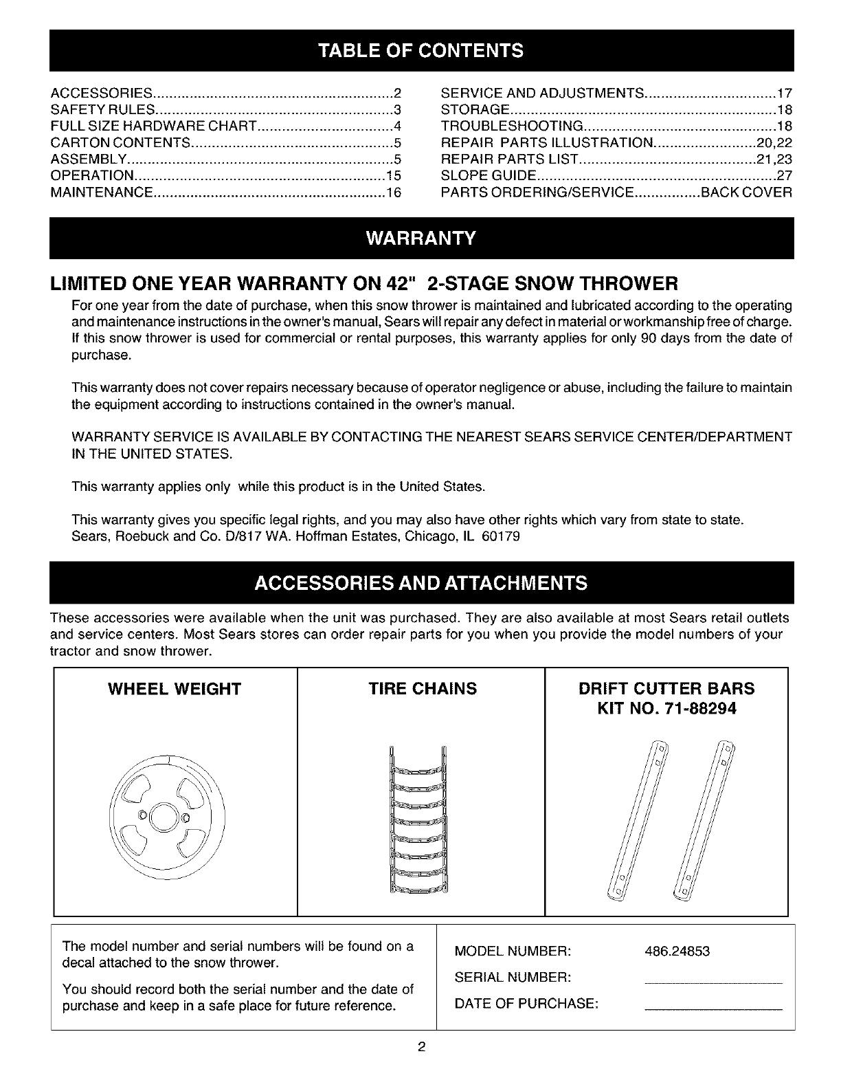
WHEEL WEIGHT TIRE CHAINS DRIFT CUTTER BARS
KIT NO. 71-88294
The model number and serial numbers will be found on a
decal attached to the snow thrower.
You should record both the serial number and the date of
purchase and keep in a safe place for future reference.
MODEL NUMBER:
SERIAL NUMBER:
DATE OF PURCHASE:
486.24853
2

Anypowerequipmentcancauseinjuryifoperatedimproperlyorifthe userdoesnotunderstandhowtooperate
theequipment.Exercisecautionatall times,whenusingpowerequipment.
• Readthisowner'smanualcarefullyandknowhow
tooperateyoursnowthrowerandhowtostopthe
unitanddisengagethecontrolsquickly.
• Neverallowchildrentooperatetheequipment.
• Neverallowadultstooperatetheequipment
withoutproperinstruction.
• Keeptheareaofoperationclearof allpersons,
especiallysmallchildren,andpets.
• Thoroughlyinspecttheareawheretheequipment
istobeusedandremovealldoormats,sleds,
boards,wiresandotherforeignobjects.
• Disengageallclutchesandshiftintoneutralbefore
startingengine.
• Donotoperateequipmentwithoutwearingad-
equatewinteroutergarments.
• Wearsubstantialfootwearwhichwillprotectfeet
andimprovefootingonslipperysurfaces.
• Checkfuelbeforestartingtheengine.Donot
removethefuelcaporfillthefueltankwhilethe
engineisrunningorhot.Donotfill thefueltank
indoors.Gasolineisanextremelyflammablefuel.
• Makesurethesnowthrowerheightisadjustedto
clearthetypesurfaceit willbeusedon.
• Donotusethesnowthrowerwithouttherear
weightattachedtothetractor.
• Nevermakeanyadjustmentswhiletheengineis
running.
• Alwayswearsafetyglassesoreyeshieldduring
operationorwhileperformingandadjustmentor
repair.
• Donotplacehandorfeetnearrotatingparts.Keep
clearofthedischargeopeningatalltimes.
• Useextremecautionwhenoperatingonorcrossing
gravelsurfaces.
• Donotcarrypassengers.
• Afterstrikingaforeignobject,stoptheengine,
removethewirefromthesparkplugandthen
thoroughlyinspectthesnowthrowerfordamage.
Repairanydamagebeforerestartingandoperating
thesnowthrower.
• Ifthesnowthrowerstartstovibrateabnormally,
stoptheengineimmediatelyandcheckforthe
cause.Vibrationisgenerallyawarningoftrouble.
• Stoptheenginewheneveryouleavetheoperating
position,beforeuncloggingthesnowthroweror
makinganyadjustmentsorinspections.
• Takeallpossibleprecautionswhenleavingtheunit
unattended.Disengagetheattachmentclutchlever
orswitch,lowerthesnowthrower,shiftintoneutral,
settheparkingbrake,stoptheengineandremove
thekey.
• Whencleaning,repairingorinspecting,make
certainallmovingpartshavestopped.Disconnect
thesparkplugwireandkeepitawayfromtheplug
topreventaccidentalstarting.
• Donotrunengineindoorsexceptwhentransport-
ingthesnowthrowerinoroutofthebuilding.Open
theoutsidedoors.Exhaustfumesaredangerous.
• Donotclearsnowacrossthefaceofslopes.
Exerciseextremecautionwhenchangingdirection
onslopes.Donotattempttoclearsteepslopes.
Refertotheslopeguideonpage27ofthismanual.
• Neveroperatethesnowthrowerwithoutguards,
platesorothersafetyprotectiondevicesinplace.
• Neveroperatethesnowthrowernearglassenclo-
sures,automobiles,windowwells,dropoffsetc.
withoutproperadjustmentofthesnowthrower
dischargeangle.
• Neverdirectdischargeatbystandersorallow
anyoneinfrontofthesnowthrower.
• Neverrunthesnowthrowerintomaterialathigh
speeds.
• Donotoverloadthemachinecapacitybyattempt-
ingtoclearsnowattoofastarate.
• Neveroperatethemachineathightransportspeed
onslipperysurfaces.Lookbehindandusecare
whenbacking.
• Watchfortrafficandstayalertwhencrossingor
operatingnearroadways.
• Disengagepowertothesnowthrowerwhentrans-
portingorwhennotinuse.
• Useonlyattachmentsandaccessoriesapprovedby
themanufacturerofthesnowthrower(suchas
wheelweights,counterweights,cabsetc.)
• Neveroperatethesnowthrowerwithoutgood
visibilityorlight.
,_ Look for this symbol to point out important safety precautions. It mean--Attention!!
Become alert!! Your safety is involved.
3

SHOWN ACTUAL SIZE
SPARE PARTS BAG
Store these two boltsand nuts in a safe
)lace until needed, (See page 17.)
\
P
jAA
NOT SHOWN ACTUAL SIZE
HH
REF.
A
B
C
D
E
F
G
H
I
J
K
L
M
N
O
P
Q
QTY.
1
4
2
6
2
4
2
2
6
4
1
10
12
6
2
2
2
DESCRIPTION
Hex Bolt, 1/2" x 1-1/4"
Hex Bolt, 3/8" x 1" (Thread Forming)
Hex Bolt, 5/16" x 1-3/4"
Hex Bolt, 1/4" x 1"
Slotted Truss Head Bolt, 3/8" x 1"
Carriage Bolt, 3/8" x 1"
Carriage Bolt, 5/16" x 1-3/4"
Carriage Bolt, 5/16" x 1-1/4"
DESCRIPTIONREF. QTY.
R 6 Flanged Lock Nut, 1/4"
S 12 Hex Nut, 5/16"
T 1 Whizlock Nut, 5/16"
U 11 Hex Lock Nut, 3/8"
V 1 Hex Nut, 1/2"
W 1 Hairpin Cotter, 3/32"
X 3 Hairpin Cotter, 1/8"
Y 2 Shear Bolt (spare parts)
Carriage Bolt, 5/16" x 1"
Shoulder Bolt, 3/8" x 5/8"
Lock Washer, 1/2"
Lock Washer, 3/8"
Lock Washer, 5/16"
Washer, 1/4"
Bowed Washer
Washer, 5/16"
Washer, 1/2"
Z 2 Hex Lock Nut, 5/16" (spare parts)
AA 1 Tarp Strap
BB 1 Spring
CC 3 Chute Keeper
DD 2 Lock Pin
EE 1 Plastic Cap
FF 2 Tail Reflector
GG 1 Chain, Tensioning
HH 2 Nylon Tie
4
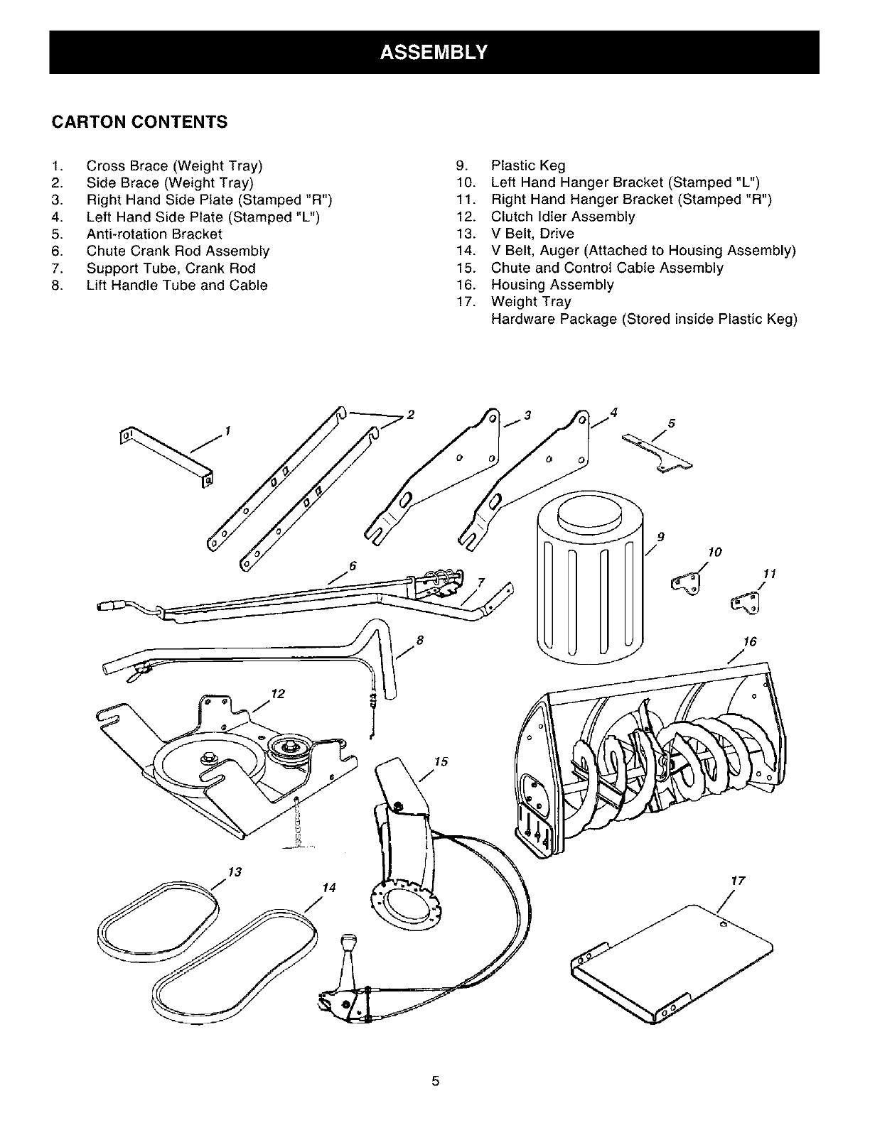
CARTON CONTENTS
1. Cross Brace (Weight Tray)
2. Side Brace (Weight Tray)
3. Right Hand Side Plate (Stamped "R")
4. Left Hand Side Plate (Stamped "L")
5. Anti-rotation Bracket
6. Chute Crank Rod Assembly
7. Support Tube, Crank Rod
8. Lift Handle Tube and Cable
9. Plastic Keg
10. Left Hand Hanger Bracket (Stamped "L")
11. Right Hand Hanger Bracket (Stamped "R")
12. Clutch Idler Assembly
13. V Belt, Drive
14. V Belt, Auger (Attached to Housing Assembly)
15. Chute and Control Cable Assembly
16. Housing Assembly
17. Weight Tray
Hardware Package (Stored inside Plastic Keg)
5
6
12
9
/ 10
5
TOOLS REQUIRED FOR ASSEMBLY
INSTALLING SIDE PLATES ON TRACTOR
(2) 7/16" Wrenches
(2) 1/2" Wrenches
(2) 9/16" Wrenches
(2) 3/4" Wrenches
(1) Knife
ADDITIONAL ITEMS REQUIRED
General Purpose Grease
REMOVAL OF PARTS FROM CARTON
• Remove all parts and hardware packages from the
carton. Lay out parts and hardware and identify using
the illustrations on pages 4 and 5.
NOTE: Not all of the supplied parts and hardware
will be needed for your particular tractor. Unneeded
items may be discarded after you have completed
assembly.
CAUTION: Before starting to assemble
the snow thrower, remove the spark plug
wire(s), set the parking brake and
remove the key from the tractor ignition.
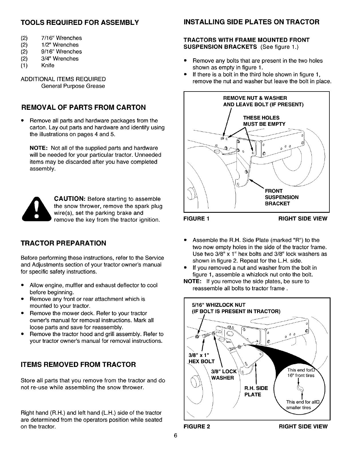
TRACTORS WITH FRAME MOUNTED FRONT
SUSPENSION BRACKETS (See figure 1.)
• Remove any bolts that are present in the two holes
shown as empty in figure 1.
• If there is a bolt in the third hole shown in figure 1,
remove the nut and washer but leave the bolt in place.
REMOVE NUT & WASHER
AND LEAVE BOLT (IF PRESENT)
THESE HOLES
MUST BE EMPTY
FIGURE 1
FRONT
SUSPENSION
BRACKET
RIGHT SIDE VIEW
TRACTOR PREPARATION
Before performing these instructions, refer to the Service
and Adjustments section of your tractor owner's manual
for specific safety instructions.
• Allow engine, muffler and exhaust deflector to cool
before beginning.
• Remove any front or rear attachment which is
mounted to your tractor.
• Remove the mower deck. Refer to your tractor
owner's manual for removal instructions. Mark all
loose parts and save for reassembly.
• Remove the tractor hood and grill assembly. Refer to
your tractor owner's manual for removal instructions.
ITEMS REMOVED FROM TRACTOR
Store all parts that you remove from the tractor and do
not re-use while assembling the snow thrower.
Right hand (R.H.) and left hand (L.H.) side of the tractor
are determined from the operators position while seated
on the tractor.
• Assemble the R.H. Side Plate (marked "R") to the
two now empty holes in the side of the tractor frame.
Use two 3/8" x 1" hex bolts and 3/8" lock washers as
shown in figure 2. Repeat for the L.H. side.
• If you removed a nut and washer from the bolt in
figure 1, assemble a whizlock nut onto the bolt.
NOTE: If you remove the side plates, be sure to
reassemble all bolts to tractor frame.
5/16" WHIZLOCK NUT
(IF BOLT IS PRESENT INTRACTOR)
6
J
FIGURE 2
3/8" LOCI<
WASHER
/
/
R.H. SIDE
PLATE
smaller tires
RIGHT SIDE VIEW

Assemble a shoulder bolt, a 3/8" lock washer and a
3/8" hex lock nut to the bottom hole in each side
plate. See figure 3.
Proceed to page 8.
J
FIGURE 3 RIGHT SIDE VIEW
• Attach the R.H. Side Plate (marked "R") to the right
side of the tractor frame as shown in figure 5. For the
front hole use a 3/8" x 1" hex bolt, a 3/8" lock washer,
and a 1/2" flat washer. Use the flat washer as a shim
between the frame and the side plate. For the rear
hole use a 3/8" x 1" hex bolt, and a 3/8" lock washer.
Repeat for the L.H. side.
NOTE: If the bolt inserts freely into the front hole, the
3/8" lock washer along with a 3/8" hex lock nut must
be assembled onto the bolt from inside the tractor
frame.
3/8" LOCK 1/2" FLAT
WASHER WASHER
[]
3/8" x 1"
HEX BOLT
R.H. SIDE
PLATE
TRACTORS WITH AXLE MOUNTED FRONT
SUSPENSION BRACKETS
• Remove any bolts present in the holes shown in
figure 4 on both sides of the tractor frame.
FIGURE 5 RIGHT SIDE VIEW
• Assemble a shoulder bolt, a 3/8" lock washer and a
3/8" hex lock nut to the bottom hole in each side
plate. See figure 6.
THESE HOLES
MUST BE EMPTY
\
\\ \ \\
FRONT
SUSPENSION
BRACKET
FIGURE 4 RIGHT SIDE VIEW
3_"HEX LOCK NUT
3/_ LOCK
W_SHER
3/8" SHOULDER BOLT
FIGURE 6 RIGHT SIDE VIEW
7
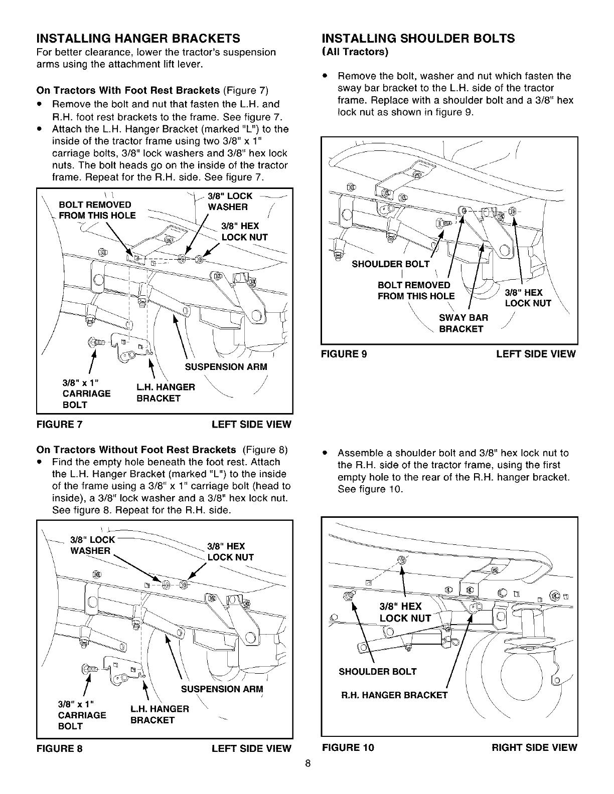
INSTALLING HANGER BRACKETS
For better clearance, lower the tractor's suspension
arms using the attachment lift lever.
On Tractors With Foot Rest Brackets (Figure 7)
• Remove the bolt and nut that fasten the L.H. and
R.H. foot rest brackets to the frame. See figure 7.
• Attach the L.H. Hanger Bracket (marked "L") to the
inside of the tractor frame using two 3/8" x 1"
carriage bolts, 3/8" lock washers and 3/8" hex lock
nuts. The bolt heads go on the inside of the tractor
frame. Repeat for the R.H. side. See figure 7.
/ / / 318"LOCK
BOLTREMOVED WASHER
FROMTHIS HOLE
3/8" HEX
LOCKNUT
t
3/8" x 1"
CARRIAGE
BOLT
SUSPENSION ARM
\ \
LH. HANGER
BRACKET
FIGURE 7 LEFT SIDE VIEW
INSTALLING SHOULDER BOLTS
(All Tractors)
Remove the bolt, washer and nut which fasten the
sway bar bracket to the L.H. side of the tractor
frame. Replace with a shoulder bolt and a 3/8" hex
lock nut as shown in figure 9.
SHOULDER BOLT
I \
BOLT REMOVED
FROM THIS HOLE 3/8" HEX
\ LOCK NUT
\
\
\\ SWAY BAR
\_ BRACKET
FIGURE 9 LEFT SIDE VIEW
On Tractors Without Foot Rest Brackets (Figure 8)
• Find the empty hole beneath the foot rest. Attach
the L.H. Hanger Bracket (marked "L") to the inside
of the frame using a 3/8" x 1" carriage bolt (head to
inside), a 3/8" lock washer and a 3/8" hex lock nut.
See figure 8. Repeat for the R.H. side.
3/8" LOCK
WASHER
_LOCKNUT
SUSPENSION ARM
\
\ \
8_"x1" L.H. HANGER \
CARRIAGE BRACKET
BOLT
Assemble a shoulder bolt and 3/8" hex lock nut to
the R.H. side of the tractor frame, using the first
empty hole to the rear of the R.H. hanger bracket.
See figure 10.
SHOULDER BOLT
R.H. HANGER BRACKET
RIGHT SIDE VIEW
FIGURE 8 LEFT SIDE VIEW FIGURE 10
8

INSTALLING CLUTCH/IDLER ASSEMBLY
• Turn the clutch/idler assembly upside down and
place the extra tensioning chain through the hole
shown in figure 11.
USE THIS HOLE
FIGURE 11
• Hook the loose spring through the end of the
tensioning chain. See figure 12.
• Hook the other end of the spring onto the bottom of
the bolt and nut which secure the idler pulley to the
upper idler arm. Hold the bolt head and assemble a
3/8" hex lock nut onto the bolt, leaving it loose
enough for the spring to pivot freely between the
two nuts. See figure 12.
• Attach a 3/32" hairpin cotter to the chain, placing it
in the fifth link from the spring. See figure 12.
SPRING
5TH LINK
CHAIN
(L.H. SIDE)
3/8" HEX
LOCK NUT
3/32" HAIR
COTTER PIN
RIGHT LEFT
SIDE SIDE
FIGURE 12 VIEW OF BOTTOM
Attach the clutch/idler assembly to the tractor frame
as follows. Hook the assembly's notched arms onto
the two shoulder bolts you assembled to the inside
of the tractor frame. Lift the front of the assembly
and attach it to the R.H. and L.H. hanger brackets
using two pivot lock pins and 1/8" hairpin cotters.
See figure 13.
1/8 COTTER
PIVOT LOCK PIN
(use second hole)
FIGURE 13 RIGHT SIDE VIEW
Assemble the short "V" belt onto the engine pulley
and then onto the large pulley on the clutch/idler
assembly. The belt must be placed to the inside of
the idler pulley and the keeper bolt. See figure 14.
IMPORTANT: Do Not assemble the "V" belt
around the outside of the keeper bolt.
Place tension on the belt by pulling the left side
tensioning chain out as far as the 3/32" hairpin
cotter will allow. Secure the chain with a 1/8"
hairpin cotter. See figure 14.
Hold this drawing above you while viewing the
Clutch/Idler Assembly from underneath the
tractor. Right and left in the drawing will be the
reverse of the viewer's right and left.
3/32" HAIRPIN
COTTER
1/8" HAIRPIN
COTTER
!
IDLER
9
© "_ _'_""" KEEPER
BOLT
- _ Left Side
I °fTract°r
FIGURE 14 VIEWED FROM UNDERNEATH
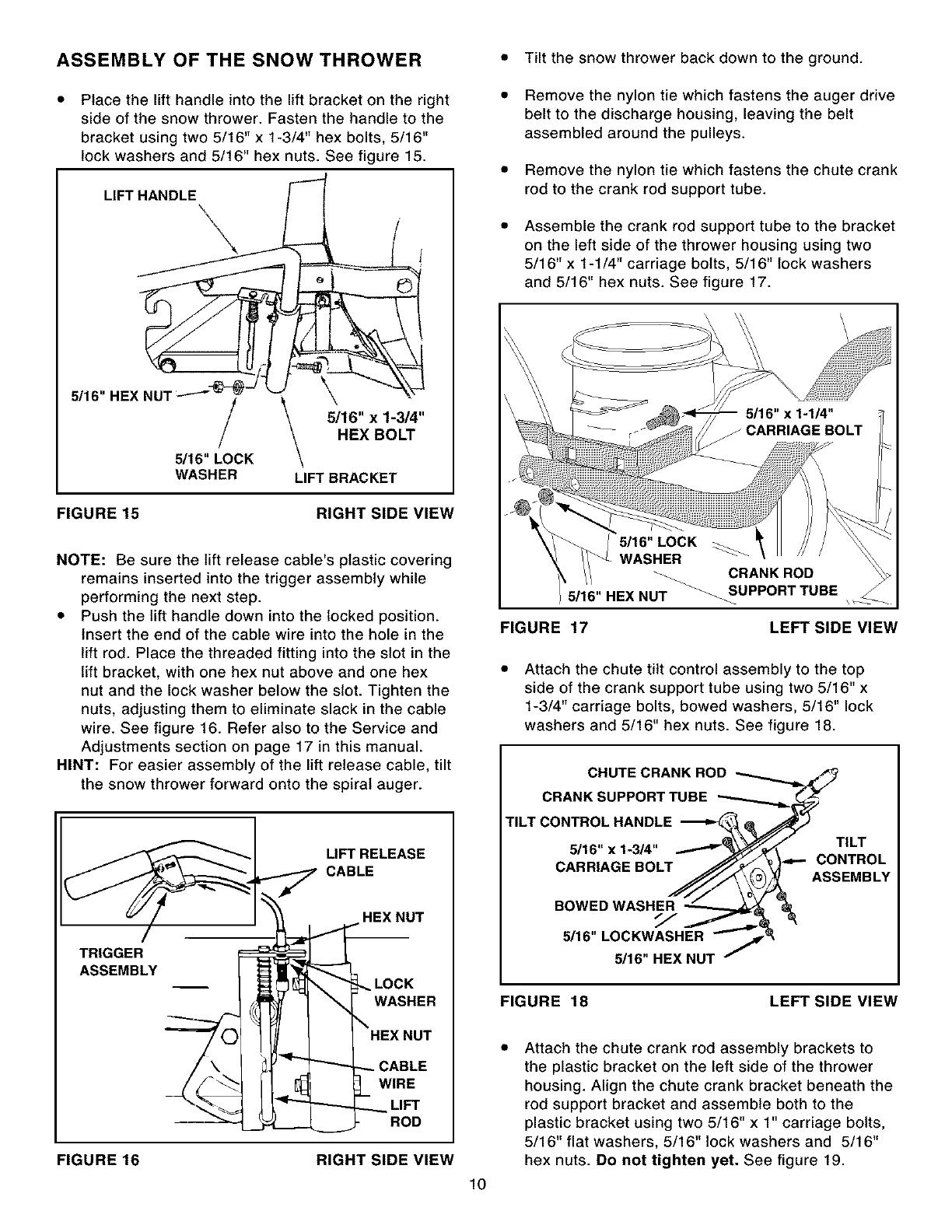
ASSEMBLY OF THE SNOW THROWER • Tilt the snow thrower back down to the ground.
Place the lift handle into the lift bracket on the right
side of the snow thrower. Fasten the handle to the
bracket using two 5/16" x 1-3/4" hex bolts, 5/16"
lock washers and 5/16" hex nuts. See figure 15.
LIFT HANDLE _.
/
5116" LOCK
WASHER
l
5/16" x 1-3/4"
HEX BOLT
LIFT BRACKET
FIGURE 15 RIGHT SIDE VIEW
NOTE: Be sure the lift release cable's plastic covering
remains inserted into the trigger assembly while
performing the next step.
• Push the lift handle down into the locked position.
Insert the end of the cable wire into the hole in the
lift rod. Place the threaded fitting into the slot in the
lift bracket, with one hex nut above and one hex
nut and the lock washer below the slot. Tighten the
nuts, adjusting them to eliminate slack in the cable
wire. See figure 16. Refer also to the Service and
Adjustments section on page 17 in this manual.
HINT: For easier assembly of the lift release cable, tilt
the snow thrower forward onto the spiral auger.
LIFT RELEASE
CABLE
TRIGGER
ASSEMBLY
FIGURE 16
HEX NUT
LOCK
WASHER
HEX NUT
;ABLE
WIRE
LIFT
ROD
RIGHT SIDE VIEW
Remove the nylon tie which fastens the auger drive
belt to the discharge housing, leaving the belt
assembled around the pulleys.
Remove the nylon tie which fastens the chute crank
rod to the crank rod support tube.
Assemble the crank rod support tube to the bracket
on the left side of the thrower housing using two
5/16" x 1-1/4" carriage bolts, 5/16" lock washers
and 5/16" hex nuts. See figure 17.
\ \
5/16" HEX NUT
FIGURE 17
CRANK ROD
_UPPORT TUBE
LEFT SIDE VIEW
Attach the chute tilt control assembly to the top
side of the crank support tube using two 5/16" x
1-3/4" carriage bolts, bowed washers, 5/16" lock
washers and 5/16" hex nuts. See figure 18.
CHUTE CRANK ROD
CRANK SUPPORT TUBE
TILT CONTROL HANDLE
5/16" x 1-3/4"
CARRIAGE BOLT
BOWED WASHER
5/16" LOCKWASHER
_16"HEX NUT
TILT
CONTROL
ASSEMBLY
FIGURE 18 LEFT SIDE VIEW
lO
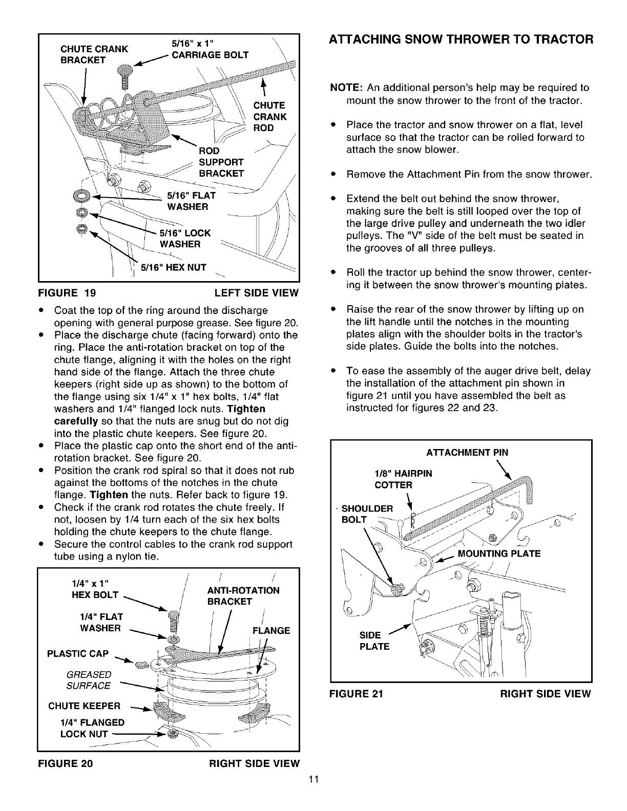
Attach the chute crank rod assembly brackets to
the plastic bracket on the left side of the thrower
housing. Align the chute crank bracket beneath the
rod support bracket and assemble both to the
plastic bracket using two 5/16" x 1" carriage bolts,
5/1 6" flat washers, 5/1 6" lock washers and 5/1 6"
hex nuts. Do not tighten yet. See figure 19.
CHUTE CRANK
BRACKET
5/16" x 1"
.,dw,,,.,,,,._CARRIAGEBOLT
\\
\
FIGURE 19
CHUTE
CRANK
ROD
ROD
SUPPORT J
BRACKET /
_16"FLAT
WASHER
5/16"LOCK _
WASHER
"5/16"HEX NUT
LEFT SIDE VIEW
Coat the top of the ring around the discharge
opening with general purpose grease. See figure 20.
• Place the discharge chute (facing forward) onto the
ring. Place the anti-rotation bracket on top of the
chute flange, aligning it with the holes on the right
hand side of the flange. Attach the three chute
keepers (right side up as shown) to the bottom of
the flange using six 1/4" x 1" hex bolts, 1/4" flat
washers and 1/4" flanged lock nuts. Tighten
carefully so that the nuts are snug but do not dig
into the plastic chute keepers. See figure 20.
• Place the plastic cap onto the short end of the anti-
rotation bracket. See figure 20.
• Position the crank rod spiral so that it does not rub
against the bottoms of the notches in the chute
flange. Tighten the nuts. Refer back to figure 19.
• Check if the crank rod rotates the chute freely. If
not, loosen by 1/4 turn each of the six hex bolts
holding the chute keepers to the chute flange.
• Secure the control cables to the crank rod support
tube using a nylon tie.
1/4" x 1"
I_"FLAT
WASHER
ANTI-ROTATION
BRACKET
FLANGE
PLASTIC CAP
GREASED
SURFACE
CHUTE KEEPER
1/4" FLANGED
LOCK Nu'r
FIGURE 20 RIGHT SIDE VIEW
ATTACHING SNOW THROWER TO TRACTOR
NOTE: An additional person's help may be required to
mount the snow thrower to the front of the tractor.
• Place the tractor and snow thrower on a flat, level
surface so that the tractor can be rolled forward to
attach the snow blower.
• Remove the Attachment Pin from the snow thrower.
Extend the belt out behind the snow thrower,
making sure the belt is still looped over the top of
the large drive pulley and underneath the two idler
pulleys. The "V" side of the belt must be seated in
the grooves of all three pulleys.
• Roll the tractor up behind the snow thrower, center-
ing it between the snow thrower's mounting plates.
Raise the rear of the snow thrower by lifting up on
the lift handle until the notches in the mounting
plates align with the shoulder bolts in the tractor's
side plates. Guide the bolts into the notches.
To ease the assembly of the auger drive belt, delay
the installation of the attachment pin shown in
figure 21 until you have assembled the belt as
instructed for figures 22 and 23.
ATTACHMENTPIN
1/8"HAIRPIN
COTTER
SHOULDER _
BOLT
MOUNTING PLATE
SIDE
PLATE
FIGURE 21 RIGHT SIDE VIEW
11
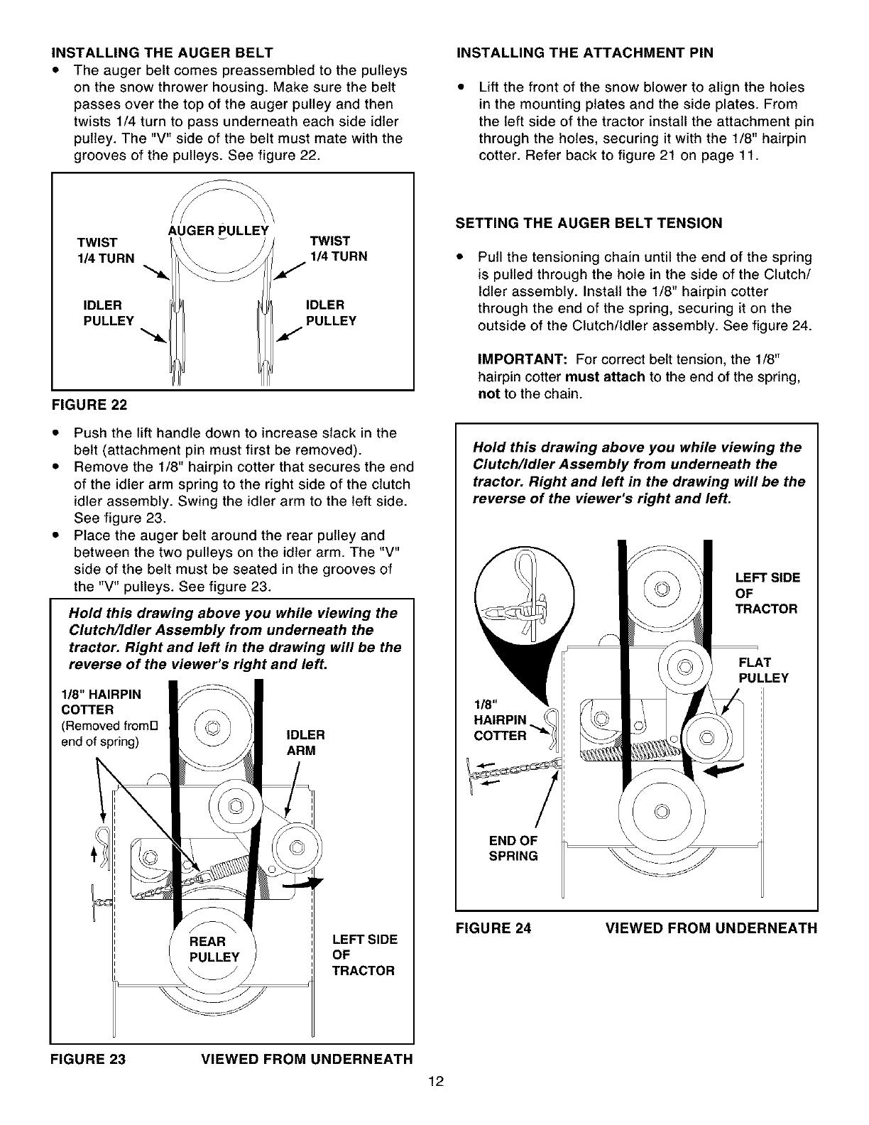
INSTALLINGTHE AUGER BELT
• The auger belt comes preassembled to the pulleys
on the snow thrower housing. Make sure the belt
passes over the top of the auger pulley and then
twists 1/4 turn to pass underneath each side idler
pulley. The "V" side of the belt must mate with the
grooves of the pulleys. See figure 22.
INSTALLING THE ATTACHMENT PIN
Lift the front of the snow blower to align the holes
in the mounting plates and the side plates. From
the left side of the tractor install the attachment pin
through the holes, securing it with the 1/8" hairpin
cotter. Refer back to figure 21 on page 11.
TWIST
1/4 TURN
IDLER
PULLEY
AUGER PULLEY
TWIST
1_ TURN
IDLER
PULLEY
FIGURE 22
• Push the lift handle down to increase slack in the
belt (attachment pin must first be removed).
• Remove the 1/8" hairpin cotter that secures the end
of the idler arm spring to the right side of the clutch
idler assembly. Swing the idler arm to the left side.
See figure 23.
• Place the auger belt around the rear pulley and
between the two pulleys on the idler arm. The "V"
side of the belt must be seated in the grooves of
the "V" pulleys. See figure 23.
Hold this drawing above you while viewing the
Clutch/Idler Assembly from underneath the
tractor. Right and left in the drawing will be the
reverse of the viewer's right and left.
1/8" HAIRPIN
COTTER
(Removed fromFI
end of spring)
IDLER
ARM
REAR
PULLEY
LEFT SIDE
OF
TRACTOR
SETTING THE AUGER BELT TENSION
Pull the tensioning chain until the end of the spring
is pulled through the hole in the side of the Clutch/
Idler assembly. Install the 1/8" hairpin cotter
through the end of the spring, securing it on the
outside of the Clutch/Idler assembly. See figure 24.
IMPORTANT: For correct belt tension, the 1/8"
hairpin cotter must attach to the end of the spring,
not to the chain.
Hold this drawing above you while viewing the
Clutch/Idler Assembly from underneath the
tractor. Right and left in the drawing will be the
reverse of the viewer's right and left.
LEFT SIDE
OF
TRACTOR
FLAT
PULLEY
FIGURE 24 VIEWED FROM UNDERNEATH
FIGURE 23 VIEWED FROM UNDERNEATH
12
ATTACHING WEIGHT TRAY TO TRACTOR
Loosen the top hex bolt on each side of the tractor
frame at the rear. Assemble the slotted end of the
side braces down onto the loosened bolts. Do not
tighten yet. See figure 25.
Place the weight tray on top of the tractor hitch and
fasten the side braces to it using two 5/16" x 1"
carriage bolts, 5/16" lock washers and 5/16" hex
nuts. Do not tighten yet. See figure 25.
• Fasten the weight tray to the tractor hitch using a
1/2" x 1-1/4" hex bolt, a 1/2" lock washer and a 1/2"
hex nut. Do not tighten yet. See figure 25.
Fasten the cross brace to the side braces using
two 5/16" x 1" carriage bolts, 5/16" lock washers
and 5/16" hex nuts. See figure 25. Tighten all
loose bolts at this time.
NOTE: Tire chains on extra wide tires may rub the hex
bolt. See the alternate instructions on this page.
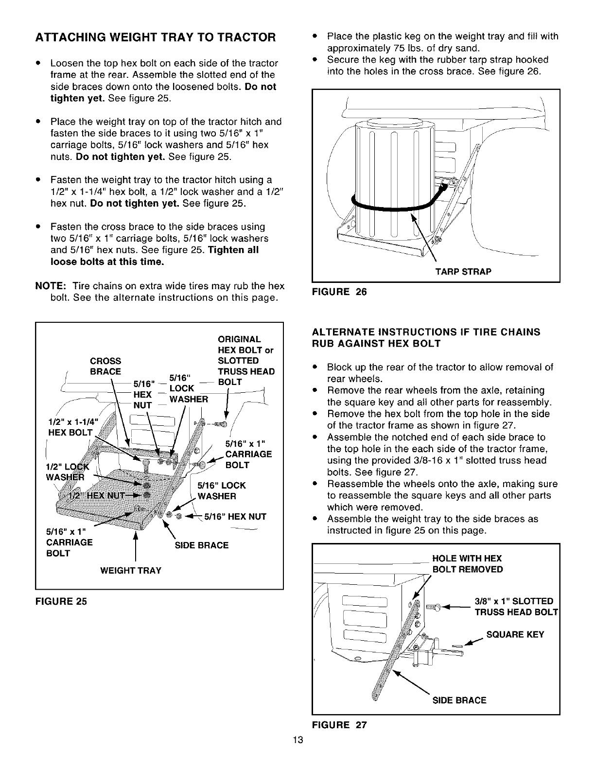
• Place the plastic keg on the weight tray and fill with
approximately 75 lbs. of dry sand.
• Secure the keg with the rubber tarp strap hooked
into the holes in the cross brace. See figure 26.
q
TARPSTRAP
FIGURE 26
ORIGINAL
HEX BOLT or
CROSS SLOTTED
BRACE TRUSS HEAD
5/16" --BOLT
LOCK
WASHER
/
1_"x1-1_"
HEXBOLT
_16"x 1"
CARRIAGE
BOLT
WEIGHT TRAY
5/16" x 1"
CARRIAGE
BOLT
5/16" LOCK
WASHER
5/16"HEX NUT
SIDE BRACE
ALTERNATE INSTRUCTIONS IF TIRE CHAINS
RUB AGAINST HEX BOLT
• Block up the rear of the tractor to allow removal of
rear wheels.
• Remove the rear wheels from the axle, retaining
the square key and all other parts for reassembty.
• Remove the hex bolt from the top hole in the side
of the tractor frame as shown in figure 27.
• Assemble the notched end of each side brace to
the top hole in the each side of the tractor frame,
using the provided 3/8-16 x 1" slotted truss head
bolts. See figure 27.
• Reassemble the wheels onto the axle, making sure
to reassemble the square keys and all other parts
which were removed.
• Assemble the weight tray to the side braces as
instructed in figure 25 on this page.
HOLE WITH HEX
BOLT REMOVED
FIGURE 25 3/8" x 1" SLOTTED
TRUSS HEAD BOLT
SQUARE KEY
SIDE BRACE
FIGURE 27
13

Ifyourtractorisnotequippedwithrearreflectors,
assemblethetailreflectorstotherearfender.
Placethereflectorsasclosetothebottomofthe
fenderandasfarapartastheshapeofthefender
willallow.Seefigure28.
\
TAIL REFLECTORS
FIGURE 28
CHECKLIST
Before you operate your snow thrower, please
review the following checklist to help ensure that
you will obtain the best performance from your
snow thrower.
• All assembly instructions have been completed with
all bolts and nuts properly tightened.
• Check the engine belt and the auger belt. Make
sure they are routed properly around pulleys and
inside all belt keepers.
• Check discharge chute for proper rotation.
• Check operation of tilt control for upper chute.
• Verify that the lift handle will lock into and release
from the raised transport position. (Refer to the
Service and Adjustments section.)
• Check skid shoe adjustment. (Refer to the Service
and Adjustments section.)
The following additional items are available from
Sears to help enhance the performance of your
snow thrower. See page 2.
• Tire chains which can be installed to improve
traction.
• Rear wheel weights which can be installed in
addition to the rear weight tray to improve traction.
• Drift cutter bars which can be installed to help slice
off the edges of tall drifts.
14
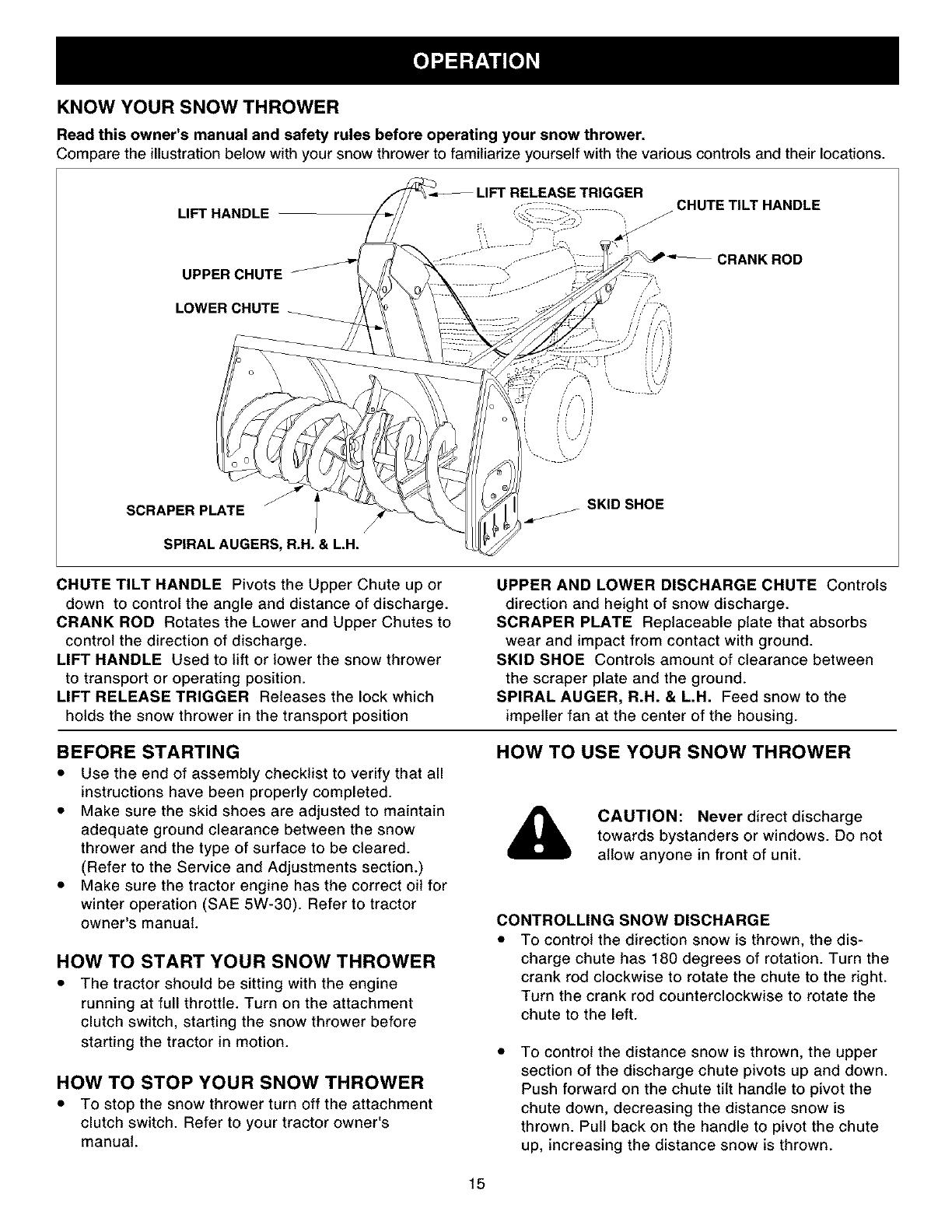
KNOW YOUR SNOW THROWER
Read this owner's manual and safety rules before operating our snow thrower.
Compare the illustration below with your snow thrower to familiarize yourself with the various controls and their locations.
LIFT HANDLE
_ETRIGGER
CHUTE TILT HANDLE
UPPER CHUTE
CRANK ROD
LOWER CHUTE
SCRAPER PLATE
SPIRAL AUGERS, R.H.& L.H.
SKID SHOE
CHUTE TILT HANDLE Pivots the Upper Chute up or
down to control the angle and distance of discharge.
CRANK ROD Rotates the Lower and Upper Chutes to
control the direction of discharge.
LIFT HANDLE Used to lift or lower the snow thrower
to transport or operating position.
LIFT RELEASE TRIGGER Releases the lock which
holds the snow thrower in the transport position
BEFORE STARTING
• Use the end of assembly checklist to verify that all
instructions have been properly completed.
• Make sure the skid shoes are adjusted to maintain
adequate ground clearance between the snow
thrower and the type of surface to be cleared.
(Refer to the Service and Adjustments section.)
• Make sure the tractor engine has the correct oil for
winter operation (SAE 5W-30). Refer to tractor
owner's manual.
UPPER AND LOWER DISCHARGE CHUTE Controls
direction and height of snow discharge.
SCRAPER PLATE Replaceable plate that absorbs
wear and impact from contact with ground.
SKID SHOE Controls amount of clearance between
the scraper plate and the ground.
SPIRAL AUGER, R.H. & L.H. Feed snow to the
impeller fan at the center of the housing.
HOW TO USE YOUR SNOW THROWER
CAUTION: Never direct discharge
towards bystanders or windows. Do not
allow anyone in front of unit.
CONTROLLING SNOW DISCHARGE
HOW TO START YOUR SNOW THROWER
• The tractor should be sitting with the engine
running at full throttle. Turn on the attachment
clutch switch, starting the snow thrower before
starting the tractor in motion.
HOW TO STOP YOUR SNOW THROWER
• To stop the snow thrower turn off the attachment
clutch switch. Refer to your tractor owner's
manual.
To control the direction snow is thrown, the dis-
charge chute has 180 degrees of rotation. Turn the
crank rod clockwise to rotate the chute to the right.
Turn the crank rod counterclockwise to rotate the
chute to the left.
To control the distance snow is thrown, the upper
section of the discharge chute pivots up and down.
Push forward on the chute tilt handle to pivot the
chute down, decreasing the distance snow is
thrown. Pull back on the handle to pivot the chute
up, increasing the distance snow is thrown.
15

RAISING AND LOWERING
• To raise, push down on the lift handle until the
snow thrower locks in the raised transport position.
• To lower, push down slightly on the lift handle and
pull the trigger. With the trigger pulled, slowly lower
the snow thrower until it reaches the ground.
CAUTION: Do not operate the snow
thrower without the rear weight attached
to the tractor to provide extra traction
and stability.
REMOVING SNOW
Snow removal conditions vary greatly from light fluffy
snowfall to wet heavy snow. Operating instructions
must be flexible to fit the conditions encountered. The
operator must adapt the lawn tractor and snow thrower
to depth of snow, wind direction, temperature and
surface conditions.
• Before beginning operation, thoroughly inspect the
area of operation and remove all door mats, sleds,
boards, wires and other foreign objects.
• The spiral auger speed is directly related to engine
speed. For maximum snow removal and discharge,
maintain high engine r.p.m. (full throttle). It is
advisable to operate the lawn tractor at a slow
ground speed (1st gear) for safe and efficient snow
removal.
• In deep, drifted or banked snow it will be necessary
to use full throttle and a slow ground speed (1st
gear). Drive forward into the snow, depress the
tractor's clutch-brake pedal and allow the spiral
auger to clear the snow. Repeat this method until a
path is cleared. On the second pass, overlap the
first enough to allow the snow thrower to handle
the snow without repeated stopping and starting of
forward motion.
• In extremely deep snow, raise the snow thrower
from the ground to remove the top layer and drive
forward only until the tractors front tires reach the
uncleared bottom layer of snow. Depress the
tractor's clutch-brake pedal and allow the spiral
auger to clear the snow. Reverse the tractor and
lower the snow thrower to the ground. Drive the
tractor forward until the snow again becomes too
deep. Repeating this process into and out of drifts
will eventually clear even the deepest of snow
piles.
• If the snow thrower becomes clogged with snow or
jammed with a foreign object, disengage the snow
thrower immediately and shut off the tractor engine.
Unclog the snow thrower before resuming opera-
tion.
DANGER: Shut off engine and
disengage snow thrower before
unclogging discharge chute. Unclog
using a wooden stick, not your hands.
OPERATING TIPS
• Discharge snow down wind whenever possible.
• To help prevent snow from sticking to the snow
thrower, allow the snow thrower to reach outdoor
temperature before using it. A light coat of wax may
also be applied to the inside surface of the snow
thrower housing and discharge chute.
• Use tire chains to improve traction.
• Use rear wheel weights to improve traction.
• Before the first snowfall, remove all stones, sticks
and other objects which could become hidden by
the snow. Permanent obstacles should be marked
for visibility.
• Overlap each pass slightly to assure complete
snow removal.
CUSTOMER RESPONSIBILITIES
• Read and follow the maintenance schedule and the maintenance procedures listed in this section.
Fill in dates as you
complete regular service. /_° _Z_ 7
Checkfor loosefasteners X
Checkscraper and shoes forwear X X
Cleaning X
LubricationSection X
Service Dates
LUBRICATION
• Oil all pivot points on the snow thrower.
• Oil the pivot points of the two idler arms on the
clutch/idler assembly.
• Apply penetrating oil to the control cables of the
discharge chute.
• Apply a good grade of spray lubricant to the trigger
assembly and the chute tilt control assembly.
16
CHECK SCRAPER AND SHOES FOR WEAR
(Refer to figures 29 and 30 on page 17.)
• The scraper plate and skid shoes on the bottom of
the snow thrower are subject to wear. To prevent
damage to the spiral auger housing, replace plate
and shoes before wear is excessive.
&
CAUTION: Before servicing or adjusting
the snow thrower, shut off the engine,
remove the spark plug wire(s), set the
parking brake and remove the key from
the tractor ignition.
REPLACING AUGER BELT
• Release spring tension from the upper drive belt.
• Lower the snow thrower to the ground.
• Remove the attachment pin.
• Lock the snow thrower's lift handle in the down
position to decrease auger belt tension.
• Release spring tension from the lower auger belt.
• Remove the auger drive belt from the clutch/idler
assembly and from the spiral auger housing.
• Install new belt over top of large auger drive pulley
and under the two side idler pulleys. Twist the belt
1/4 turn to seat the "V" of the belt in the groove of
each idler pulley. Refer to figure 22 on page 12.
Assemble the belt onto the clutch/idler assembly.
Refer to figures 23 and 24 on page 12.
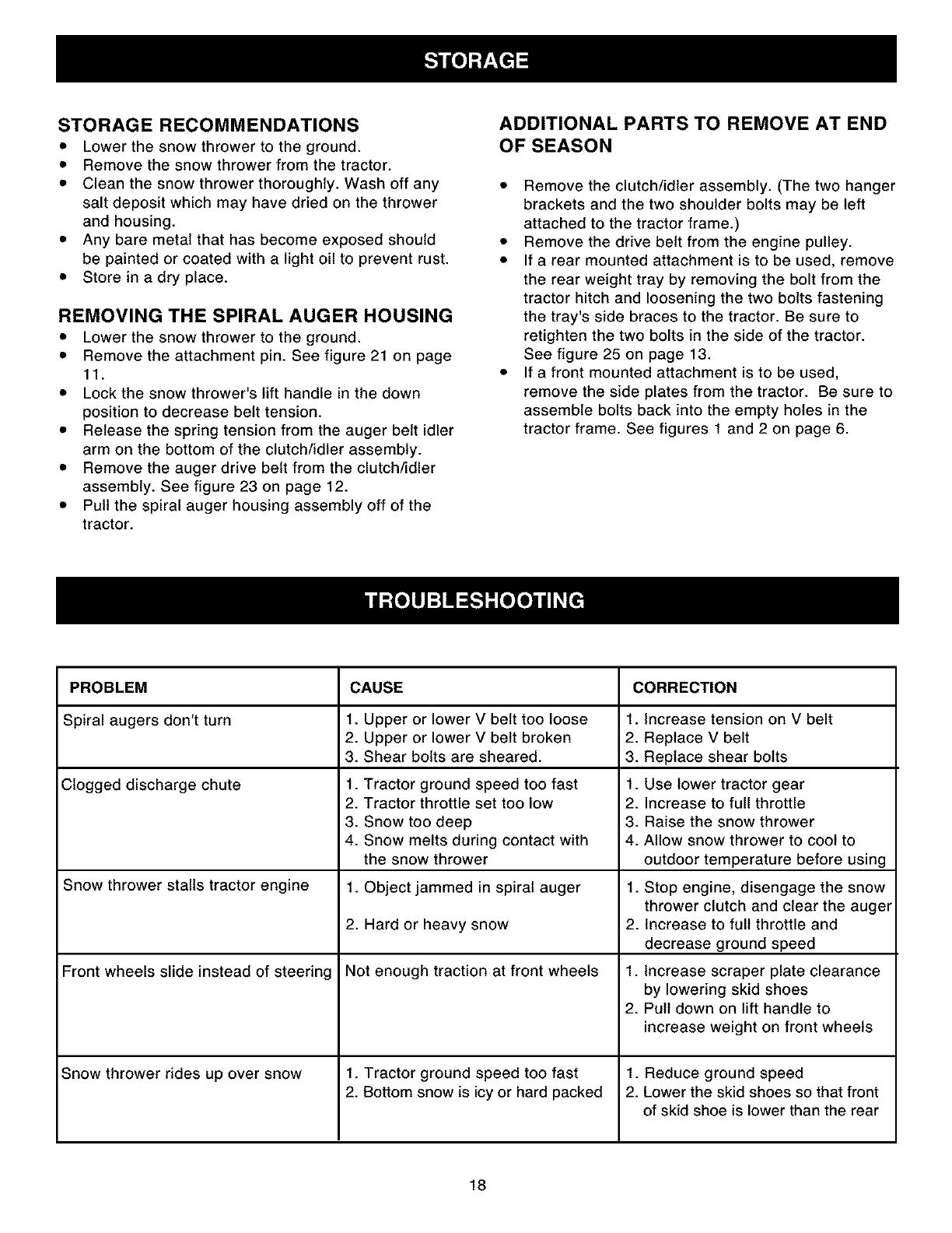
SKID SHOE ADJUSTMENT
• The skid shoes are mounted on each side of the
spiral auger housing. They regulate the distance
the scraper plate is raised above the plowing
surface. When removing snow from a gravel
driveway or and uneven surface, it is advisable to
keep the scraper plate as high above the surface
as possible to prevent possible damage to the
spiral auger. On blacktop or concrete, keep the
scraper plate as close to the surface as possible.
• Raise the snow thrower off the ground and place a
block under each end of the scraper plate. Loosen
the six hex nuts securing the skid shoes to the
housing. Adjust the skid shoes up or down and
retighten the nuts securely. Adjust both skid shoes
to the same height to keep the housing and the
scraper plate level. See figure 29.
LIFT RELEASE CABLE ADJUSTMENT
• If the lift rod does not lock the snow thrower
securely in the transport position, loosen the upper
hex nut on the lift bracket a few turns and tighten
the lower hex nut. Refer to figure 16 on page 10.
• If the lift rod fails to unlock completely to lower the
snow thrower, loosen the lower hex nut on the lift
bracket a few turns and tighten the upper hex nut.
Refer to figure 16 on page 10.
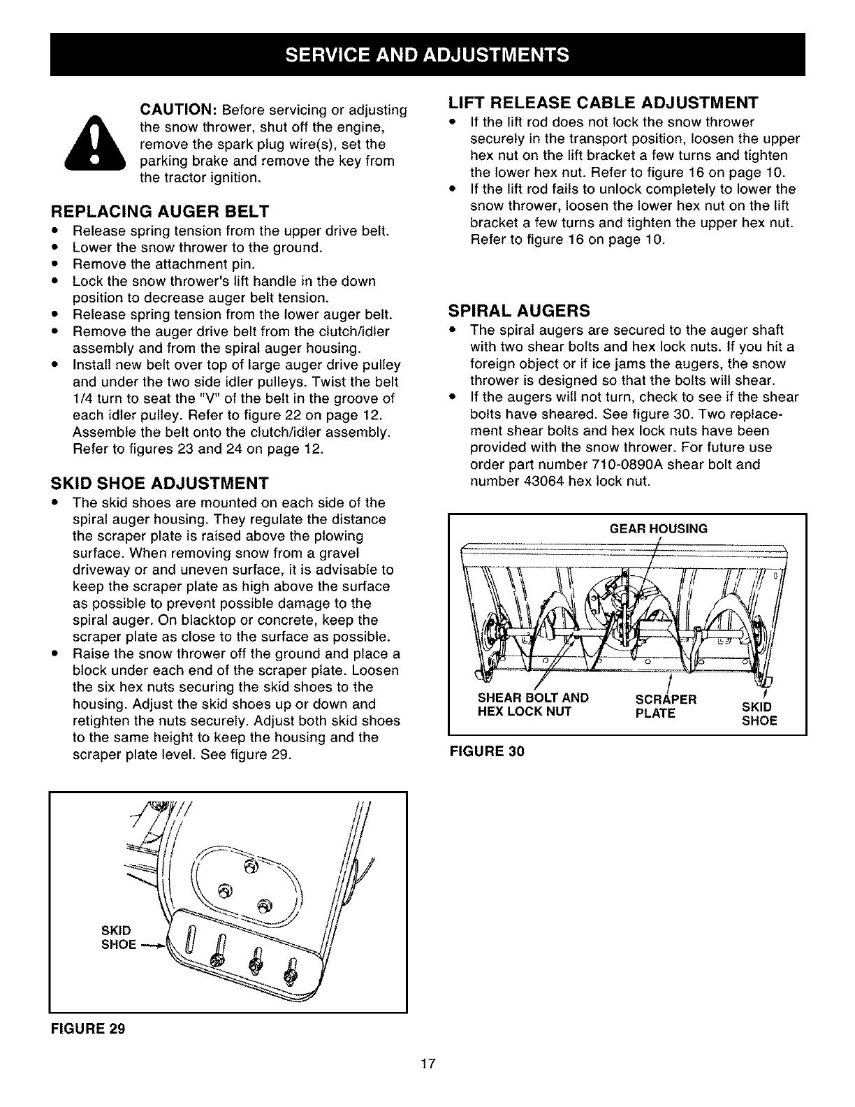
SPIRAL AUGERS
• The spiral augers are secured to the auger shaft
with two shear bolts and hex lock nuts. if you hit a
foreign object or if ice jams the augers, the snow
thrower is designed so that the bolts will shear.
• If the augers will not turn, check to see if the shear
bolts have sheared. See figure 30. Two replace-
ment shear bolts and hex lock nuts have been
provided with the snow thrower. For future use
order part number 710-0890A shear bolt and
number 43064 hex lock nut.
GEAR HOUSING
!
SHEAR BO_ AND SCRAPER
HEXLOCKNUT PLATE SKID
SHOE
FIGURE 30
SKID
SHOE
FIGURE 29
17
STORAGE RECOMMENDATIONS
• Lower the snow thrower to the ground.
• Remove the snow thrower from the tractor.
• Clean the snow thrower thoroughly. Wash off any
salt deposit which may have dried on the thrower
and housing.
• Any bare metal that has become exposed should
be painted or coated with a light oil to prevent rust.
• Store in a dry place.
REMOVING THE SPIRAL AUGER HOUSING
• Lower the snow thrower to the ground.
• Remove the attachment pin. See figure 21 on page
11.
• Lock the snow thrower's lift handle in the down
position to decrease belt tension.
• Release the spring tension from the auger belt idler
arm on the bottom of the clutch/idler assembly.
• Remove the auger drive belt from the clutch/idler
assembly. See figure 23 on page 12.
• Pull the spiral auger housing assembly off of the
tractor.
ADDITIONAL PARTS TO REMOVE AT END
OF SEASON
• Remove the clutch/idler assembly. (The two hanger
brackets and the two shoulder bolts may be left
attached to the tractor frame.)
• Remove the drive belt from the engine pulley.
• If a rear mounted attachment is to be used, remove
the rear weight tray by removing the bolt from the
tractor hitch and loosening the two bolts fastening
the tray's side braces to the tractor. Be sure to
retighten the two bolts in the side of the tractor.
See figure 25 on page 13.
• If a front mounted attachment is to be used,
remove the side plates from the tractor. Be sure to
assemble bolts back into the empty holes in the
tractor frame. See figures 1 and 2 on page 6.
PROBLEM CAUSE CORRECTION
Spiral augers don't turn 1. Upper or lower V belt too loose 1. Increase tension on V belt
2. Upper or lower V belt broken 2. Replace V belt
3. Shear bolts are sheared. 3. Replace shear bolts
Clogged discharge chute 1. Tractor ground speed too fast 1. Use lower tractor gear
2. Tractor throttle set too low 2. Increase to full throttle
3. Snow too deep 3. Raise the snow thrower
4. Snow melts during contact with 4. Allow snow thrower to cool to
the snow thrower outdoor temperature before using
Snow thrower stalls tractor engine 1. Object jammed in spiral auger 1. Stop engine, disengage the snow
thrower clutch and clear the auger
2. Hard or heavy snow 2. Increase to full throttle and
decrease ground speed
Front wheels slide instead of steering Not enough traction at front wheels 1. Increase scraper plate clearance
by lowering skid shoes
2. Pull down on lift handle to
increase weight on front wheels
Snow thrower rides up over snow 1. Tractor ground speed too fast 1. Reduce ground speed
2. Bottom snow is icy or hard packed 2. Lower the skid shoes so that front
of skid shoe is lower than the rear
18

NOTES
19
21
2Z
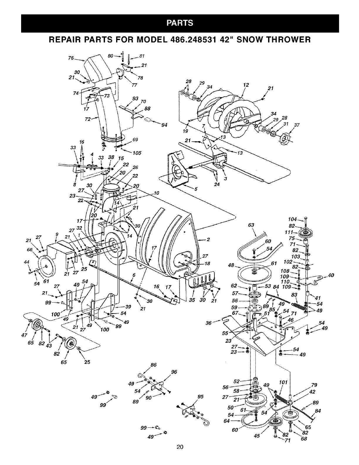
REPAIR PARTS FOR MODEL 486.248531 42" SNOW THROWER
30
21.
9
78
28 29
77 12
16
33
93
70
17 _.88
33 38 15
"105
26
21
/
34
28
94 _I 37
19
I04_
63 82
44
47
65
54 61
27
21
49
82
65
\
21
25
7 _
49
99
86
/ 96
89
35 30 21
55
95
64_
60
49
84
/