Pioneer VSX-819H User manual

Category
AV receivers
Type
User manual

This manual is also suitable for

Register your product at:
www.pioneerelectronics.com (US)
www.pioneerelectronics.ca (Canada)
• Protect your new investment
The details of your purchase will be on file for reference in the event of an
insurance claim such as loss or theft.
• Improve product development
Your input helps us continue to design products that meet your needs.
• Receive a free Pioneer newsletter
Registered customers can opt in to receive a monthly newsletter.
• Receive free tips, updates and service bulletins on
your new product
AUDIO/VIDEO MULTI-CHANNEL RECEIVER
RECEPTEUR AUDIOVISUEL A
VOIES MULTIPLES
RECEPTOR MULTICANAL DE AUDIO/VÍDEO
VSX-819H
Operating Instructions
Mode demploi
Manual de instrucciones
VSX-819H_KU.book Page 1 Thursday, December 25, 2008 8:36 AM
If the AC plug of this unit does not match the AC
outlet you want to use, the plug must be removed
and appropriate one fitted. Replacement and
mounting of an AC plug on the power supply cord of
this unit should be performed only by qualified
service personnel. If connected to an AC outlet, the
cut-off plug can cause severe electrical shock. Make
sure it is properly disposed of after removal.
The equipment should be disconnected by removing
the mains plug from the wall socket when left
unused for a long period of time (for example, when
on vacation).
D3-4-2-2-1a_A_En
IMPORTANT NOTICE THE SERIAL NUMBER FOR THIS EQUIPMENT IS LOCATED IN THE REAR.
PLEASE WRITE THIS SERIAL NUMBER ON YOUR ENCLOSED WARRANTY CARD AND
KEEP IN A SECURE AREA. THIS IS FOR YOUR SECURITY.
D1-4-2-6-1_En
NOTE: This equipment has been tested and found to comply with the limits for a Class B digital device, pursuant to
Part 15 of the FCC Rules. These limits are designed to provide reasonable protection against harmful interference in
a residential installation. This equipment generates, uses, and can radiate radio frequency energy and, if not
installed and used in accordance with the instructions, may cause harmful interference to radio communications.
However, there is no guarantee that interference will not occur in a particular installation. If this equipment does
cause harmful interference to radio or television reception, which can be determined by turning the equipment off
and on, the user is encouraged to try to correct the interference by one or more of the following measures:
– Reorient or relocate the receiving antenna.
– Increase the separation between the equipment and receiver.
– Connect the equipment into an outlet on a circuit different from that to which the receiver is connected.
– Consult the dealer or an experienced radio/TV technician for help.
D8-10-1-2_En
This Class B digital apparatus complies with Canadian ICES-003.
Cet appareil numérique de la Classe B est conforme à la norme NMB-003 du Canada.
D8-10-1-3_EF
Information to User
Alterations or modifications carried out without appropriate authorization may invalidate the user’s right to operate
the equipment.
D8-10-2_En
CAUTION: This product satisfies FCC regulations when shielded cables and connectors are used to connect the
unit to other equipment. To prevent electromagnetic interference with electric appliances such as radios and
televisions, use shielded cables and connectors for connections.
D8-10-3a_En
FEDERAL COMMUNICATIONS COMMISSION DECLARATION OF CONFORMITY
This device complies with part 15 of the FCC Rules. Operation is subject to the following two conditions: (1) This
device may not cause harmful interference, and (2) this device must accept any interference received, including
interference that may cause undesired operation.
Product Name: AUDIO/VIDEO MULTI-CHANNEL RECEIVER
Model Number: VSX-819H-K
Responsible Party Name: PIONEER ELECTRONICS SERVICE, INC.
Address: 1925 E. DOMINGUEZ ST. LONG BEACH, CA 90801-1760, U.S.A.
Phone: 1-800-421-1404
WARNING: Handling the cord on this product or
cords associated with accessories sold with the
product will expose you to chemicals listed on
proposition 65 known to the State of California and
other governmental entities to cause cancer and
birth defect or other reproductive harm.
D36-P4_A_En
Wash hands after handling
WARNING
This equipment is not waterproof. To prevent a fire
or shock hazard, do not place any container filled
with liquid near this equipment (such as a vase or
flower pot) or expose it to dripping, splashing, rain
or moisture.
D3-4-2-1-3_B_En
WARNING
The voltage of the available power supply differs
according to country or region. Be sure that the
power supply voltage of the area where this unit
will be used meets the required voltage (e.g., 230 V
or 120 V) written on the rear panel.
D3-4-2-1-4_A_En
Before plugging in for the first time, read the following
section carefully.
This product is for general household purposes. Any
failure due to use for other than household purposes
(such as long-term use for business purposes in a
restaurant or use in a car or ship) and which
requires repair will be charged for even during the
warranty period.
K041_En
VSX-819H_KU.book Page 2 Thursday, December 25, 2008 8:36 AM
Read these instructions.
Keep these instructions.
Heed all warnings.
Follow all instructions.
Do not use this apparatus near water.
Clean only with dry cloth.
Do not block any ventilation openings. Install in
accordance with the manufacturer’s instructions.
Do not install near any heat sources such as
radiators, heat registers, stoves, or other apparatus
(including amplifiers) that produce heat.
Do not defeat the safety purpose of the polarized or
grounding-type plug. A polarized plug has two
blades with one wider than the other. A grounding
type plug has two blades and a third grounding
prong. The wide blade or the third prong are
provided for your safety. If the provided plug does
not fit into your outlet, consult an electrician for
replacement of the obsolete outlet.
Protect the power cord from being walked on or
pinched particularly at plugs, convenience
receptacles, and the point where they exit from the
apparatus.
1)
2)
3)
4)
5)
6)
7)
8)
9)
10)
Only use attachments/accessories specified by the
manufacturer.
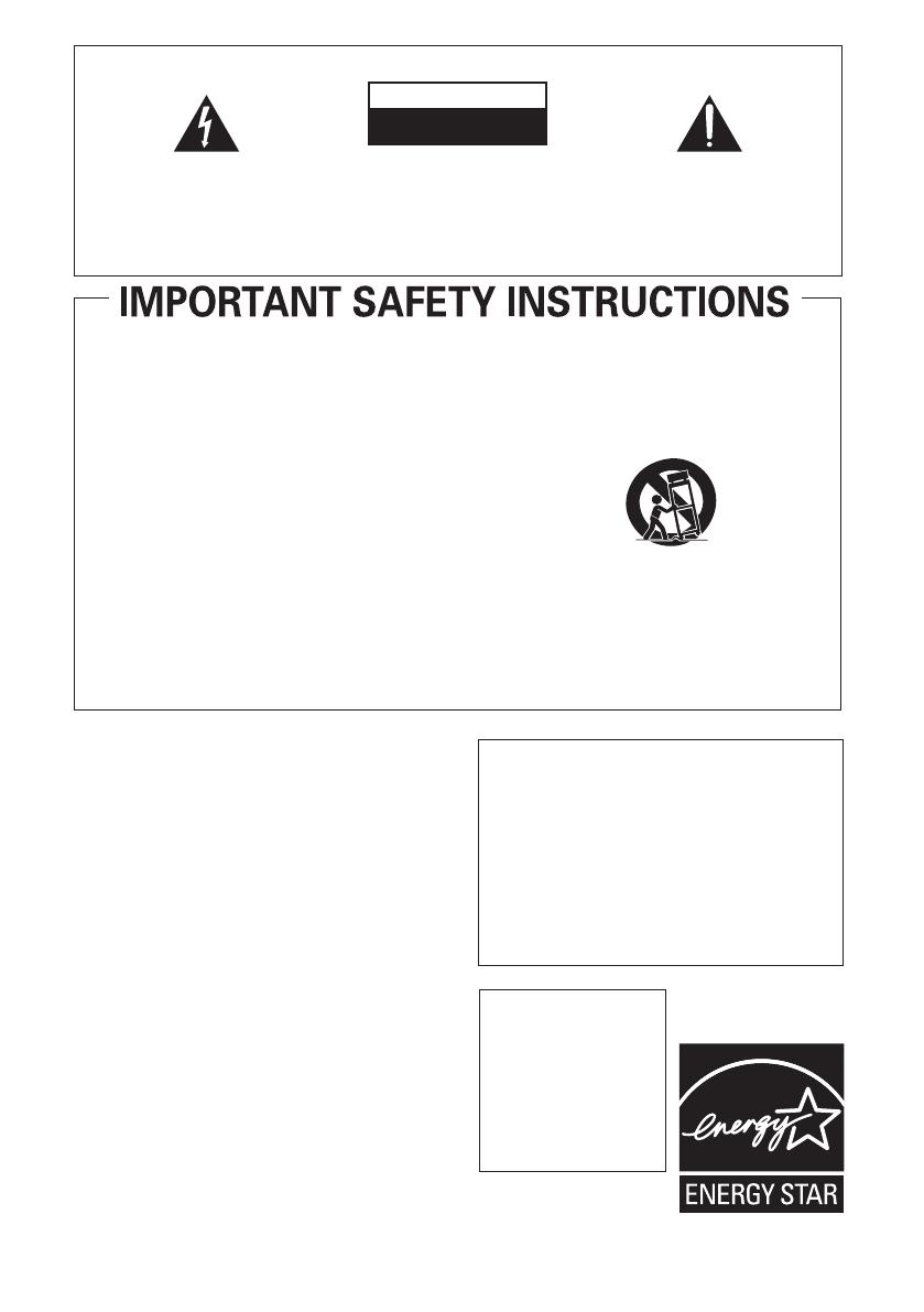
Use only with the cart, stand, tripod, bracket, or
table specified by the manufacturer, or sold with the
apparatus. When a cart is used, use caution when
moving the cart/apparatus combination to avoid
injury from tip-over.
Unplug this apparatus during lightning storms or
when unused for long periods of time.
Refer all servicing to qualified service personnel.
Servicing is required when the apparatus has been
damaged in any way, such as power-supply cord or
plug is damaged, liquid has been spilled or objects
have fallen into the apparatus, the apparatus has
been exposed to rain or moisture, does not operate
normally, or has been dropped.
11)
12)
13)
14)
The exclamation point within an equilateral
triangle is intended to alert the user to the
presence of important operating and
maintenance (servicing) instructions in the
literature accompanying the appliance.
The lightning flash with arrowhead symbol,
within an equilateral triangle, is intended to
alert the user to the presence of uninsulated
"dangerous voltage" within the product's
enclosure that may be of sufficient
magnitude to constitute a risk of electric
shock to persons.
CAUTION:
TO PREVENT THE RISK OF ELECTRIC
SHOCK, DO NOT REMOVE COVER (OR
BACK). NO USER-SERVICEABLE PARTS
INSIDE. REFER SERVICING TO QUALIFIED
SERVICE PERSONNEL.
CAUTION
RISK OF ELECTRIC SHOCK
DO NOT OPEN
IMPORTANT
D3-4-2-1-1_En-A
WARNING
To prevent a fire hazard, do not place any naked
flame sources (such as a lighted candle) on the
equipment.
D3-4-2-1-7a_A_En
VENTILATION CAUTION
When installing this unit, make sure to leave space
around the unit for ventilation to improve heat
radiation (at least 60 cm at top, 10 cm at rear, and
30 cm at each side).
WARNING
Slots and openings in the cabinet are provided for
ventilation to ensure reliable operation of the
product, and to protect it from overheating. To
prevent fire hazard, the openings should never be
blocked or covered with items (such as newspapers,
table-cloths, curtains) or by operating the
equipment on thick carpet or a bed.
D3-4-2-1-7b_A_En
Operating Environment
Operating environment temperature and humidity:
+5 ºC to +35 ºC (+41 ºF to +95 ºF); less than 85 %RH
(cooling vents not blocked)
Do not install this unit in a poorly ventilated area, or in
locations exposed to high humidity or direct sunlight (or
strong artificial light)
D3-4-2-1-7c_A_En
CAUTION
The STANDBY/ON switch on this unit will not
completely shut off all power from the AC outlet.
Since the power cord serves as the main disconnect
device for the unit, you will need to unplug it from
the AC outlet to shut down all power. Therefore,
make sure the unit has been installed so that the
power cord can be easily unplugged from the AC
outlet in case of an accident. To avoid fire hazard,
the power cord should also be unplugged from the
AC outlet when left unused for a long period of time
(for example, when on vacation).
D3-4-2-2-2a_A_En
CAUTION
To prevent fire hazard, the
Class 2 Wiring Cable
should be used for
connection with speaker,
and should be routed
away from hazards to
avoid damage to the
insulation of the cable.
P1-4-2-2_En
For U.S. and Australia Model
VSX-819H_KU.book Page 3 Thursday, December 25, 2008 8:36 AM
4
En
Contents
01 Before you start
Checking what’s in the box . . . . . . . . . . . . . . . 6
Loading the batteries . . . . . . . . . . . . . . . . . . . 6
Installing the receiver . . . . . . . . . . . . . . . . . . . 6
Ventilation . . . . . . . . . . . . . . . . . . . . . . . . . . 6
02 5 minute guide
Introduction to home theater . . . . . . . . . . . . . 8
Listening to Surround Sound . . . . . . . . . . . . . 8
Automatically setting up for surround
sound (MCACC) . . . . . . . . . . . . . . . . . . . . . . . 9
Other problems when using the
Auto MCACC Setup . . . . . . . . . . . . . . . . . . 11
Better sound using Phase Control . . . . . . . . 11
03 Connecting up
Making cable connections . . . . . . . . . . . . . . 12
HDMI cables . . . . . . . . . . . . . . . . . . . . . . . 12
About HDMI . . . . . . . . . . . . . . . . . . . . . . . . 12
Analog audio cables. . . . . . . . . . . . . . . . . . 13
Digital audio cables . . . . . . . . . . . . . . . . . . 13
Video cables . . . . . . . . . . . . . . . . . . . . . . . . 13
About video outputs connection . . . . . . . . . . 13
Connecting a TV and Blu-ray Disc player
or DVD player . . . . . . . . . . . . . . . . . . . . . . . . 14
Connecting the multichannel analog
outputs. . . . . . . . . . . . . . . . . . . . . . . . . . . . 15
Connecting a satellite receiver or other
digital set-top box . . . . . . . . . . . . . . . . . . . . . 16
Connecting other audio components . . . . . . 17
Connecting an HDD/DVD recorder,
VCR and other video sources . . . . . . . . . . . . 18
Using the component video jacks . . . . . . . . . 19
Connecting to the front panel video
terminal . . . . . . . . . . . . . . . . . . . . . . . . . . . . 20
Connecting antennas . . . . . . . . . . . . . . . . . . 20
Using external antennas. . . . . . . . . . . . . . . 21
Connecting the speakers . . . . . . . . . . . . . . . 22
Use the PRE OUT outputs to connect
the surround back speakers . . . . . . . . . . . . 23
Placing the speakers . . . . . . . . . . . . . . . . . 24
Switching the speaker system . . . . . . . . . . 25
04 Controls and displays
Front panel . . . . . . . . . . . . . . . . . . . . . . . . . . 26
Operating range of remote control . . . . . . . 27
Display . . . . . . . . . . . . . . . . . . . . . . . . . . . . . 28
Remote control . . . . . . . . . . . . . . . . . . . . . . . 30
05 Listening to your system
Auto playback . . . . . . . . . . . . . . . . . . . . . . . . 33
Listening in surround sound . . . . . . . . . . . . . 33
Using the Advanced surround effects. . . . . 34
Listening in stereo. . . . . . . . . . . . . . . . . . . . . 35
Using Front Stage Surround Advance . . . . . . 35
Using Stream Direct . . . . . . . . . . . . . . . . . . . 36
Using the Sound Retriever. . . . . . . . . . . . . . . 36
Listening with Acoustic Calibration EQ . . . . . 36
Using surround back channel processing . . . 37
Setting the Up Mix function. . . . . . . . . . . . . . 37
Setting the Audio options . . . . . . . . . . . . . . . 38
Playing other sources . . . . . . . . . . . . . . . . . . 40
Choosing the input signal . . . . . . . . . . . . . . . 40
Selecting the multichannel analog inputs. . . . 40
Using the headphone . . . . . . . . . . . . . . . . . . 40
06 The System Setup menu
Using the System Setup menu . . . . . . . . . . . 41
Manual speaker setup. . . . . . . . . . . . . . . . . . 41
Speaker Setting . . . . . . . . . . . . . . . . . . . . . 42
Crossover Network . . . . . . . . . . . . . . . . . . . 43
Channel Level . . . . . . . . . . . . . . . . . . . . . . . 43
Speaker Distance . . . . . . . . . . . . . . . . . . . . 44
The Input Assign menu . . . . . . . . . . . . . . . . . 44
07 Using the MULTI-ZONE feature
MULTI-ZONE listening . . . . . . . . . . . . . . . . . . 46
Making MULTI-ZONE connections . . . . . . . 46
Using the MULTI-ZONE controls . . . . . . . . . 47
08 Using the tuner
Listening to the radio. . . . . . . . . . . . . . . . . . . 48
Improving FM stereo sound . . . . . . . . . . . . 48
Saving station presets . . . . . . . . . . . . . . . . . . 48
Listening to station presets. . . . . . . . . . . . . 49
Naming preset stations. . . . . . . . . . . . . . . . 49
Thank you for buying this Pioneer product. Please read through these operating instructions so you will know how to operate
your model properly. After you have finished reading the instructions, put them away in a safe place for future reference.
VSX-819H_KU.book Page 4 Thursday, December 25, 2008 8:36 AM
English Italiano Français
Nederlands
EspañolDeutsch
English
Français
Deutsch
Nederlands
Italiano
Español
5
En
09 Making recordings
Making an audio or a video recording . . . . . . 50
10 Controlling the rest of your
system
Setting the remote to control other
components . . . . . . . . . . . . . . . . . . . . . . . . . 51
Selecting preset codes directly . . . . . . . . . . . 51
Clearing all the remote control settings. . . . . 51
Controls for TVs. . . . . . . . . . . . . . . . . . . . . . . 52
Controls for other components . . . . . . . . . . . 53
Preset Code List . . . . . . . . . . . . . . . . . . . . . . 55
11 Other connections
Connecting an iPod. . . . . . . . . . . . . . . . . . . . 58
Connecting your iPod to the receiver . . . . . 58
iPod playback . . . . . . . . . . . . . . . . . . . . . . . 59
Watching photos and video content . . . . . . 60
About iPod . . . . . . . . . . . . . . . . . . . . . . . . . 60
Connecting a USB device . . . . . . . . . . . . . . . 60
Connecting your USB device to the
receiver. . . . . . . . . . . . . . . . . . . . . . . . . . . . 61
Basic playback controls . . . . . . . . . . . . . . . 61
Compressed audio compatibility. . . . . . . . . 62
Using SIRIUS Radio . . . . . . . . . . . . . . . . . . . 62
Connecting your SiriusConnect
TM
Tuner . . . . . . . . . . . . . . . . . . . . . . . . . . . . . 63
Listening to SIRIUS Radio. . . . . . . . . . . . . . 63
Saving channel presets. . . . . . . . . . . . . . . . 64
Using the SIRIUS Menu . . . . . . . . . . . . . . . 64
Connecting an IR receiver . . . . . . . . . . . . . . . 64
12 Additional information
Troubleshooting . . . . . . . . . . . . . . . . . . . . . . 65
HDMI . . . . . . . . . . . . . . . . . . . . . . . . . . . . . 67
Important information regarding the
HDMI connection . . . . . . . . . . . . . . . . . . . . 67
iPod messages . . . . . . . . . . . . . . . . . . . . . . 68
USB messages . . . . . . . . . . . . . . . . . . . . . . 68
SIRIUS radio messages . . . . . . . . . . . . . . . 68
Resetting the main unit. . . . . . . . . . . . . . . . . 69
Specifications . . . . . . . . . . . . . . . . . . . . . . . . 69
Power cord caution . . . . . . . . . . . . . . . . . . . . 70
Cleaning the unit. . . . . . . . . . . . . . . . . . . . . . 70
Manufactured under license from Dolby
Laboratories. Dolby, Pro Logic, Surround EX
and the double-D symbol are trademarks of
Dolby Laboratories.
Manufactured under license under U.S.
Patent #'s: 5,451,942; 5,956,674; 5,974,380;
5,978,762; 6,226,616; 6,487,535 & other U.S.
and worldwide patents issued & pending.
DTS is a registered trademark and the DTS
logos, Symbol, DTS-HD and DTS-HD Master
Audio are trademarks of DTS, Inc. © 1996-
2007 DTS, Inc. All Rights Reserved.
VSX-819H_KU.book Page 5 Thursday, December 25, 2008 8:36 AM
Before you start01
6
En
Chapter 1:
Before you start
Checking what’s in the box
Please check that you’ve received the following
supplied accessories:
Setup microphone
Remote control
Dry cell batteries (AAA size IEC R03) x2
AM loop antenna
•FM wire antenna
•iPod cable
These operating instructions
Loading the batteries
Caution
Incorrect use of batteries may result in such
hazards as leakage and bursting. Observe the
following precautions:
Never use new and old batteries together.
Insert the plus and minus sides of the
batteries properly according to the marks
in the battery case.
Batteries with the same shape may have
different voltages. Do not use different
batteries together.
When disposing of used batteries, please
comply with governmental regulations or
environmental public instruction’s rules
that apply in your country or area.
Do not use or store batteries in direct
sunlight or other excessively hot place,
such as inside a car or near a heater. This
can cause batteries to leak, overheat,
explode or catch fire. It can also reduce the
life or performance of batteries.
Installing the receiver
When installing this unit, make sure to put
it on a level and stable surface.
Don’t install it on the following places:
– on a color TV (the screen may distort)
– near a cassette deck (or close to a device that
gives off a magnetic field). This may interfere
with the sound.
– in direct sunlight
– in damp or wet areas
– in extremely hot or cold areas
– in places where there is vibration or other
movement
– in places that are very dusty
– in places that have hot fumes or oils (such as
a kitchen)
Ventilation
When installing this unit, make sure to leave
space around the unit for ventilation to improve
heat dispersal (at least 60 cm (24 in.) at the
top). If not enough space is provided between
the unit and walls or other equipment, heat will
build up inside, interfering with performance
and/or causing malfunctions.
These symbols are only valid
in the European Union.
K058c_A1_En
(Symbol examples for batteries)
Pb
60 cm (24 inches)
Receiver
VSX-819H_KU.book Page 6 Thursday, December 25, 2008 8:36 AM
Before you start 01
7
En
English
Français
Deutsch
Nederlands
Italiano
Español
English
Français
Deutsch
Nederlands
Italiano
Español
Slot and openings in the cabinet are provided
for ventilation and to protect the equipment
from overheating. To prevent fire hazard, do not
place anything directly on top of the unit, make
sure the openings are never blocked or covered
with items (such as newspapers, table-cloths
and curtains), and do not operate the
equipment on thick carpet or a bed.
VSX-819H_KU.book Page 7 Thursday, December 25, 2008 8:36 AM
5 minute guide02
8
En
Chapter 2:
5 minute guide
Introduction to home theater
Home theater refers to the use of multiple
audio tracks to create a surround sound effect,
making you feel like you’re in the middle of the
action or concert. The surround sound you get
from a home theater system depends not only
on your speaker setup, but also on the source
and the sound settings of the receiver.
This receiver will automatically decode
multichannel Dolby Digital, DTS, or Dolby
Surround sources according to your speaker
setup. In most cases, you won’t have to make
changes for realistic surround sound, but
other possibilities (like listening to a CD with
multichannel surround sound) are explained in
Listening to your system on page 33.
Listening to Surround Sound
With the following quick setup guide, you
should have your system hooked up for
surround sound in no time at all. In most
cases, you can simply leave the receiver in the
default settings.
Be sure to complete all connections before
connecting to an AC power source.
1 Connect your TV and Blu-ray Disc player
or DVD player.
See Connecting a TV and Blu-ray Disc player or
DVD player on page 14 to do this. For surround
sound, you’ll want to hook up using a digital
connection from the BD/DVD player to the
receiver.
2 Connect your speakers and place them for
optimal surround sound.
See Connecting the speakers on page 22.
Where you place the speakers will have a big
effect on the sound. Place your speakers as
shown below for the best surround sound
effect. Also see Placing the speakers on page 24
for more on this.
Important
To connect the surround back speakers, an
additional amplifier is required. Connect
the additional amplifier to the PRE OUT
SURROUND BACK outputs of this unit and
connect the surround back speakers to the
additional amplifier. For details, see Use
the PRE OUT outputs to connect the
surround back speakers on page 23.
3 Plug in and switch on the receiver, followed
by your BD/DVD player, subwoofer and TV.
Make sure you’ve set the video input on your TV
to this receiver. Check the manual that came
with the TV if you don’t know how to do this.
4 Use the on-screen automatic MCACC
setup to set up your system.
See Automatically setting up for surround
sound (MCACC) on page 9 for more on this.
Front
Left (L)
Surround
Left (SL)
Surround Back
Left (SBL)
Surround Back
Right (SBR)
Surround
Right (SR)
Center (C)
Subwoofer (SW)
Listening
position
Front
Right (R)
VSX-819H_KU.book Page 8 Thursday, December 25, 2008 8:36 AM
5 minute guide 02
9
En
English
Français
Deutsch
Nederlands
Italiano
Español
5 Play a BD/DVD, and adjust the volume.
Make sure that
BD/DVD
is showing in the
receiver’s display. If it isn’t, press
BD
on the
remote to set the receiver to the BD/DVD input.
1
There are several other sound options you can
select. See Listening to your system on page 33
for more on this.
2
Automatically setting up for
surround sound (MCACC)
The Auto Multi-Channel Acoustic Calibration
(MCACC) setup measures the acoustic
characteristics of your listening area, taking
into account ambient noise, speaker size and
distance, and tests for both channel delay and
channel level. After you have set up the
microphone provided with your system, the
receiver uses the information from a series of
test tones to optimize the speaker settings and
equalization for your particular room.
Important
The Auto MCACC Setup will overwrite any
existing speaker settings you’ve made.
Before using the Auto MCACC Setup, the
iPod USB function should not be selected
as an input source.
Caution
The test tones used in the Auto MCACC
Setup are output at high volume.
1 Switch on the receiver and your TV.
2 Connect the microphone to the
MCACC
SETUP MIC
jack on the front panel.
Make sure there are no obstacles between the
speakers and the microphone.
If you have a tripod, use it to place the
microphone so that it’s about ear level at your
normal listening position. Otherwise, place the
microphone at ear level using a table or a chair.
3 Press
RECEIVER
on the remote control,
then press the
SETUP
button.
An on-screen display (OSD) appears on your
TV. Use /// and ENTER on the remote
control to navigate through the screens and
select menu items. Press RETURN to exit the
current menu.
Press SETUP at any time to exit the System
Setup menu.
3
4 Select ‘Auto MCACC’ from the System
Setup menu then press ENTER.
4
Try to be as quiet as possible after pressing
ENTER. The system outputs a series of test
tones to establish the ambient noise level.
Note
1 You may need to set your BD/DVD player to output Dolby Digital, DTS and 88.2 kHz/96 kHz PCM (2 channel) audio (see your
BD/DVD player’s manual for more on this).
2 Depending on your BD/DVD player or source disc, you may only get 2 channel sound. In this case, the listening mode must be
set to STANDARD (see Listening in surround sound on page 33 if you need to do this) if you want multichannel surround sound.
BD TV
INPUT SELECT
SOURCE
DVR
INPUT
TV CONTROL
RECEIVER
ZONE 2
ON/OFF
ENTER
RETURN
AUDIO
PARAMETER
TUNER EDIT
TOOLS
MASTER
VOLUME
iPod
CTRL
CATEGORY
BAND
MENU
HOME
MENU
SETUP
TOP
MENU
T
U
N
E
T
U
N
E
P
R
E
S
E
T
P
R
E
S
E
T
RETURN
RECEIVER
ENTER
SETUP
RECEIVER
3 • The screensaver automatically starts after three minutes of inactivity. If you cancel the Auto MCACC Setup at any time, the
receiver automatically exits and no settings will be made.
• The OSD will not appear if you have connected using the HDMI output to your TV. Use component or composite connections
for system setup.
4 MIC IN blinks when the microphone is not connected to MCACC SETUP MIC.
MASTER
VOLUME
MCACC
SETUP MIC
ENTER
R
D
IO
System Setup
1.Auto MCACC
2.Manual SP Setup
3.Input Assign
Return
VSX-819H_KU.book Page 9 Thursday, December 25, 2008 8:36 AM
5 minute guide02
10
En
5 Follow the instructions on-screen.
Make sure the microphone is connected.
Make sure the subwoofer is on and the
volume is turned up.
See below for notes regarding background
noise and other possible interference.
6 Wait for the test tones to finish.
A progress report is displayed on-screen while
the receiver outputs test tones to determine the
speakers present in your setup. Try to be as
quiet as possible while it’s doing this.
For correct speaker settings, do not adjust
the volume during the test tones.
7 Confirm the speaker configuration.
The configuration shown on-screen should
reflect the actual speakers you have.
With error messages (such as Too much
ambient noise) select RETRY after
checking for ambient noise (see Other
problems when using the Auto MCACC
Setup on page 11).
If the speaker configuration displayed isn’t
correct, use / to select the speaker and
/ to change the setting. When you’re
finished, go to the next step.
If you see an error message (ERR) in the right
side column, there may be a problem with the
speaker connection. If selecting RETRY
doesn’t fix the problem, turn off the power and
check the speaker connections.
8 Make sure ‘OK’ is selected, then press
ENTER.
If the screen in step 7 is left untouched for 10
seconds and the ENTER button is not pressed
in step 8, the Auto MCACC setup will start
automatically as shown below.
A progress report is displayed on-screen while
the receiver outputs more test tones to determine
the optimum receiver settings for channel level,
speaker distance, and Acoustic Calibration EQ.
Again, try to be as quiet as possible while this
is happening. It may take 1 to 3 minutes.
9 The Auto MCACC Setup has finished!
You return to the System Setup menu.
The settings made in the Auto MCACC Setup
should give you excellent surround sound from
your system, but it is also possible to adjust
these settings manually using the System
Setup menu (starting on page 41).
1
1.Auto MCACC
Now Analyzing
Environment Check
Ambient Noise
Speaker YES/NO
Return
1.Auto MCACC
Check!
OK
Return
10:Next
Front
Center
Surr
Surr. Back
Subwoofer
[ YES ]
[ YES ]
[ YES ]
[YESx2]
[ YES ]
Note
1 • Depending on the characteristics of your room, sometimes identical speakers with cone sizes of around 12 cm (5 inches)
will end up with different size settings. You can correct the setting manually using the Speaker Setting on page 42.
• The subwoofer distance setting may be farther than the actual distance from the listening position. This setting should be
accurate (taking delay and room characteristics into account) and generally does not need to be changed.
1.Auto MCACC
Now Analyzing
Surround Analyzing
Speaker System
Speaker Distance
Channel Level
Acoustic Cal EQ
Return
VSX-819H_KU.book Page 10 Thursday, December 25, 2008 8:36 AM
5 minute guide 02
11
En
English
Français
Deutsch
Nederlands
Italiano
Español
Other problems when using the Auto
MCACC Setup
If the room environment is not optimal for the
Auto MCACC Setup (too much background
noise, echo off the walls, obstacles blocking
the speakers from the microphone) the final
settings may be incorrect. Check for household
appliances (air conditioner, fridge, fan, etc.),
that may be affecting the environment and
switch them off if necessary. If there are any
instructions showing in the front panel display,
please follow them.
Some older TVs may interfere with the
operation of the microphone. If this seems
to be happening, switch off the TV when
doing the Auto MCACC Setup.
Better sound using Phase Control
This receiver’s Phase Control feature uses
phase correction measures to make sure your
sound source arrives at the listening position in
phase, preventing unwanted distortion and/or
coloring of the sound (see illustration below).
During multichannel playback, LFE (Low-
Frequency Effects) signals as well as low-
frequency signals in each channel are
assigned to the subwoofer or other the
subwoofer and the most appropriate speaker.
At least in theory, however, this type of
processing involves a group delay that varies
with frequency, resulting in phase distortion
where the low-frequency sound is delayed or
muffled by the conflict with other channels.
With the Phase Control mode switched on,
this receiver can reproduce powerful bass
sound without deteriorating the quality of the
original sound (see illustration below).
Phase Control technology provides coherent
sound reproduction through the use of phase
matching
1
for an optimal sound image at your
listening position. The default setting is on
and we recommend leaving Phase Control
switched on for all sound sources.
Press RECEIVER, then press PHASE to
switch on phase correction.
Note
1 Phase matching is a very important factor in achieving proper sound reproduction. If two waveforms are ‘in phase’, they crest
and trough together, resulting in increased amplitude, clarity and presence of the sound signal. If a crest of a wave meets a
trough (as shown in the upper section of the diagram above) then the sound will be ‘out of phase’ and an unreliable sound
image will be produced.
• If your subwoofer has a phase control switch, set it to the plus (+) sign (or 0°). However, the effect you can actually feel when
PHASE CONTROL is set to ON on this receiver depends on the type of your subwoofer. Set your subwoofer to maximize the
effect. It is also recommended you try changing the orientation or the place of your subwoofer.
• Set the built-in lowpass filter switch of your subwoofer to OFF. If this cannot be done on your subwoofer, set the cutoff
frequency to a higher value.
• If the speaker distance is not properly set, you may not have a maximized PHASE CONTROL effect.
• The PHASE CONTROL mode cannot be set to ON in the following cases:
– When the PURE DIRECT mode is switched on.
– When the MULTI IN input is selected.
?
Sound
source
Sound
source
Listening
position
Listening
position
Front speaker
Subwoofer
Front speaker
Subwoofer
P
H
A
S
E
C
O
N
T
R
O
L
O
F
F
P
H
A
S
E
C
O
N
T
R
O
L
O
N
BD TV
INPUT SELECT
SOURCE
DVR
INPUT
TV CONTROL
RECEIVER
ZONE 2
ON/OFF
D.ACCESS
DIMMER
1
4
7
SB CH
S.RETRIEVER
HDD
+
10
SPEAKERS
2
5
8
PHASE
EQ
DISPLAY
SLEEP
MIDNIGHT
DVD
3
6
9
0
ENTER
CH
CH
CH SELECT
VCR
SHIFT
RECEIVER
RECEIVER
VSX-819H_KU.book Page 11 Thursday, December 25, 2008 8:36 AM
Connecting up03
12
En
Chapter 3:
Connecting up
Making cable connections
Make sure not to bend the cables over the top
of this unit (as shown in the illustration). If this
happens, the magnetic field produced by the
transformers in this unit may cause a
humming noise from the speakers.
Important
Before making or changing connections,
switch off the power and disconnect the
power cord from the AC outlet.
Before unplugging the power cord, switch
the power into standby.
HDMI cables
The HDMI cables transfers uncompressed digital
video, as well as almost every kind of digital audio
that the connected component is compatible
with, including DVD-Video, DVD-Audio, Dolby
Digital Plus, Dolby TrueHD, DTS-HD Master
Audio (see below for limitations), Video CD/Super
VCD, CD, SACD (DSD 2 ch only) and 192 kHz/
8 ch (Max. number of channel inputs) PCM.
1
Be careful to connect the terminal in the
proper direction.
About HDMI
HDMI (High Definition Multimedia Interface)
supports both video and audio on a single
digital connection for use with DVD players,
DTV, set-top boxes, and other AV devices. HDMI
was developed to provide the technologies of
High Bandwidth Digital Content Protection
(HDCP) as well as Digital Visual Interface (DVI)
in one specification. HDCP is used to protect
digital content transmitted and received by DVI-
compliant displays.
HDMI has the capability to support standard,
enhanced, or high-definition video plus
standard to multi-channel surround-sound
audio. HDMI features include uncompressed
digital video, a bandwidth of up to 2.2 gigabytes
per second (with HDTV signals), one connector
(instead of several cables and connectors), and
communication between the AV source and AV
devices such as DTVs.
This receiver is also compatible with the
DeepColor and x.v.Color feature (x.v.Color is
trademarks of Sony Corporation).
HDMI, the HDMI logo and High-Definition
Multimedia Interface are trademarks or
registered trademarks of HDMI Licensing, LLC.
Note
1 • Set the HDMI parameter in Setting the Audio options on page 38 to THRU (THROUGH) and set the input signal in Choosing
the input signal on page 40 to HDMI, if you want to hear HDMI audio output from your TV or flat panel TV (no sound will be
heard from this receiver).
• If the video signal does not appear on your TV or flat panel TV, try adjusting the resolution settings on your component or
display. Note that some components (such as video game units) have resolutions that may not be displayed. In this case, use
a (analog) composite connection.
• The signals input from the analog (composite and component) video inputs of this unit will not be output from the HDMI
OUT.
HDMI cable
VSX-819H_KU.book Page 12 Thursday, December 25, 2008 8:36 AM
Connecting up 03
13
En
English
Français
Deutsch
Nederlands
Italiano
Español
Analog audio cables
Use stereo RCA phono cables to connect
analog audio components. These cables are
typically red and white, and you should
connect the red plugs to R (right) terminals
and white plugs to L (left) terminals.
Digital audio cables
Commercially available coaxial digital audio
cables or optical cables should be used to
connect digital components to this receiver.
1
Video cables
Standard RCA video cables
These cables are the most common type of
video connection and are used to connect to
the composite video terminals. The yellow
plugs distinguish them from cables for audio.
Component video cables
Use component video cables to get the best
possible color reproduction of your video
source. The color signal of the TV is divided
into the luminance (Y) signal and the color (P
B
and P
R) signals and then output. In this way,
interference between the signals is avoided.
About video outputs connection
This receiver is not loaded with a video
converter. When you use component video
cables or HDMI cables for connecting to the
input device, the same cables should be used
for connecting to the TV.
Note
1 • When connecting optical cables, be careful when inserting the plug not to damage the shutter protecting the optical socket.
• When storing optical cable, coil loosely. The cable may be damaged if bent around sharp corners.
• You can also use a standard RCA video cable for coaxial digital connections.
Right (red)
Analog audio cables
Left (white)
Coaxial digital audio cable Optical cable
S
tandard RCA video cable
Green (Y)
Blue (P
B)
Red (P
R)
Component video cables
VSX-819H_KU.book Page 13 Thursday, December 25, 2008 8:36 AM
Connecting up03
14
En
Connecting a TV and Blu-ray Disc player or DVD player
This page shows you how to connect your BD/DVD player and TV to the receiver.
1 Connect the HDMI output on your
BD/DVD player to the HDMI BD/DVD IN input
on this receiver.
Use an HDMI cable for the connection. If an
HDMI output is not on your DVD player, use a
digital audio cable to connect the coaxial or
optional output and this unit.
1
2 Connect the HDMI OUT on this receiver to
an HDMI input on your TV.
2
If an HDMI input is not on your TV, connect the
MONITOR OUT video jack on this receiver to a
video input on your TV.
Use a standard RCA video cable to connect to
the composite video jack.
3
AUDIODIGITAL
COMPONENT VIDEO
BD/DVD MULTI CH IN
BD/DVD IN
HDMI
ANTENNA
FM
UNBAL
75
AM
LOOP
FRONT
L
R
L
R
CENTERSURROUND
COAXIAL
(CD)
IN 1
(CD-R/TAPE)
IN 1
1
-
2
(AUX)
IN 2
OPTICAL
ASSIGNABLE
IR
ASSIGNABLE ASSI
G
OUT
YP
B
P
R
IN
SURROUND
BACK
ZONE2
OUT
MONITOR OUT BD/DVD IN TV/SA
T
L (Single)R
PRE
O
SU
B
L R
IN
SIRIUS
DVR/VCR TV/SAT
OUT
IN
DVR/VCR
L
L
R
RAUX
IN
OUT
DVR/VCR
IN
TV/SAT
IN
OUT
IN IN
IN
CD-R/TAPE CD
SUBWOOFER
IN
COAXIAL
(CD)
IN 1
L
R
TV/SAT
IN
BD/DVD IN
L
R
MONITOR OUT BD/DVD IN
BD/DVD
IN
OUT
(CD-R/TAPE)
IN 1
HDMI
DIGITAL
AUDIO OUT
OPTICAL
RL
ANALOG AUDIO OUT
VIDEO IN
HDMI IN
RL
DIGITAL
AUDIO OUT
ANALOG AUDIO OUT
COAXIAL
HDMI OUT
VIDEO OUT
1
1
2
3
4
2 4
This receiver
TV
BD/DVD player
Note
1 In this case, you’ll need to tell the receiver which digital input you connected the player to (see Choosing the input signal on
page 40).
2 • When you use an HDMI cable for connection in steps 1 and 2, you can enjoy the home theater in multichannel playback
without following steps 3 and 4.
• The OSD will not appear if you have connected using the HDMI output to your TV. Use component or composite connections
for system setup.
3See Using the component video jacks on page 19 if you want to use the component video outputs to connect this receiver to
your TV.
VSX-819H_KU.book Page 14 Thursday, December 25, 2008 8:36 AM
Connecting up 03
15
En
English
Français
Deutsch
Nederlands
Italiano
Español
3 Connect the composite video output and
the stereo analog audio outputs
1
on your
BD/DVD player to the BD/DVD inputs on this
receiver.
Use a standard RCA video cable
2
and a stereo
RCA phono cable for the connection.
If your BD/DVD player has multichannel
analog outputs, see Connecting the
multichannel analog outputs below
for how to connect it.
4 Connect the analog audio outputs from
your TV to the TV/SAT inputs on this receiver.
This will allow you to play the sound from the
TV’s built-in tuner. Use a stereo RCA phono
cable to do this.
If your TV has a built-in digital decoder, you
can also connect an optical digital audio
output from your TV to the DIGITAL
OPTICAL IN 2 (AUX) input on this receiver.
Use an optical cable for the connection.
3
Connecting the multichannel analog outputs
For DVD Audio and SACD playback, your BD/DVD player may have 5.1 channel analog outputs. In this
case, you can connect them to the multichannel analog outputs to the multichannel inputs of this
receiver as shown below.
4
Note
1 This connection will allow you to make analog recordings from your BD/DVD player.
2 If your player also has a component video output, you can connect this too. See Using the component video jacks on page 19
for more on this.
3 In this case, you’ll need to tell the receiver which digital input you connected the TV to (see Choosing the input signal on page 40).
4 • The multichannel input can only be used when MULTI IN is selected (see page 40).
• You can assign COMPONENT VIDEO IN 1 or IN 2 to the multi channel input. (For more on this, see The Input Assign menu
on page 44.)
AUDIODIGITAL
COMPONENT VIDEO
BD/DVD MULTI CH IN
BD/DVD IN
HDMI
ANTENNA
FM
UNBAL
75
AM
LOOP
FRONT
L
R
L
R
CENTERSURROUND
COAXIAL
(CD)
IN 1
(CD-R/TAPE)
IN 1
1
-
2
(AUX)
IN 2
(BD/DVD
)
IN 1
(TV/SAT
)
IN 2
OPTICAL
ASSIGNABLE
IR
ASSIGNABLE
1
-
2
ASSIGNABLE
OUT
OUT
YP
B
P
R
IN
SURROUND
BACK
ZONE2
OUT
MONITOR OUT BD/DVD IN TV/SAT IN
L (Single)R
PRE OUT
SUBWOOFER
PRE OU
T
L R
IN
SIRIUS
DVR/VCR TV/SAT
OUT
IN
DVR/VCR VIDE
O
AUDI
O
L
L
R
R AUX
IN
OUT
DVR/VCR
IN
TV/SAT
IN
BD/DVD
IN
OUT
IN IN
IN
CD-R/TAPE CD
SUBWOOFER
IN
BD/DVD MULTI CH IN
L
R
CENTERSURROUND
BD/DVD IN
SUBWOOFER
FRONT
CENTER
OUTPUT
SUB-
WOOFER
OUTPUT
VIDEO
OUTPUT
SURROUND
OUTPUT
RL
FRONT
OUTPUT
RL
This receiver
DVD/multi-channel decoder
with multi-channel analog
output jacks
VSX-819H_KU.book Page 15 Thursday, December 25, 2008 8:36 AM
Connecting up03
16
En
Connecting a satellite receiver or other digital set-top box
Satellite and cable receivers, and terrestrial digital TV tuners are all examples of so-called ‘set-top
boxes’.
1 If your set-top box has an HDMI output,
connect it to an HDMI TV/SAT IN on this
reciever.
If your set-top box does not have an HDMI
output but a digital output, connect it to a
digital input on this receiver.
The example shows an optical connection to
the DIGITAL OPTICAL IN 2 (AUX) input.
1
2 Connect a set of audio/video outputs on
the set-top box component to the TV/SAT
AUDIO and VIDEO inputs on this receiver.
2
Use a stereo RCA phono cable for the audio
connection and a standard RCA video cable for
the video connection.
3
AUDIODIGITAL
COMPONENT VIDEO
BD/DVD MULTI CH IN
BD/DVD IN
HDMI
ANTENNA
FM
UNBAL
75
AM
LOOP
FRONT
L
R
L
R
CENTERSURROUND
COAXIAL
(CD)
IN 1
SPEAKERS A
SPEAKERS B
(CD-R/TAPE)
IN 1
1
-
2
(AUX)
IN 2
(BD/DVD)
IN 1
(TV/SAT)
IN 2
OPTICAL
ASSIGNABLE
IR
ASSIGNABLE
1
-
2
ASSIGNABLE
OUT
OUT
YP
B
P
R
IN
FRONT
SURROUND
BACK
ZONE2
OUT
MONITOR OUT BD/DVD IN TV/SAT IN
R
L (Single)R
PRE OUT
SUBWOOFER
PRE OUT
L R
IN
SIRIUS
DVR/VCR TV/SAT
OUT
IN
DVR/VCR VIDEO
AUDIO
L
L
R
R AUX
IN
OUT
DVR/VCR
IN
TV/SAT
IN
BD/DVD
IN
OUT
IN IN
IN
CD-R/TAPE CD
SUBWOOFER
IN
R
L
R
HDMI
TV/SAT
IN
TV/SAT
IN
TV/SAT IN
(AUX)
IN 2
DIGITAL OUT
AUDIO/VIDEO OUT
VIDEOAUDIORL
HDMI OUT
OPTICAL
1 1 2
STB
This receiver
Note
1 In this case, you’ll need to tell the receiver which input you connected the set-top box to (see Choosing the input signal on
page 40).
2 If you’ve already connected your TV to the TV/SAT inputs, simply choose another input. However, to receive a signal, you’ll
need to press the input select button for the input you connected the set-top box to.
3See Using the component video jacks on page 19 if your set-top box also has a component video output.
VSX-819H_KU.book Page 16 Thursday, December 25, 2008 8:36 AM
Connecting up 03
17
En
English
Français
Deutsch
Nederlands
Italiano
Español
Connecting other audio
components
The number and kind of connections depends
on the kind of component you’re connecting.
1
Follow the steps below to connect a CD-R, MD,
DAT, tape recorder or other audio component.
1 If your component has a digital output,
connect this to a digital input on the receiver
as shown.
The example shows an optical connection to
the DIGITAL OPTICAL IN 1 (CD-R/TAPE)
input.
2 If necessary, connect the analog audio
outputs of the component to a set of spare
audio inputs on this receiver.
You’ll need to make this connection for
components without a digital output, or if you
want to record from a digital component. Use a
stereo RCA phono cable as shown.
3 If you’re connecting a recorder, connect
the analog audio outputs to the analog audio
inputs on the recorder.
The example shows an analog connection to
the CD-R/TAPE analog output jack using a
stereo RCA phono cable.
Note
1 Note that you must connect digital components to analog audio jacks if you want to record to/from digital components (like
an MD) to/from analog components.
AUDIODIGITAL
C
BD/DVD MULTI CH IN
BD/DVD IN
HDMI
ANTENNA
FM
UNBAL
75
AM
LOOP
FRONT
L
R
L
R
CENTERSURROUND
COAXIAL
(CD)
IN 1
(CD-R/TAPE)
IN 1
1
-
2
(AUX)
IN 2
OPTICAL
ASSIGNABLE
IR
ASSIGNABLE
OUT
IN
Z
O
O
U
M
O
IN
SIRIUS
DVR/VCR TV/SAT
L
L
R
R AUX
IN
OUT
DVR/VCR
IN
TV/SAT
IN
BD/DVD
IN
OUT
IN IN
IN
CD-R/TAPE CD
SUBWOOFER
IN
COAXIAL
(CD)
IN 1
DIGITAL
OPTICAL
L
R
(CD-R/TAPE)
IN 1
OUT
IN
CD-R/TAPE
AUDIO
RL
AUDIO IN
RL
IN
REC
AUDIO OUT
PLAY
OUT
DIGITAL OUT
OPTICAL COAXIAL
1 23
CD-R, MD, DAT, Tape recorder, etc.
This receiver
VSX-819H_KU.book Page 17 Thursday, December 25, 2008 8:36 AM
Connecting up03
18
En
Connecting an HDD/DVD recorder, VCR and other video sources
This receiver has audio/video inputs and outputs suitable for connecting analog or digital video
recorders, including VCRs and HDD/DVD recorders.
1 If your video component has an HDMI
output, connect it to an HDMI DVR/VCR IN
on this receiver.
If your video component does not have an
HDMI audio output but a digital audio output,
connect it to a digital input on this receiver.
The example shows a recorder connected to
the DIGITAL OPTICAL IN 2 (AUX) input.
1
2 Connect a set of audio/video outputs on
the recorder to the DVR/VCR AUDIO and
VIDEO inputs on this receiver.
Use a stereo RCA phono cable for the audio
connection and a standard RCA video cable for
the video connection.
2
3 Connect a set of audio/video inputs on
the recorder to the DVR/VCR AUDIO and
VIDEO outputs on this receiver.
Use a stereo RCA phono cable for the audio
connection and a standard RCA video cable for
the video connection.
AUDIODIGITAL
COMPONENT VIDEO
BD/DVD MULTI CH IN
BD/DVD IN
HDMI
ANTENNA
FM
UNBAL
75
AM
LOOP
FRONT
L
R
L
R
CENTERSURROUND
COAXIAL
(CD)
IN 1
SPEAK
E
SPEA
K
(CD-R/TAPE)
IN 1
1
-
2
(AUX)
IN 2
(BD/DVD)
IN 1
(TV/SAT)
IN 2
OPTICAL
ASSIGNABLE
IR
ASSIGNABLE
1
-
2
ASSIGNABLE
OUT
OUT
YP
B
P
R
IN
SURROUND
BACK
ZONE2
OUT
MONITOR OUT BD/DVD IN TV/SAT IN
R
L (Single)R
PRE OUT
SUBWOOFER
PRE OUT
L R
IN
SIRIUS
DVR/VCR TV/SAT
OUT
IN
DVR/VCR VIDEO
AUDIO
L
L
R
R AUX
IN
OUT
TV/SAT
IN
BD/DVD
IN
OUT
IN IN
IN
CD-R/TAPE CD
SUBWOOFER
IN
L
R
OUT
IN
DVR/VCR
OUT
IN
DVR/VCR VIDEO
OPTICAL
(AUX)
IN 2
DIGITAL
HDMI
DVR/VCR
IN
DIGITAL OUT
HDMI OUT
RL
VIDEO IN
AUDIO IN
IN
RL
AUDIO OUT
PLAY
OUT
VIDEO OUT
REC
OPTICAL
1
3 2
1
DVR, VCR, LD player, etc.
This receiver
Note
1 In this case, you’ll need to tell the receiver which digital input you connected the component to (see Choosing the input signal
on page 40).
2 If your video component also has a component video output, you can connect this too. See Using the component video jacks
on page 19 for more on this.
VSX-819H_KU.book Page 18 Thursday, December 25, 2008 8:36 AM
Connecting up 03
19
En
English
Français
Deutsch
Nederlands
Italiano
Español
Using the component video jacks
Component video should deliver superior picture quality when compared to composite video. A
further advantage (if your source and TV are both compatible) is progressive-scan video, which
delivers a very stable, flicker-free picture. See the manuals that came with your TV and source
component to check whether they are compatible with progressive-scan video.
Important
If you connect any source component to
the receiver using a component video
input, you must also have your TV
connected to this receiver’s COMPONENT
VIDEO OUT jacks.
1 Connect the component video outputs of
your source to a set of component video
inputs on this receiver.
Use a three-way component video cable for the
connection.
2 If necessary, assign the component video
inputs to the input source you’ve connected.
This only needs to be done if you didn’t
connect according to the following defaults:
COMPONENT VIDEO IN 1BD/DVD
COMPONENT VIDEO IN 2TV/SAT
See The Input Assign menu on page 44 for
more on this.
3 Connect the COMPONENT VIDEO OUT
jacks on this receiver to the component video
inputs on your TV or monitor.
Use a three-way component video cable.
AUDIODIGITAL
COMPONENT VIDEO
BD/DVD MULTI CH IN
BD/DVD IN
HDMI
ANTENNA
FM
UNBAL
75
AM
LOOP
FRONT
L
R
L
R
CENTERSURROUND
COAXIAL
(CD)
IN 1
SP
E
S
P
(CD-R/TAPE)
IN 1
1
-
2
(AUX)
IN 2
(BD/DVD)
IN 1
(TV/SAT)
IN 2
OPTICAL
ASSIGNABLE
IR
ASSIGNABLE
1
-
2
ASSIGNABLE
OUT
OUT
YP
B
P
R
IN
SURROUND
BACK
ZONE2
OUT
MONITOR OUT BD/DVD IN TV/SAT IN
L (Single)R
PRE OUT
SUBWOOFER
PRE OUT
L R
IN
SIRIUS
DVR/VCR TV/SAT
OUT
IN
DVR/VCR VIDEO
AUDIO
L
L
R
R AUX
IN
OUT
DVR/VCR
IN
TV/SAT
IN
BD/DVD
IN
OUT
IN IN
IN
CD-R/TAPE CD
SUBWOOFER
IN
COMPONENT VIDEO
(BD/DVD)
IN 1
1
-
2
ASSIGNABLE
OUT
YP
B
P
R
COMPONENT VIDEO OUT
P
R YPB
COMPONENT VIDEO IN
P
R YPB
1
2
This receiver
BD/DVD player
TV
VSX-819H_KU.book Page 19 Thursday, December 25, 2008 8:36 AM
Connecting up03
20
En
Connecting to the front panel
video terminal
Front video connections are accessed via the
front panel using the INPUT SELECTOR or
VIDEO button on the remote control. There are
standard audio/video jacks. Hook them up the
same way you made the rear panel connections.
•Push down on the PUSH OPEN tab to
access the front video connections.
Connecting antennas
Connect the AM loop antenna and the FM wire
antenna as shown below. To improve reception
and sound quality, connect external antennas
(see Using external antennas on page 21).
1 Push open the tabs, then insert one wire
fully into each terminal, then release the tabs
to secure the AM antenna wires.
2 Fix the AM loop antenna to the attached
stand.
To fix the stand to the antenna, bend in the
direction indicated by the arrow (fig. a) then
clip the loop onto the stand (fig. b).
3 Place the AM antenna on a flat surface
and in a direction giving the best reception.
4 Connect the FM wire antenna in the same
way as the AM loop antenna.
For best results, extend the FM antenna fully
and fix to a wall or door frame. Don’t drape
loosely or leave coiled up.
This receiver
MASTER
VOLUME
SPEAKERS
CONTROL
MULTI-ZONE
ON/OFF
MCACC
SETUP MIC
VIDEO INPUT
RLAUDIOVIDEO
iPod
USB
LVIDEO
R
AUDIO/VIDEO OUTPUT
Video camera
(etc.)
VIDEO INPUT
RLAUDIOVIDEO
iPod
USB
ANTENNA
AM
LOOP
2
1
3
4
fig. a fig. b
VSX-819H_KU.book Page 20 Thursday, December 25, 2008 8:36 AM
1 / 1

Pioneer VSX-819H User manual

Category
AV receivers
Type
User manual
This manual is also suitable for

Ask a question and I''ll find the answer in the document

Finding information in a document is now easier with AI

Ask the document