Page is loading ...

Version 03/08- Page 1
SYNTHESIS
Wall Mount Canopy Rangehood
READ AND SAVE THESE INSTRUCTIONS
The Installer must leave these instructions with the homeowner.
The homeowner must keep these instructions for future reference
and for local electrical inspectors' use.
• Installation Instructions
• Use and Care Information
READ THESE INSTRUCTIONS BEFORE YOU START INSTALLING THIS RANGEHOOD
WARNING: - TO REDUCE THE RISK OF A RANGE TOP GREASE FIRE: a) Never leave surface units unattended at high
settings. Boilovers cause smoking and greasy spillovers that may ignite. Heat oils slowly on low or medium setting. b)
Always turn hood ON when cooking at high heat or when ambeing food (i.e. Crepes Suzette, Cherries Jubilee, Pepper-
corn Beef Flambé). c) Clean ventilating fans frequently. Grease should not be allowed to accumulate on fan or lter. d)
Use proper pan size. Always use cookware appropriate for the size of the surface element.
WARNING: - TO REDUCE THE RISK OF INJURY TO PERSONS IN THE EVENT OF A RANGE TOP GREASE FIRE, OBSERVE
THE FOLLOWING: SMOTHER FLAMES with a close-tting lid, cookie sheet, or metal tray, then turn off the burner. BE
CAREFUL TO PREVENT BURNS. If the ames do not go out immediately EVACUATE AND CALL THE FIRE DEPARTMENT.
NEVER PICK UP A FLAMING PAN - You may be burned. DO NOT USE WATER, including wet dishcloths or towels - a
violent steam explosion will result. Use an extinguisher ONLY if: 1. You know you have a Class ABC extinguisher, and
you already know how to operate it. 2. The re is small and contained in the area where it started. 3. The re department
is being called. 4. You can ght the re with your back to an exit.
ALL WALL AND FLOOR OPENINGS WHERE THE RANGEHOOD IS INSTALLED MUST BE SEALED.
This rangehood requires at least 24" of clearance between the bottom of the rangehood and the cooking surface or countertop.
This minimum clearance may be higher depending on local building code. For example, for gas ranges, a minimum of 30" may
be required. The maximum depth of overhead cabinets is 13". Overhead cabinets on both sides of this unit must be a minimum
of 18" above the cooking surface or countertop. Consult the cooktop or range installation instructions given by the manufacturer
before making any cutouts. MOBILE HOME INSTALLATION The installation of this rangehood must conform to the Manufactured
Home Construction and Safety Standards, Title 24 CFR, Part 3280 (formerly Federal Standard for Mobile Home Construction and
Safety, Title 24, HUD, Part 280). Four wire power supply must be used and the appliance wiring must be revised. See Electrical
Requirements.
LISEZ BIEN CETTE FICHE AVANT D'INSTALLER LA HOTTE
AVERTISSEMENT - POUR MINIMISER LE RISQUE D’UN FEU DE GRAISSE SUR LA TABLE DE CUISSON : a) Ne jamais laisser
un élément de la table de cuisson fonctionner sans surveillance à la puissance de chauffage maximale; un renversement/
débordement de matière graisseuse pourrait provoquer une inammation et le génération de fumée. Utiliser toujours une
puissance de chauffage moyenne ou basse pour le chauffage d’huile. b) Veiller à toujours faire fonctionner le ventilateur
de la hotte lors d’une cuisson avec une puissance de chauffage élevée ou lors de la cuisson d’un mets à amber (i.e.
Crepes Suzette, Cherries Jubilee, Peppercorn Beef Flambé). c) Nettoyer fréquemment les ventilateurs d’extraction. Veiller
à ne pas laisser de la graisse s’accumuler sur les surfaces du ventilateur ou des ltres. d) Utiliser toujours un ustensile
de taille appropriée. Utiliser toujours un ustensile de taille adapté à la taille de l’élément chauffant.
AVERTISSEMENT: - POUR PRÉVENIR LES BLESSURES EN CAS DE FEU SUIVRE LES RECOMMANDATIONS SUIVANTES:
ÉTOUFFEZ LE FEU avec un couvercle métallique et fermez le brûleur. Si le feu ne s'éteint pas tout de suite, QUITTEZ
LES LIEUX ET APPELEZ LES POMPIERS. NE TOUCHEZ JAMAIS UNE CASSEROLE EN FLAMMES. N'UTILISEZ JAMAIS
DE L'EAU ou un torchon mouillé pour éteindre le feu - ce qui pourrait causer une explosion de vapeur. N'utilisez un
extincteur que si: 1. Vous avez un modèle ABC et vous connaissez bien son mode d'emploi. 2. Le feu est petit et peu
répandu. 3. Les pompiers sont déjà prévenus. 4. Vous avez une sortie derrière vous.
TOUTE OUVERTURE DANS LE MUR OU LE PLANCHER À PROXIMITÉ DE LA HOTTE DOIT ÊTRE SCELLÉ
Gardez 24 po. de hauteur entre le bas de la hotte et la surface de cuisson. Cette hauteur minimum peut être plus haute suivant le
code municipal. Par exemple, les cuisinières à gaz peuvent requérir 30 po. de hauteur. Les armoires au-dessus ne dépasseront
pas 13 po. de profondeur. Les armoires au-dessus de chaque côté devront être au moins à 18 po. au-dessus de la surface
de cuisson. Consultez la che technique avant de découper les armoires. L'installation de cette hotte doit être conforme aux
Réglements de Manufactured Home Construction and Safety Standards, titre 24 CFR, Section 3280 (anciennement Federal
Standard for Mobile Home Construction and Safety Standards, titre 24 CFR, Section 3280 (anciennement Federal Standard for
Mobile Home Construction and Safety, titre 24, HUD, Section 280). Le branchement électrique se fait avec une raccordement à
4 ls. Consultez la che technique électrique.

Version 03/08- Page 2
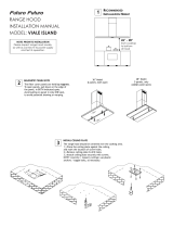
VENTING REQUIREMENTS
Determine which venting method is best for your application.
Ductwork can extend either through the wall or the roof.
The length of the ductwork and the number of elbows should
be kept to a minimum to provide efcient performance. The
size of the ductwork should be uniform. Do not install two
elbows together. Use duct tape to seal all joints in the ductwork
system. Use caulking to seal exterior wall or oor opening
around the cap.
Flexible ductwork is not recommended. If it is used,
each foot of exible ductwork used is equivalent to
two feet of straight metal ductwork when calculating
the ductrun length. Thus, a exible elbow equals two
standard elbows.
Make sure there is proper clearance within the wall or oor
for exhaust duct before making cutouts. Do not cut a joist or
stud unless absolutely necessary. If a joist or stud must be
cut, then a supporting frame must be constructed.
FOR MORE SPECIFIC DUCTWORK INFORMATION, GO
TO PAGE 4.
WARNING - To Reduce The Risk Of Fire, Use Only Metal
Ductwork.
ELECTRICAL REQUIREMENTS
A 120 volt, 60 Hz AC-only electrical supply is required on a
separate 15 amp fused circuit. A time-delay fuse or circuit
breaker is recommended. The fuse must be sized per local
codes in accordance with the electrical rating of this unit as
specied on the serial/rating plate located inside the unit
near the eld wiring compartment. THIS UNIT MUST BE
CONNECTED WITH COPPER WIRE ONLY. Wire sizes
must conform to the requirements of the National Electrical
Code, ANSI/NFPA 70 - latest edition, and all local codes and
ordinances. Wire size and connections must conform with the
rating of the appliance. Copies of the standard listed above
may be obtained from:
National Fire Protection Association
Batterymarch Park
Quincy, Massachusetts 02269
• Venting system MUST terminate outside the
home.
• DO NOT terminate the ductwork in an attic or
other enclosed space.
• DO NOT use 4" laundry-type wall caps.
• Flexible-type ductwork is not recommended.
• DO NOT obstruct the ow of combustion and
ventilation air.
• Failure to follow venting requirements may result
in a re.
This appliance should be connected directly to the fused
disconnect (or circuit breaker) through exible, armored or
nonmetallic sheathed copper cable. Allow some slack in the
cable so the appliance can be moved if servicing is ever nec-
essary. A UL Listed, 1/2" conduit connector must be provided
at each end of the power supply cable (at the appliance and
at the junction box).
When making the electrical connection, cut a 1 1/4" hole
in the wall. A hole cut through wood must be sanded until
smooth. A hole through metal must have a grommet.
WARNING - TO REDUCE THE RISK OF FIRE OR ELECTRIC
SHOCK, do not use this fan with any solid-state speed
control device.
WARNING - TO REDUCE THE RISK OF FIRE, ELECTRI-
CAL SHOCK, OR INJURY TO PERSONS, OBSERVE THE
FOLLOWING: Use this unit only in the manner intended
by the manufacturer. If you have any questions, contact
the manufacturer.
Before servicing or cleaning unit, switch power off at
service panel and lock the service disconnecting means
to prevent power from being switched on accidentally.
When the service disconnecting means cannot be locked,
securely fasten a prominent warning device, such as a
tag, to the service panel.
CAUTION: For General Ventilating Use Only. Do Not
Use To Exhaust Hazardous or Explosive Materials and
Vapors.
WARNING - TO REDUCE THE RISK OF FIRE, ELECTRI-
CAL SHOCK, OR INJURY TO PERSONS, OBSERVE THE
FOLLOWING: Installation Work And Electrical Wiring Must
Be Done By Qualied Person(s) In Accordance With All
Applicable Codes And Standards, Including Fire-Rated
Construction.
Sufcient air is needed for proper combustion and
exhausting of gases through the ue (chimney) of fuel
burning equipment to prevent backdrafting. Follow the
heating equipment manufacturer's guideline and safety
standards such as those published by the National Fire
Protection Association (NFPA), and the American Society
for Heating, Refrigeration and Air Conditioning Engineers
(ASHRAE), and the local code authorities.
When cutting or drilling into wall or ceiling, do not dam-
age electrical wiring and other hidden utilities.
Ducted fans must always be vented to the outdoors.
WARNING
• Electrical ground is required on this rangehood.
• If cold water pipe is interrupted by plastic,
nonmetallic gaskets or other materials, DO NOT
use for grounding.
• DO NOT ground to a gas pipe.
• DO NOT have a fuse in the neutral or grounding
circuit. A fuse in the neutral or grounding circuit
could result in electrical shock.
• Check with a qualied electrician if you are in doubt
as to whether the rangehood is properly grounded.
• Failure to follow electrical requirements may result
in a re.
WARNING
For residential use only.
!
!
Cold Weather installations
An additional back draft damper should be installed to minimize
backward cold air ow and a nonmetallic thermal break should be
installed to minimize conduction of outside temperatures as part of
the vent system. The damper should be on the cold air side of the
thermal break. The break should be
as close as possible to where the
vent system enters the heated portion of the house.

Version 03/08- Page 4
Includes: • Lower Chimney with holes for ducting • Ductless
Diverter • Vent Grates • Two Charcoal Filters
Ductless Conversion Kit/
Kit Pour Conversion Du Conduit
Stainless
White
Black
620000059
620000162
620000163
Replacement Charcoal Filters/Filtres au Charbon
6093034
High Ceiling Chimney Kit/
Kit D'extension Pour La Cheminée Plafond Haut
One 40” upper chimney (S) to replace 16
3/8”
upper chimney (S) that came with hood
Stainless
White
Black
620000070
620000164
620000165
OPTIONAL ACCESSORIES AVAILABLE/ACCESSOIRES POUR L’INSTALLATION
(B) 24" high, mounts to the wall beneath
the rangehood for a coordinated look
24" High Backsplash/Dosseret 24 po
30 x 24 Stainless
30 x 24 White
30 x 24 Black
36 x 24 Stainless
36 x 24 White
36 x 24 Black
6098835
6098836
6098837
6098815
6098816
6098817
(B) 30" high, mounts to the wall beneath
the rangehood for a coordinated look
30" High Backsplash/Dosseret 30 po
30 x 30 Stainless
36 x 30 Stainless
620000095
620000096

Version 03/08- Page 5
TOOLS NEEDED FOR INSTALLATION
• Saber Saw or Jig Saw
• Drill
• 1 1/4" Wood Drill Bit
• Pliers
• Phillips Screwdriver
• Flat Blade Screwdriver
• Wire Stripper or Utility Knife
• Metal Snips
• Measuring Tape or Ruler
• Level
• Pencil
• Caulking Gun
• Duct Tape
PARTS SUPPLIED FOR INSTALLATION
• 1 Hardware Package
• 1 Literature Package
PARTS NEEDED FOR INSTALLATION
• 2 Conduit Connectors
• Power Supply Cable
• 1 Wall or Roof Cap
• All Metal Ductwork
9 Feet Straight Duct
2 - 90˚ Elbows
Wall Cap
Total System
9.0 feet
10.0 feet
0.0 feet
19.0 feet
FIGURE 3
3.0 feet
5.0 feet
12.0 feet
0.0 feet
45˚ Elbow
90˚ Elbow
90˚ Flat Elbow
Wall Cap
FIGURE 2
CALCULATE THE DUCTRUN LENGTH
The ductrun should not exceed 35 equivalent feet
if ducted with the required minimum of 6" round
ductwork. Calculate the length of the ductwork
by adding the equivalent feet in FIGURE 2 for
each piece of duct in the system An example
is given in FIGURE 3.
For best results, use no more than three 90°
elbows. Make sure that there is a minimum of
24" of straight duct between elbows if more
than one is used. Do not install two elbows
together. If you must elbow right away, do it
as far away from the hood's exhaust opening
as possible.
WARNING
Because of the weight and size of the
rangehood canopy, two or more people
are needed to move and safely install the
rangehood canopy.
Failure to properly lift rangehood could
result in damage to the product or personal
injury.
PERSONAL INJURY HAZARD
PLAN THE INSTALLATION
This rangehood can be installed as either ducted or ductless. In a ducted
application, this rangehood can be vented through the wall or ceiling. To vent
through a wall, a 90° elbow is used. When installed ductless, the rangehood
vents out of grates on the sides of the chimney. Ductless installations require
a Ductless Conversion Kit, available from your dealer.
WARNING! BEFORE MAKING ANY CUTS OR HOLES FOR INSTALLATION,
DETERMINE WHICH VENTING METHOD WILL BE USED AND CAREFULLY
CALCULATE ALL MEASUREMENTS.
RANGEHOOD COMPONENTS
FIGURE 1
A. CANOPY SECTION
B. LOWER CHIMNEY COVER
C. UPPER CHIMNEY COVER
D. CANOPY MOUNTING BRACKETS
E. CANOPY MOUNTING BRACKET
F. MOUNTING SCREWS
G. CHIMNEY MOUNTING BRACKETS
H. DAMPER
I. CHIMNEY SCREWS
ADJUSTMENT SCREWS
!
G
I
H

Version 03/08- Page 6
1” min
16
3/8” max
22”
9
1/2”
36”
x
also consult cooktop
manufacturer's recommendation
upper
chimney
lower
chimney
canopy
x = distance from hood to cooktop
(varies depending on installation)
min - 24”, suggested max - 30”
cabinet base
FIGURE 4
19 1/4”
PREPARE THE WALL
1. Disconnect and move freestanding range from cabinet
opening to provide easier access to upper cabinet and rear
wall. Put a thick, protective covering over cooktop, set-in
range or countertop to protect from damage or dirt.
2. Determine and clearly mark with a pencil the center line
on the wall where the rangehood will be installed.
3. The canopy attaches to the wall by two mounting brackets
(1 in FIGURE 5). The canopy of the rangehood hangs on
the two brackets which must be mounted with the anges
on the top of the bracket and pointing away from the wall.
Before installing the brackets, the adjustment screws must
be installed into the bottom of the bracket. These two
screws are provided in the hardware package and have
hexagon heads with a slot for a at blade screwdriver.
The dimensions illustrate mounting the canopy 24" above
the cooking surface.
If a Backsplash is to be used with this rangehood, it must
be installed before the rangehood. Installation instructions
for the Backsplash are supplied in its box. The height
of the Backsplash will determine the bottom edge of
the canopy.
4. The chimney mounts by two brackets (2 in FIGURE 5).
Note the position of the brackets. The top bracket should
be installed about 1/8" away from the ceiling. The bottom
bracket must be installed at the bottom point of the upper
chimney sleeve.
Determine the proper location for each bracket and install
the brackets on the wall. MAKE SURE THAT THE BRACK-
ETS ARE SECURELY FASTENED TO THE WALL.
5. Determine and make all necessary cuts in the wall for the
ductwork. Install the ductwork before the rangehood.
6. Determine the proper location for the Power Supply
Cable (FIGURE 6). Use a 1 1/4" Drill Bit to make this
hole. Run the Power Supply Cable. Use caulking to seal
around the hole. DO NOT turn on the power until instal-
lation is complete.
INSTALLATION DIMENSIONS
The Synthesis chimneys are adjustable and designed to meet varying ceiling
heights as indicated in FIGURE 4. The chimneys can be adjusted for ceil-
ings between 7' 8 1/2" and 9' 5 7/8" depending on the distance between
the bottom of the hood and the cooktop (distance x in FIGURE 4).
FIGURE 5
FIGURE 6
30 MODELS
36 MODELS
For shorter ceilings,
have the chimney
cover(s) cut at a sheet
metal shop. For higher
ceiling installations, the
High Ceiling Chimney
Kit includes a new 40”
upper chimney which
would replace the 16
3/8” upper chimney that
came with the hood.
min & max ceiling height examples
x = 30"
min
8'
2 1/2"
max
9'
5 7/8"
x = 28"
min
8'
1/2"
max
9'
3 7/8"
x = 26"
min
7'
10 1/2"
max
9'
1 7/8"
x = 24"
min
7'
8 1/2"
max
8'
11 7/8"

Version 03/08- Page 7
3. Remove the cover from the eld wiring compartment. Remove
the wiring electrical knockout using a at-blade screwdriver. Feed
the Power Supply Cable through the electrical knockout.
4. Hang the canopy on the brackets (1 in FIGURE 8). There are
two rectangular holes on the rear of the canpoy. The brackets
pass through these holes and the canopy hangs from the anges
on the brackets. Due to the weight of the canopy, two people
should lift it to avoid injuries. Make sure that the canopy is
secure on the brackets before releasing.
5. Level the canopy. The height and level of the canopy can
be adjusted by rotating the adjustment screws (W in FIGURE
8) on each side of the blower inside the rangehood.
INSTALL THE RANGEHOOD
1. Remove the unit from the carton and place on a at surface
for assembly. Cover the surface to prevent accidental dam-
age. Remove all parts including the mounting hardware before
discarding the carton.
2. Remove the grease lters from the unit and set aside. The
grease lters are removed by pressing the handle in front of the
lter (FIGURE 7). When replacing, make sure that the lters are
properly positioned with the handles in front and visible.
6. Connect the Power Supply Cable to the rangehood. Attach
the White lead of the power supply to the White lead of the
rangehood with a twist-on type wire connector. Attach the Black
lead of the power supply to the Black lead of the rangehood with
a twist-on type wire connector. Connect the Green (Green and
Yellow) ground wire under the Green grounding screw.
7. Replace the eld wiring compartment cover and the grease
lters.
8. For ducted installations, the damper must be attached to the
exhaust opening on the top of the canopy. Connect the ductwork
and seal all connections with duct tape.
FOR DUCTLESS INSTALLATIONS
Do not use the DAMPER (I In FIGURE 1) for ductless
installations. The UPPER CHIMNEY COVER must be installed
rst, before the LOWER CHIMNEY DUCTLESS.
Ductless installations require a Ductless Conversion Kit. This
kit consists of a LOWER CHIMNEY DUCTLESS (A in FIGURE
9) with holes for the exhaust air, a DUCTLESS DIVERTER (C),
two VENT GRIDS (B) to cover the holes in the chimney cover,
and two CHARCOAL FILTERS (D). The DUCTLESS DIVERTER
must be installed before the LOWER CHIMNEY DUCTLESS
is attached (as indicated by the arrow in FIGURE 9). The
LOWER CHIMNEY COVER without holes (B in FIGURE 1)
should be discarded.
FIGURE 9
Once the LOWER CHIMNEY DUCTLESS with holes is installed,
the VENT GRIDS (B) are inserted into the holes (FIGURE 10).
B
Attach the CHARCOAL FILTERS to both sides of the blower (as
indicated in FIGURE 11). Install the grease lters.
FIGURE 10
FIGURE 11
FIGURE 8
FIGURE 7

Version 03/08- Page 8
FIGURE 14
9. The chimney must be attached to the body of the rangehood, as indicated in FIGURE 12. The UPPER CHIMNEY COVER (C)
must be installed rst, then the LOWER CHIMNEY COVER (B) wraps around it. Both sections are secured to the wall under the
CHIMNEY MOUNTING BRACKETS (H). Secure the UPPER CHIMNEY COVER to the MOUNTING BRACKETS with the CHIMNEY
SCREWS (J). Secure the LOWER CHIMNEY COVER to the CANOPY SECTION (A) with the CHIMNEY SCREWS (J).
FIGURE 12
10. Turn the power supply on. Turn on blower and light. If the rangehood does not operate, check that the circuit breaker is not
tripped or the house fuse blown. If the unit still does not operate, disconnect the power supply and check that the wiring connec-
tions have been made properly.
USE AND CARE INFORMATION
This rangehood system is designed to remove smoke, cooking vapors and odors from
the cooktop area.
For Best Results
Start the rangehood several minutes before cooking to develop proper airow. Allow the
unit to operate for several minutes after cooking is complete to clear all smoke and odors
from the kitchen.
Cleaning
The metal grease lters should be cleaned frequently in hot detergent solution or washed
in the dishwasher. Stainless steel cleaner should be used on stainless rangehoods.
Abrasives and scouring agents can scratch stainless steel nishes and should not be
used to clean nished surfaces.
Replacing the Lamps
Before attempting to replace the lamps, make sure that the light switch is turned off.
Remove the 2 screws (as indicated in FIGURE 14) that hold the light support and gently
pull the support down from the hood. Remove the lamp from the light support and replace
with new lamp. Replace the light support and x it into place with the 2 screws.
An alternative method to replace the lamps is to use a 1 1/4" suction cup (FIGURE 15).
Attach the suction cup to the bulb and pull rmly down on the bulb and replace with a
new lamp.
FIGURE 15

Version 03/08- Page 9
Rangehood Control Panel
The control panel is located in the middle under the canopy. The
position and function of each control button are noted below (FIG-
URE 13A FOR 3-SPEED 500 CFM MODELS, FIGURE 13B FOR
2-SPEED 280 CFM MODELS).
Light On/Off Button ( L )
On/Off switch for the halogen lights. Move the switch to "1" to turn
the light ON and to "0" to turn it OFF.
Blower On/Off Button ( M )
On/Off switch for the blower. Move the switch to "1" to turn the
blower ON and to "0" to turn it OFF.
Blower Speed Button ( V )
Speed control for blower. FOR 3-SPEED 500 CFM MODELS
(FIGURE 13A), move the switch to"1" for LOW speed, "2" for
MEDIUM speed and "3" for HIGH speed. FOR 2-SPEED 280 CFM
MODELS (FIGURE 13B), move the switch to"1" for LOW speed
and "2" for HIGH speed.
WIRING DIAGRAM FOR 3-SPEED 500 CFM MODEL
DIAGRAMME DE CÂBLAGE MODÈLE 3 VITESSE 500 PCM
• This rangehood uses 20 watt Halogen Lamps. / Cette hotte utilise les ampoule halogènes de 20 W.
WIRING DIAGRAM FOR 2-SPEED 280 CFM MODEL
DIAGRAMME DE CÂBLAGE MODÈLE 2 VITESSE 280 PCM
CONTROL PANELS AND WIRING DIAGRAMS
The Synthesis rangehood is available in two versions: a 3-speed 500
cfm version and a 2-speed 280 cfm version. Please check the speed
control under the canopy to note which version you own. The 3-speed
500 cfm version, will have options of speeds 1, 2, and 3. The 2-speed
280 cfm version, will only have options of speeds 1 and 2.
FIGURE 13A - 3-SPEED 500 CFM / 3 VITESSE 500 PCM FIGURE 13B - 2-SPEED 280 CFM / 2 VITESSE 280 PCM
PANNEAU DE COMMANDES & DIAGRAMMES DE CÂBLAGE
Le Synthesis est disponible dans deux versions : une version du
3 vitesse 500 pcm et une version du 2 vitesse 280 pcm. Veuillez
vérier la commande de vitesse sous la hotte pour noter quelle
version vous possédez. La version du 3 vitesse 500 pcm, aura des
options des vitesses 1, 2, et 3. La version du 2 vitesse 280 pcm,
aura seulement des options des vitesses 1 et 2.
Panneau de commandes
Le panneau de commandes est situé sur le moyen sous la hotte.
La position et la fonction de chaque bouton sont indiquées à la
FIGURE 13 (FIGURE 13A POUR MODÈLES 3-VITESSE 500 PCM,
FIGURE 13B POUR MODÈLES 2-VITESSE 280 PCM).
Bouton marche-arrêt de la lumière (L)
Interrupteur marche-arrêt pour la lumière. Régler à « 1 » pour mettre
en circuit (ON) et à « 0 » pour mettre hors circuit (OFF).
Bouton marche-arrêt du ventilateur (M)
Interrupteur marche-arrêt pour le ventilateur. Régler à « 1 » pour
mettre en circuit (ON) et à « 0 » pour mettre hors circuit (OFF).
Bouton de vitesse du ventilateur (V)
Commande de vitesse variable. POUR MODÈLES 3-VITESSE
500 PCM (FIGURE 13A), régler à « 1 » pour vitesse basse (LOW),
à « 2 » pour vitesse moyenne (MEDIUM) et à « 3 » pour vitesse
élevée (HIGH). POUR MODÈLES 2-VITESSE 280 PCM (FIGURE
13B), régler à « 1 » pour vitesse basse (LOW), et à « 3 » pour
vitesse élevée (HIGH).

Version 03/08- Page 10
FABER WARRANTY & SERVICE (SAVE FOR YOUR RECORDS)
All Faber products are warranteed against any defect in materials or workmanship for the
original purchaser for a period of 1 year from the date of original purchase. This warranty
covers labor and replacement parts. To obtain warranty service, contact the dealer from
whom you purchased the rangehood, or the local Faber distributor. If you cannot identify
a local Faber distributor, contact us at (508) 358-5353 for the name of a distributor in your
area.
The Following is not covered by Faber's warranty:
1. Service calls to correct the installation of your range hood, to instruct you how to use your
range hood, to replace or repair house fuses or to correct house wiring or plumbing.
2. Service calls to repair or replace range hood light bulbs, fuses or lters. Those
consumable parts are excluded from warranty coverage.
3. Repairs when your range hood is used for other than normal, single-family
household use.
4. Damage resulting from accident, alteration, misuse, abuse, re, ood, acts of God,
improper installation, installation not in accordance with electrical or plumbing codes, or
use of products not approved by Faber.
5. Replacement parts or repair labor costs for units operated outside the United States or
Canada, including any non-UL or C-UL approved Faber rangehoods.
6. Repairs to the hood resulting from unauthorized modications made to the
rangehood.
7. Expenses for travel and transportation for product service in remote locations and pickup
and delivery charges. Faber range hoods should be serviced in the home.
Record Your Information Below:
Serial #: __________________________
Date of Purchase: ______________
/