Page is loading ...

Natural Gas Conversion Kit
IMPORTANT
Read this document carefully before attempting installation
of this conversion kit. These instructions should be left with
the consumer for future reference.
For the following Coleman® Gas Barbecue Grills:
8100 Series (M/N 9992-643)
8200 Series (M/N 9992-644)
WARNING
• This Natural Gas conversion Kit must be installed only by a qualified
service technician.
• Gas supply system must be installed in accordance with the U.S.
National Fuel Gas Code.
• This appliance and its individual shut off valve must be disconnected
from the gas supply piping system during any system pressure test in
excess of 1/2 PSI (3.5 KPA).
• Use a system manual shut off valve to shut off the gas supply to this
gas appliance before continuing with installation procedures.
WARNING
• If the information in this document is not followed exactly, a fire or
explosion may result causing property damage, personal injury or loss
of life. Read the Coleman®
Gas Barbecue Use, Care & Assembly
Manual With Grill Lighting Instructions,
before attempting installation
of this conversion kit.
WARNING
• TURN OFF THE GAS SUPPLY!
DO NOT attempt to install this Natural Gas Conversion Kit
while the barbecue is in operation or is hot.
Installation and provision for combustion and ventilation air
must conform with the
National Fuel Gas Code, ANSI Z223.1
,
or
CAN/CGA-B149.1, Natural Gas Installation Code
, or
CAN/CGA-B149.2, Propane Installation Code
.
WARNING
A liquid propane tank, not connected for use with this gas barbecue,
shall not be stored in the vicinity of this or any other appliance.
Note: These instructions apply to
more than one model grill. The
parts included are designed for
your specific grill. The
illustrations may differ slightly
from model to model.
Turn off LP tank and disconnect
regulator from tank prior to servicing grill.
Connections must comply with local requirements and are the sole responsibility of the person performing
the work. A certified plumber must make connection to gas source. All codes must be followed.

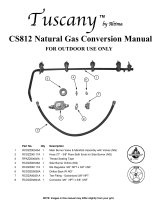
Part No. Qty Description
11
Main Burner Valve & Manifold Assembly (NG) 8100
1
Main Burner Valve & Manifold Assembly (NG) 8200
2 1 Hose 19" - 3/8" Flare Both Ends for Side Burner (NG)
3 1 Side Burner Valve Assembly - 12K BTU (NG)
4 1 Regulator 3/8" FNPT Threads (NG)
5 1 Nipple Pipe 3/8" NPT x 1.5"
6 1 Tee Fitting - Galvanized 3/8" NPT
7 2 Connector 3/8" MNPT x 3/8" Flare
8 1 Rear IR NG Orifice
9 1 3/8" Street Elbow
10 1 Pipe Sealant (4ml)
11 1 NG Converstion Sticker
12 1 3/8 FNPT to 3/8" Flare
*your part may differ in appearance, depending on size of grill
8
7
6
5
4
3
2
1*
9
10
11
12
2
Natural Gas Conversion Instructions

Tools Needed:
Phillips head screwdriver
1/4" nut driver *
9/16" wrench
Adjustable wrench
Fig 4
Fig 1
Fig 2
Fig 3
Rear Heat Shield
Screws
Heat Tents
Screws
* 1/4” socket set with extension can also be used.
Natural Gas Conversion Instructions
Be sure gas supply is off, the knobs are in the off
position and the grill is cool.
1. Remove cooking grates and heat tents (Fig. 1).
2. Remove the screws holding the rear heat
shield in place. Lift out rear heat shield and set
aside (Fig. 2).
3. Remove the two screws holding each electrode in
place (Fig. 3).
4. Lay igniters on floor of grill (Fig. 4).
3

Fig 5
Fig 6
Side Screws
(Repeat on left side).
Screws
under lip
Fig 8
Fig 7
Tabs
Natural Gas Conversion Instructions
5. Remove the screws from the bottom of the heat
shield, holding the front heat shield in place. The
screws are located under the bottom lip of the
shield (Fig. 5).
6. Remove the two side heat shield screws
located under the bottom lip of the heat shield.
There is one screw on each side (Fig. 6).
7. Remove the front heat shield (Fig. 7).
8. Grasp and push the burner(s) towards the rear
of the grill to detach the burner from the
valves (Fig. 8).
9. Angle the burners up and remove (Fig. 8).
4

Fig 10
Fig 14
Fig 9
Fig 11
Fig 13
Manifold
Gas Inlet Flex Line
Flex Line
Fig 12
Manifold
Screws
Natural Gas Conversion Instructions
10. Disconnect the right side flexline from the mani-
fold using the adjustable wrench. This will free
up the right side of the manifold (Fig. 9).
11. Disconnect the left side flexline from the back
infrared valve using an adjustable wrench. This
will free up the left side of the manifold (Fig. 10).
12. Remove the control knobs from the front of the
grill (Fig. 11).
13. Remove the two screws holding each bezel in
place on the control panel (Fig. 12).
14. Remove the bezels from the front control panel.
Note: The small bezel stays in place (Fig. 13).
15. Remove manifold from grill body (Fig. 14).
You are now ready to install
the new NG manifold.
5

Fig 15
Fig 17
Fig 18
Fig 19
Burners fully
over valves
Rear Heat Shield
Control Knob
Stems
Fig 16
Manifold
Natural Gas Conversion Instructions
16. Start by placing the new manifold into the grill
body with the control knob stems going outward
through control panel front (Fig. 15).
17. Reattach the bezels to the manifold with the two
screws. Make sure that "off" is facing up on the
bezel. (Fig. 12 & 13).
18. Reattach the flexline on the right of the grill to
the new manifold using the adjustable wrench
(See Fig. 9 on previous page).
19. Reattach the flexline on the left of the grill to the
back infrared valve using an adjustable wrench
(Fig. 16).
20. Reattach the control knobs onto the manifold
stems, making sure the arrow is facing upwards
(See Fig. 11 on previous page).
21. Reinstall burners into the grill body. Line up the
burners with the valves on the manifold, making
sure they are level (Fig. 17 & 18).
22. Reattach the electrode and their heat shields to
the burners (Fig. 2, 3, and 4).
23. Reattach the rear heat shield before attaching
the front heat shield to be sure the burners
remain over the valves (Fig. 19).
24. Reinstall the front heat shield (Fig. 5, 6, and 7).
25. Reinstall the heat tents (Fig. 1).
26. Reinstall the cooking grates.
6
Valves
Burners

Fig 20
Fig 21
Fig 22
Fig 23
Fig 24
Brass Flare
Fitting
Brass Flare
Fitting
Natural Gas Conversion Instructions
Installing the NG regulator
1. Remove the hose from the brass flare fitting
using an adjustable wrench. Located inside the
cart on bottom of grill head (Fig. 20).
Remaining hose end still connected will be
removed later.
2. Remove the brass flare fitting from the gas pipe
(Fig. 21).
Note: For the following steps, the supplied pipe
sealant needs to be applied to all pipe
threads before the fittings are attached.
Pipe sealant should not be used on any
flared fittings!
3. Remove the grommet in the side of the cart by
pressing in on the side with your fingers (Fig. 22).
4. Attach the tee fitting to the gas pipe as shown.
Make sure to apply pipe sealant before attaching
fitting. Tighten with wrench (Fig. 23).
5. Attach the 3/8" MNPT to flared 90° elbow to the
tee fitting as shown. Remember to apply pipe
sealant to the pipe threads.
Tighten with wrench (Fig. 24).
7

Fig 25
Fig 26
Fig 27
Fig 28
Fig 29
Natural Gas Conversion Instructions
6. Attach the 3/8" street elbow to the bottom of the
bottom of the tee connector. Make sure to apply
pipe sealant before attaching. Tighten with
wrench (Fig. 25).
7. Reinsert the grommet in the side of the
cart (Fig. 22).
8. Attach one end of the supplied hose to the
flared fitting on the side of the tee
connector (Fig. 26 and 27).
9. Assemble the 3/8" pipe nipple to the NG
regulator. Assemble the 3/8" FNPT to flared
fitting to the regulator. Use pipe sealant and
wrench tighten (Fig. 28).
10. Assemble the NG regulator with fittings to the
3/8" street elbow. The regulator should point
toward the rear of the grill. Use pipe sealant
and wrench tighten (Fig. 29).
Note: Pay attention to arrow on the NG
regulator indicating direction of gas flow.
The arrow should point toward the grill.
Remember to apply pipe sealant!
This completes the NG regulator installation.
8

Fig 30
Fig 31
Fig 32
Fig 33
Fig 34
Natural Gas Conversion Instructions
Converting the Rear Infrared Burner to NG
1. Remove the four screws on the inside of the grill
that hold the rear infrared cover in place (Fig. 30).
2. Close the grill hood slowly.
3. Remove the two screws from the back infrared
cover, located on the back of the grill (Fig. 31).
4. Grasp rear infrared cover and remove it from the
grill.
5. Disconnect flex line and twist orifice elbow to
remove LP orifice (Fig. 32 & 33).
6. Completely remove the LP orifice from the flared
fitting and discard the LP orifice (Fig. 33).
7. Identification of the NG orifice (Fig. 34).
Note: NG orifice has a larger opening
compared to the LP orifice being
replaced.
8. Install the NG orifice into the flared fitting and
tighten completely with an adjustable wrench
(Fig. 33).
9. Reconnect the flexline (Fig. 32).
10. Replace the rear infrared cover. Install the two
screws on the back infrared cover, located on the
back of the grill (Fig. 31).
11. Open the grill hood slowly.
12. Reinstall the four screws on the inside of the grill
that hold the rear infrared cover in place (Fig. 30).
This completes the Rear Infrared Burner Conversion.
9
Rear
Screws

Fig 36
Underside of side
burner shelf
Fig 35
Valve Assembly
Fig 37
Natural Gas Conversion Instructions
Converting the Side Burner to NG
1. Remove side burner grate, porcelain cap and
burner head (Fig. 35).
2. Remove and discard the LP regulator hose
attached to the side burner LP valve
assembly (Fig. 36).
(Located on the under side of the side burner).
3. Remove the control knob from the front of the
side burner (Fig. 37).
(It should pull off by hand).
10

Fig 38
Fig 39
Fig 40
Igniter Wire
Fig 41
Casting
Side Burner Valve Assy
Fig 42
Casting
Side Burner Valve Assy
Screws
Natural Gas Conversion Instructions
4. Remove the two screws holding the bezel and
valve in place. Remove bezel from the front of
the side burner (Fig. 38).
5. Remove the two screws holding the side
burner LP valve assembly in place. This will
free up the assembly (Fig. 39 & 40).
6. Disconnect the igniter wire from the side burner
electrode (Fig. 40).
7. Holding the assembly securely, remove side
burner valve assembly from casting. Replace
with new side NG side burner valve
assembly (Fig. 41 & 42).
11

Fig 43
Fig 44
Bezel
Fig 45
Underside of
side burner
Natural Gas Conversion Instructions
8. Install the NG valve assembly to the underside
of the side burner with the two screws previously
removed (Fig. 43).
Note: Make sure the NG valve is facing towards
the front of the side burner and the valve
stem is inserted into the hole.
9. Reattach the bezel to the front of the side burner
and the NG valve with the two screws previously
removed (Fig. 44).
Note: Make sure the bezel is installed in the
correct position. The "H" will be facing
the ignitor.
10. Reattach the control knob.
11. Connect the end of the new gas supply hose to
the side burner valve assembly (Fig. 45).
12. Reattach the side burner igniter wire to the
electrode.
This completes the side burner conversion.
12
“H”
Screw

Label the Grill
1. Apply conversion label 9992-461 on the grill,
next to the lighting instruction label.
Note: At the completion of the
conversion, a leak test should be
performed on all fittings. See
Use and Care manual for leak
testing procedure.
Installation is now complete.
Enjoy your grill safely.
Natural Gas Conversion Instructions
13
Fig 46

__________________________________________ __________________________________________
__________________________________________ __________________________________________
__________________________________________ __________________________________________
__________________________________________ __________________________________________
__________________________________________ __________________________________________
__________________________________________ __________________________________________
__________________________________________ __________________________________________
__________________________________________ __________________________________________
__________________________________________ __________________________________________
__________________________________________ __________________________________________
__________________________________________ __________________________________________
__________________________________________ __________________________________________
__________________________________________ __________________________________________
__________________________________________ __________________________________________
____________________________________________________________________________________
__________________________________________ __________________________________________
__________________________________________ __________________________________________
__________________________________________ __________________________________________
__________________________________________ __________________________________________
__________________________________________ __________________________________________
__________________________________________ __________________________________________
__________________________________________ __________________________________________
__________________________________________ __________________________________________
__________________________________________ __________________________________________
__________________________________________ __________________________________________
__________________________________________ __________________________________________
__________________________________________ __________________________________________
__________________________________________ __________________________________________
NOTES
Natural Gas Conversion Instructions
14

__________________________________________ __________________________________________
__________________________________________ __________________________________________
__________________________________________ __________________________________________
__________________________________________ __________________________________________
__________________________________________ __________________________________________
__________________________________________ __________________________________________
__________________________________________ __________________________________________
__________________________________________ __________________________________________
__________________________________________ __________________________________________
__________________________________________ __________________________________________
__________________________________________ __________________________________________
__________________________________________ __________________________________________
__________________________________________ __________________________________________
__________________________________________ __________________________________________
____________________________________________________________________________________
__________________________________________ __________________________________________
__________________________________________ __________________________________________
__________________________________________ __________________________________________
__________________________________________ __________________________________________
__________________________________________ __________________________________________
__________________________________________ __________________________________________
__________________________________________ __________________________________________
__________________________________________ __________________________________________
__________________________________________ __________________________________________
__________________________________________ __________________________________________
__________________________________________ __________________________________________
__________________________________________ __________________________________________
__________________________________________ __________________________________________
NOTES
Natural Gas Conversion Instructions
15

9992-448 (6/21/06)
The Coleman Company, Inc. • 3600 North Hydraulic
Wichita, KS 67219 U.S.A.
1-800-356-3612 • TDD: 316-832-8707
www.coleman.com
©2006 The Coleman Company, Inc. All rights reserved.
Coleman® and are registered trademarks of
The Coleman Company, Inc.
/