Behringer BCA2000 User manual
- Category
- Musical Instruments
- Type
- User manual
This manual is also suitable for

Version 1.3 July 2006
Users Manual
B-CONTROL AUDIO BCA2000

2
B-CONTROL AUDIO BCA2000
This symbol, wherever it appears, alerts you to the
presence of uninsulated dangerous voltage inside
the enclosurevoltage that may be sufficient to
constitute a risk of shock.
This symbol, wherever it appears, alerts you to
important operating and maintenance instructions
in the accompanying literature. Please read the
manual.
IMPORTANT SAFETY INSTRUCTIONS
CAUTION: To reduce the risk of electric shock, do not remove
the top cover (or the rear section). No user
serviceable parts inside; refer servicing to qualified
personnel.
WARNING: To reduce the risk of fire or electric shock, do not
expose this appliance to rain and moisture. The
apparatus shall not be exposed to dripping or
splashing and no objects filled with liquids, such
as vases, shall be placed on the apparatus.
DETAILED SAFETY INSTRUCTIONS:
1) Read these instructions.
2) Keep these instructions.
3) Heed all warnings.
4) Follow all instructions.
5) Do not use this apparatus near water.
6) Clean only with dry cloth.
7) Do not block any ventilation openings. Install in
accordance with the manufacturers instructions.
8) Do not install near any heat sources such as radiators,
heat registers, stoves, or other apparatus (including
amplifiers) that produce heat.
9) Do not defeat the safety purpose of the polarized or
grounding-type plug. A polarized plug has two blades
with one wider than the other. A grounding type plug
has two blades and a third grounding prong. The wide
blade or the third prong are provided for your safety. If
the provided plug does not fit into your outlet, consult
an electrician for replacement of the obsolete outlet.
10) Protect the power cord from being walked on or
pinched particularly at plugs, convenience receptacles,
and the point where they exit from the apparatus.
11) Only use attachments/accessories specified by the
manufacturer.
12) Use only with the cart, stand, tripod, bracket, or table
specified by the manufacturer, or sold with the
apparatus. When a cart is used, use caution when moving
the cart/apparatus combination to avoid injury from
tip-over.
13) Unplug this apparatus during lightning storms or
when unused for long periods of time.
14) Refer all servicing to qualified service personnel.
Servicing is required when the apparatus has been
damaged in any way, such as power supply cord or plug
is damaged, liquid has been spilled or objects have fallen
into the apparatus, the apparatus has been exposed to
rain or moisture, does not operate normally, or has been
dropped.
15) CAUTION - These service instructions are for use by
qualified service personnel only. To reduce the risk of
electric shock do not perform any servicing other than
that contained in the operation instructions unless you
are qualified to do so.

3
B-CONTROL AUDIO BCA2000
BCA2000
B-CONTROL AUDIO
High-Speed USB 2.0 Multi-Channel Audio/MIDI Control Interface with ADAT
®
Support, Surround
Outputs and Extensive Monitor Control Section
s High-performance analog input section with 2 state-of-the-art, studio-grade IMP Invisible Mic Preamps,
+48 V phantom power plus Line and Hi-Z Guitar inputs
s Ultra-flexible input/output configuration supported by a comprehensive, audio-routing LED indicator plus
button (status) LEDs
s Adjustable studio-grade analog input dynamic control (noise gate and limiter) prevents distorted input
signals or A/D converter overload
s Fully equipped USB/MIDI interface with 1 MIDI In / 2 MIDI Outs individually selectable for 16 / 32 MIDI
channels
s Versatile digital input and output formats like ADAT
®
, ADAT
®
S/MUX, AES/EBU and S/PDIF, including
Dolby
®
Digital- and DTS
®
support
s Simultaneous use of 3 analog input sources (1 mono + 1 stereo), digital input sources plus full
multi-channel playback at 24-bit/96 kHz
s High-resolution 2 x 12-segment LED stereo in/out level meter
s High-speed USB 2.0 interface with 24-bit/96 kHz, supports 8 in + 8 out channels simultaneously
(analog and digital) with low-latency ASIO 2 and WDM drivers
s Fully equipped master and monitor sections with 100-mm faders, individual level controls for 2 speakers,
2 phones and Direct monitor function plus separate Dim, Mute and Mono functions
s High-quality components and exceptionally rugged construction ensure long life
s Conceived and designed by BEHRINGER Germany
All Trademarks mentioned belong to their respective owners and are not affiliated with BEHRINGER

4
B-CONTROL AUDIO BCA2000
TABLE OF CONTENTS
1. INTRODUCTION ......................................................... 5
1.1 Before you get started ................................................... 5
1.1.1 Shipment ............................................................... 5
1.1.2 Initial operation ...................................................... 5
1.1.3 Online registration ................................................ 5
1.2 System requirements ..................................................... 5
1.2.1 Outline of functions for High-Speed USB ..............
(USB 2.0) .............................................................. 5
1.2.2 Outline of functions for Full-Speed USB .............. 5
2. INSTALLATION ........................................................... 6
2.1 Hardware connection/driver installation ........................ 6
2.2 Control panel software .................................................. 6
3. CONTROL ELEMENTS AND CONNECTIONS ............. 8
3.1 Control surface ............................................................... 8
3.1.1 Input section ......................................................... 8
3.1.2 Main/Monitor section ............................................ 9
3.1.3 Dynamics section ................................................. 9
3.2 The rear panel .............................................................. 10
4. AUDIO ROUTING ...................................................... 11
4.1 Input routing .................................................................. 11
4.2 Output routing ............................................................... 12
4.2.1 Output routing in ADAT
®
mode ........................... 12
4.2.2 Output routing in 2-CHANNEL mode .................. 13
4.3 First steps with the B-CONTROL ................................. 13
5. APPLICATIONS ........................................................ 14
5.1 Mobile studio ................................................................. 14
5.2 Project studio ................................................................ 15
5.3 Professional studio ....................................................... 16
5.4 Basis recording session .............................................. 17
5.5 Multi-channel recording with 5.1 surround monitoring 18
6. CONNECTIONS AND FORMATS ............................... 20
6.1 Glossary ....................................................................... 20
6.2 Audio connections ....................................................... 22
6.3 Digital inputs and outputs ............................................. 22
6.4 MIDI connectors ............................................................ 23
7. SPECIFICATIONS ..................................................... 23
8. WARRANTY .............................................................. 24
FCC COMPLIANCE INFORMATION .............................. 25
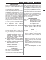
Dear Customer,
welcome to the team of
BEHRINGER users, and
thank you very much for
expressing your confi-
dence in us by purchas-
ing the B-CONTROL.
Writing this foreword
for you gives me great
pleasure, because it
represents the culmi-
nation of many months of
hard work delivered by
our engineering team to
achieve a very ambitious
goal: to deliver an
outstanding USB audio/
MIDI control interface,
whose extremely flexible
connections let it assume
the central control role in almost any computer studio. The task
of designing our new B-CONTROL certainly meant a great deal
of responsibility, which we assumed by focusing on you, the
discerning computer user and musician. Meeting your
expectations also meant a lot of work and night shifts. But it was
fun, too. Developing a product usually brings a lot of people
together, and what a great feeling it is when all who participated
in such a project can be proud of what theyve achieved.
It is our philosophy to share our enjoyment with you, because
you are the most important member of the BEHRINGER team.
With your highly competent suggestions for new products youve
made a significant contribution to shaping our company and making
it successful. In return, we guarantee you uncompromising quality
as well as excellent technical and audio properties at an extremely
reasonable price. All of this will enable you to give free rein to
your creativity without being hampered by budget constraints.
We are often asked how we manage to produce such high-
quality equipment at such unbelievably low prices. The answer
is quite simple: its you, our customers! Many satisfied customers
mean large sales volumes enabling us to get better purchasing
terms for components, etc. Isnt it only fair to pass this benefit on
to you? Because we know that your success is our success
too!
I would like to thank all of you who have made the B-CONTROL
possible. You have all made your own personal contributions,
from the developers to the many other employees at this company,
and to you, the BEHRINGER user.
My friends, its been worth the effort!
Thank you very much,
Uli Behringer
FOREWORD

5
B-CONTROL AUDIO BCA2000
1. INTRODUCTION
Welcome to the family of BCA2000 users and thank you for
expressing your confidence in BEHRINGER products by
purchasing the B-CONTROL.
The BCA2000 is an extremely flexible USB audio and MIDI interface
with a unique design concept that will effectively support you in
your computer-based music and audio endeavors.
Our goal in designing the B-CONTROL was to create an intuitive,
flexible and optically attractive product that gives you comfortable
control (instead of those tiny knobs and buttons found on so
many interfaces) and plenty of connectivity options, so that you
can concentrate on whats really important: your music. Thats
why we started by creating a mixing console with a clean,
concise layout: ultra-precise 100-mm faders, a high-resolution
LED level display, rugged construction, our ultra low-noise IMP
invisible microphone preamplifiers and an extensive monitor
sectionfeatures youve come to expect from a BEHRINGER
mixing console. Then we added a multitude of interface functions:
full 24-bit/96 kHz support in multichannel operation, optical and
coaxial digital connectors that support all common formats,
simultaneous reproduction of eight input and eight output channels,
6 analog outputs for subgroup/stem or 5.1 surround reproduction
and a simultaneously usable USB MIDI interface. All of this makes
the BCA2000 a one-of-a-kind high-speed USB audio/MIDI
interface featuring a comfortable mixing console design.
+ The following users manual is intended to
familiarize you with the units control elements,
so that you can master all the functions. After having
thoroughly read the users manual, store it at a safe
place for future reference.
1.1 Before you get started
1.1.1 Shipment
The BCA2000 was carefully packed at the assembly plant to
assure secure transport. Should the condition of the cardboard
box suggest that damage may have taken place, please inspect
the unit immediately and look for physical indications of damage.
+ Damaged equipment should NEVER be sent directly
to us. Please inform the dealer from whom you
acquired the unit immediately as well as the
transportation company from which you took
delivery. Otherwise, all claims for replacement/
repair may be rendered invalid.
+ To assure optimal protection of your B-CONTROL
during use or transport, we recommend utilizing a
carrying case.
+ Please always use the original packaging to avoid
damage due to storage or shipping.
+ Never let unsupervised children play with the
B-CONTROL or with its packaging.
+ Please dispose of all packaging materials in an
environmentally friendly fashion.
1.1.2 Initial operation
Please make sure the unit is provided with sufficient ventilation,
and never place the B-CONTROL on top of an amplifier or in the
vicinity of a heater to avoid the risk of overheating.
A power supply unit which meets the necessary safety
requirements is enclosed for connecting the B-CONTROL to the
mains.
1.1.3 Online registration
Please, do remember to register your new BEHRINGER equipment
right after your purchase by visiting www.behringer.com and
kindly read the terms and conditions of our warranty carefully.
Should your BEHRINGER product malfunction, our goal is to have
it repaired as quickly as possible. To arrange for warranty service,
please contact the retailer from whom the equipment was
purchased. Should your BEHRINGER dealer not be located in
your vicinity, you may directly contact one of our subsidiaries.
Corresponding contact information is included in the original
equipment packaging (Global Contact Information/European
Contact Information). Should your country not be listed, please
contact the distributor nearest you. A list of distributors can be
found in the support area of our website (www.behringer.com).
Registering your purchase and equipment with us helps us
process your repair claims quicker and more efficiently.
Thank you for your cooperation!
1.2 System requirements
Operating system Windows
®
XP with Service Pack 2
Computer Windows
®
PC with USB connector
Processor Intel Pentium Processor 1.2 GHz or better
256 MB RAM (512 MB recommended)
Chip set Intel chip set recommended
USB modes Full eight-channel input/output operation
with 24-bit/96 kHz with USB 2.0
interface (High-Speed USB, 480 Mbps)
+ When connecting to a Full-Speed USB interface
(12 Mbps, also known as USB 1.1), only limited
operation is possible (see 1.2.2).
1.2.1 Outline of functions for High-Speed USB
(USB 2.0)
Audio inputs:
s Simultaneous recording of three analog signals (1 x mono,
1 x stereo) and one stereo digital signal.
s Alternatively, simultaneous recording of eight audio channels
at 44.1 kHz or at 48 kHz with the optical input in ADAT
®
format (four-channel recording at 24-bit/96 kHz with
ADAT
®
S/MUX).
s Support for S/PDIF, AES/EBU, ADAT
®
, and ADAT
®
S/MUX
digital audio formats.
Audio outputs:
s Simultaneous reproduction of eight output signals (six
analog and one stereo digital signal). The stereo digital
output signal is available in parallel on both the coaxial and
optical outputs.
s Alternatively, reproduction of eight digital signals at 44.1 or
48 kHz via the optical output in ADAT
®
format (four-channel
reproduction at 24-bit/96 kHz with ADAT
®
S/MUX), also
available in parallel on analog outputs 1 to 6 and the coaxial
digital output.
s Support for S/PDIF, AES/EBU, ADAT
®
, ADAT
®
S/MUX,
DOLBY
®
DIGITAL and DTS
®
digital audio formats.
MIDI:
s Simultaneous use of all MIDI inputs and outputs.
1. INTRODUCTION

6
B-CONTROL AUDIO BCA2000
1.2.2 Outline of functions for Full-Speed USB
Audio inputs:
s Simultaneous recording of three analog signals (1 x mono,
1 x stereo) and one stereo digital signal.
s Alternatively, simultaneous recording of four ADAT
®
channels
at 44.1 and 48 kHz.
s Support of S/PDIF, AES/EBU and ADAT
®
digital audio formats.
Audio outputs:
s Simultaneous reproduction of two stereo signals, available
in parallel on the analog and digital outputs.
s Alternatively, reproduction of four ADAT
®
channels at 44.1
kHz or 48 kHz via the optical output, also available in parallel
on all analog outputs and on the coaxial digital output.
s Support of S/PDIF, AES/EBU, ADAT
®
, DOLBY
®
DIGITAL and
DTS
®
digital audio formats.
MIDI:
s Additionally, simultaneous use of all MIDI functions.
2. INSTALLATION
2.1 Hardware connection and
driver installation
s Before you start the setup.exe program, close all
applications, including any virus scanners
s Via a USB port, connect the BCA2000 to your computer.
However, do not yet power up the B-CONTROL!
s Unzip the setup.zip file. To start the installation process,
double click the setup.exe icon. Then, follow the on-
screen instructions!
+ Before you continue, switch off the BCA2000. At the
appropriate step of the installation process,
setup.exe will prompt you to switch on the BCA2000.
If you opened Found New Hardware Wizard, close
this wizard.
+ Although setup.exe repeats the installation process
for each driver, setup.exe guides you through each
step of the relevant installation processes.
+ If the message Driver software has not passed
Windows
®
-Logo testing appears during the
installation process, ignore this message and click
Continue installation.
2.2 Control panel software
The control panel software gives you access to all global
B-CONTROL settings and is integrated into your computer system
during driver installation. To launch the control panel software,
click on the BCA2000 control panel symbol in the task bar at the
bottom right of your screen.
Any changes to settings in the control panel are immediately
effective, with the exception of the Driver Latency/Buffer Size
setting: if you move the fader, a message pops up informing you
that the new latency/buffer size setting will be effective after
you close the control panel.
ADAT
®
96 kHz operation is indicated in all windows (right field),
along with the current sample rate, ASIO and USB driver version
and firmware version.
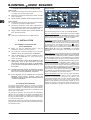
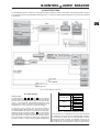
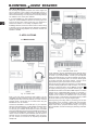
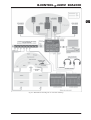
SETUP window:
Fig. 2.1: Control panel software SETUP window
The following settings can be made in the Setup window:
Dig. 2-Ch. Output Format: The format for two-channel digital
output is switchable between AES/EBU and S/PDIF. Format
selection has an effect on both the coaxial and the optical output,
unless the OPTICAL OUT button ( ) is set to ADAT.
Clock Select: Selects a wordclock synchronization source. DIG.
2-CH./ADAT enables external synchronization via the optical or
coaxial input (which input serves as the synchronization source
is determined by the DIGITAL IN button ( ). ADAT
®
synchronization is only possible via the optical input with an
ADAT
®
signal present. To synchronize to a 96 kHz signal, select
S/MUX (ADAT IN). When set to INTERNAL, the BCA2000
synchronizes itself to the sample rate selected in your audio
software.
MIDI Port B Select: In this field, MIDI OUT B can be configured as
a MIDI THRU. When THRU mode is activated, this output forwards
incoming data with no additional processing. If OUT is selected,
the OUT B/THRU connector can be addressed by the computer
as a second MIDI output, giving you a total of 32 MIDI channels.
ASIO Direct Monitoring: This setting determines which signal is
monitored during recording. If Digital is selected, only the input
signal will be heard with no latency (delay). In Analog mode,
both the recorded tracks and the input signal (the signal being
recorded) are heard simultaneously; the mix between the two
can be adjusted via the MONITOR BALANCE fader ( ). In both
modes, only the output signal is heard when the audio software
is in playback mode. Switching between recording and playback
mode is accomplished via your audio software.
Driver Latency/Buffer Size: Here you can adjust the latency
(system-inherent audio signal delay) in order to optimize your
computers performance. The lower the latency (and
consequently the buffer size), the higher the CPU usage. When
the processor workload is too high, you will notice frequent
pauses in audio playback (as the processor catches up). If you
change this setting, a message will appear stating that your
changes will take effect only after you close the control panel.
2. INSTALLATION

7
B-CONTROL AUDIO BCA2000
WDM window:
Fig. 2.2: Control panel software WDM window
If your music applications do not support ASIO, use the WDM
device driver (most software media players).
On this page, all parameters apply only to the WDM device driver.
The Windows
®
operating system suggests all default parameter
settings. However, this does not mean that the operating system
will accept these default settings. The maximum value that is
available for each parameter depends on parameter settings in
the Windows
®
operating system and in the applications that you
use.
High parameter settings can lower the performance of non-
audio applications. If the main task of your computer is to run
audio applications, select high values for the parameters. In non-
audio applications (games, for example), select low values for
the parameters.
Note: In USB1.1 mode, the following parameter settings are not
available: max. resolution: 16 bit, max. sample rate: 48000, max.
number of outputs: 4.
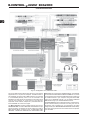
USB INFO window:
Fig. 2.3: Control panel software USB INFO window
The USB INFO window allows you to adapt the B-CONTROL to
the USB connection you are using. If you are running your
B-CONTROL on Full-Speed USB, only limited functionality is
available. The table shows which input/output combinations are
possible with your USB interface.
If USB2.0 mode does not operate perfectly on your computer,
activate the Force USB1.1 mode in the left column. Via Force
USB1.1, the computer works in Full Speed mode (USB1.1), even
if the BCA2000 is connected to a USB 2.0 interface.
Each time you activate or, alternatively deactivate Force USB1,
switch the BCA2000 off. Then, switch the BCA2000 on again.
The first time you do this, the software installs new drivers.
Note: In USB1 mode, all features are not available (see ch. 1.2.2).
2. INSTALLATION
BLOCK DIAGRAM window:
Fig. 2.4: Control panel software BLOCK DIAGRAM window
The BLOCK DIAGRAM window shows the entire audio signal
flow of your BCA2000 and serves as a good source of
information if you dont have the users manual handy.

8
B-CONTROL AUDIO BCA2000
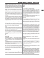
3. CONTROL ELEMENTS AND CONNECTIONS
The various control elements of your BCA2000 are described in this chapter. All controls and connections are explained in detail, and
there are several useful tips on their use.
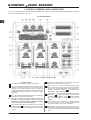
3.1 Control surface
Fig. 3.1: The BCA2000s control elements
3.1.1 Input section
The TRIM control adjusts the level of input signals.
The CLIP and SIGNAL LEDs show the input signal level.
SIGNAL illuminates when there is an incoming signal,
whereas CLIP illuminates when the level is too high and
could cause distortion. If this happens, turn the TRIM control
counterclockwise slightly and the CLIP LED no longer
illuminates.
The +48 V button activates phantom power for a condenser
microphone connected to the XLR input.
+ Be sure to mute your audio system before you
activate the phantom power supply to prevent
audible and potentially damaging switch-on thumps
from reaching your monitor speakers.
PAN positions the signal in the stereo field. If the LINE
STEREO button is pressed, the PAN control adjusts
the BALANCE between L and R signals in the stereo input
channel.
The 100-mm channel faders control the level of the input
signal that is routed to the A/D converter.
MIC A and LINE L are the two possible positions of this
switch, which controls the input that is routed to a particular
channel. The corresponding LEDs indicate the input you
selected. If GUITAR HI-Z switch is pressed, the left
MIC A/LINE L switch is deactivated.
The GUITAR (HI-Z) button feeds the guitar signal from the
guitar input into the mono input channel. This button
overrides the MIC A/LINE L button : when GUITAR
(HI-Z) is activated, MIC A or LINE L can no longer be
selected.
The GUITAR IN (HI-Z) input allows you to directly connect
an electric guitar or other high-impedance signal
(e.g. passive pickups of acoustic instruments).
MIC B/LINE R is the input selection button for the stereo
input channel. Select between MIC B and LINE R (the right
line input). The corresponding LEDs indicate the selected
input.
3. CONTROL ELEMENTS AND CONNECTIONS

9
B-CONTROL AUDIO BCA2000
The LINE STEREO button feeds the stereo signal of both
line inputs ( ; see page 10) into the stereo input channel.
If the LINE STEREO button is pressed, channel two becomes
a stereo channel, and the PAN control assumes the BALANCE
function (see 4 above). This allows a maximum of three input
signals (1 x mic/guitar and 1 x stereo) to be processed
simultaneously (see also ch. 4.1).
3.1.2 Main/Monitor section
The 100-mm MAIN fader controls the output signal
(MAIN OUT).
The PHONES controls adjust the volume of connected
headphones.
The CTRL ROOM control adjusts the volume of the control
room outputs .
The PHONES outputs (individually adjustable; see 12) are
used for connecting headphones. You can listen to the
main output, the input sum or the mix of both signals.
The MONITOR button activates the direct monitoring
function, and the DIR I/O LED lights up. When the button is
not pressed, auto monitoring is active.
With auto monitoring, switching between input and recorded tracks
is done automatically by your host software (audio sequencer/
software mixer). System-induced latencies occur between the
recorded signal and computer playback. To avoid this, you can
switch to DIRECT I/O during a recording session. This provides
you with delay-free signal routing (see also chapter 4.3).
LISTEN switches the monitor signal (control room and
phones) to mono (e.g. to check mono compatibility).
DIM lowers the level of phones and control room outputs
by -20 dB.
The MUTE button mutes the phones and control room
outputs.
The MONITOR BALANCE control adjusts the volume
balance between the input sum and the output signal (main
out). The control is only active if the MONITOR button
is pressed (direct monitoring).
The AUDIO ROUTING diagram shows the audio signal
flow of your B-CONTROL. The integrated LEDs show the
current selection of inputs and the status of buttons - .
The DIGITAL IN button lets you select a digital input source
(COAXIAL or OPTICAL).
OPTICAL OUT selects the format for the optical output
. Available choices are ADAT (eight-channel or four-
channel with ADAT S/MUX) and 2-CHANNEL.
CH. 1-2/CH. 7-8 button: if OPTICAL OUT is set to
2-CHANNEL, the CH. 1-2/CH. 7-8 button lets you select
which USB output channels are played back via the digital
optical and coaxial outputs. If OPTICAL OUT is set to ADAT,
the CH. 1-2/CH. 7-8 setting only applies to the coaxial output.
The status LEDs for buttons to are located in the audio
routing diagram .
SAMPLE RATE LEDs: All digital inputs and outputs have
the same sample rate, which is determined by your host
software (unless you are synchronizing to an external
wordclock source). If you change the sample rate in the
software, the display on your BCA2000 automatically
switches to the new value. For example, if you select
44.1 kHz in your software, the 44.1 kHz LED illuminates. If
an external wordclock signal is connected, the DIGITAL
IN LED illuminates. If this external signal also has a sampling
rate of 44.1 kHz, both the 44.1 kHz and the DIGITAL IN
LEDs will illuminate.
The METER button lets you switch the LED level meters
( and ) between input and output signals.
The LED level meter displays either the input sum signal
post-A/D converter or the digital output signal pre-main
fader, depending on the position of the METER button .
The LEDs for channels 3 - 8 indicates signal presence in
the digital channels 3 - 8 (green SIG LEDs) or if levels are
too high and may cause distortion (red CLIP LEDs).
These status LEDs display the following:
MIDI IN, OUT A and OUT B illuminate if MIDI signals are
present at the respective connectors.
USB FULL and USB HIGH LEDs indicate status and type of
the USB connection. The appropriate LED will remain
illuminated as long as your BCA2000 is connected to your
computer via USB (and the computer is powered up).
3.1.3 Dynamics section
Your BCA2000 features a combined noise gate/limiter (dynamics)
section for the analog input signal. This section is located directly
pre-A/D converters.
The ON button activates the dynamics section.
The NOISE GATE control adjusts the threshold or signal
level below which the noise gate is activated; signals below
this level are muted. Turning the NOISE GATE control fully
counterclockwise (-¥) deactivates the noise gate.
When the level of a signal falls below the threshold value,
this red THRESHOLD LED illuminates (noise gate active).
The limiter limits the signal to a maximum level, which can
be adjusted. Turning the LIMITER control fully clockwise
deactivates the limiter.
The LIMIT LED illuminates when the limiter is active.
+ If you only want to use the noise gate, set the
LIMITER control to zero (fully clockwise). If you only
want to use the limiter, turn the NOISE GATE control
to -¥ (fully counterclockwise).
+ The noise gate/limiter section works in fixed
stereo, i.e. the left and right channels always
function jointly. When processing two mono signals,
these signals may be processed inaccurately.
3. CONTROL ELEMENTS AND CONNECTIONS

10
B-CONTROL AUDIO BCA2000
3.2 The rear panel
Fig. 3.2: The BCA2000s connectors
MIDI interface. MIDI OUT B can be configured as a
MIDI Thru in the control panel software.
Connect the CONTROL ROOM OUTS to your active studio
monitors or amplifier. These outputs deliver the same signal
as the headphone outputs.
LINE IN. The line inputs are supplied as 1/4" TRS connectors.
You can also connect unbalanced connectors (mono 1/4")
to these inputs.
ANALOG OUT: the MAIN OUTS 1/L and 2/R deliver the
MAIN OUT signal and are supplied as balanced 1/4" TRS
connectors. Outputs 3 - 6 are supplied as unbalanced
RCA (phono) connectors and can be used for connection
of LS, RS, center and LFE channels in surround applications.
MIC inputs A and B are supplied as balanced XLR
microphone inputs with switchable +48 V phantom power.
The INSERT connectors for the XLR and line inputs allow
you to process input signals with outboard equipment
(compressors, EQs, effects processors and so on).
Additional information on using these connections is found
in chapter 6.2.
The POWER switch turns your BCA2000 on and off. It
should always be in the OFF position (out) when
connecting the unit to or disconnecting the unit from the
mains.
+ Please note: The power switch does not completely
separate your BCA2000 from AC power. If you plan
on not using your BCA2000 for a prolonged period
of time, please disconnect it from the mains by
removing the power cable from the wall outlet.
A standard power socket is provided for connection to the
mains. A matching power cable is included with the unit.
USB port. Connect your computer here. To get the most
out of your B-CONTROL, your computers USB interface
should support High-Speed USB.
/ DIGITAL IN/OUT:
The OPTICAL digital input and output accept all standard
formats, including ADAT
®
.
The COAXIAL (RCA) input and output accept digital audio
signals in all standard formats.
3. CONTROL ELEMENTS AND CONNECTIONS

11
B-CONTROL AUDIO BCA2000
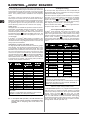
4. AUDIO ROUTING
The B-CONTROL gives you a plethora of routing options that are explained in detail in this chapter. The following illustration will give
you a general overview of your BCA2000s audio signal flow. You will find a detailed signal flow diagram on an extra sheet attached
to this manual.
Fig. 4.1: Block diagram (overview)
4.1 Input routing
Analog inputs:
The input selectors ( , , and ) let you select the
signal sources for the input channels. For the mono input channel,
you can select a microphone input (MIC A), the left line input
(Line L) or the front-panel high-impedance guitar input. If the
GUITAR (HI-Z) button is pressed, the MIC/LINE button is
deactivated; mic or line inputs can no longer be selected.
On the stereo input channel, you can select between a
microphone input B (MIC B) and the right line input (Line R).
The LINE STEREO button gives you yet another routing option,
directing both left and right line inputs ( ) into this channel,
which then operates as a stereo channel. In this case, the mono
input channel can no longer carry the left line signal. However,
you can still select a microphone or guitar signal, so that a total of
3 signals (1 x mono, 1 x stereo) can be recorded simultaneously.
4. AUDIO ROUTING
MIC B
Line R
Line Stereo
MIC B
Line R
Line Stereo
MIC B
Line R
Line Stereo
Line L
MIC A
GUITAR (HI-Z)
Table 4.1: Analog input combination options
Insert connections are available for all mono inputs (XLR and
¼" connectors). This insert point for external signal processors
is located directly before (pre-) the B-CONTROLs internal
processing and A/D converters. All selectable sources can be
processed in the mono input channel, while only inputs MIC B
and LINE R can be processed in the stereo input channel.

12
B-CONTROL AUDIO BCA2000
If LINE STEREO is selected and both insert connectors are in
use, only the right (LINE R) signal in the stereo input channel will
be processed via insert B. Insert A works only on the mono input
channel and is not affected by the position of the LINE STEREO
button. +48 V phantom power is available for the microphone
inputs.
The signals of both input channels are mixed together into a
stereo input sum and fed into the two-channel A/D converter.
Before this, the input sum signal can be processed by the internal
dynamics processing section of your B-CONTROL. In this case,
the signal first goes to the noise gate and then to the limiter
(which effectively protects the A/D converter from clipping).
Digital inputs:
The digital inputs are available as optical and coaxial connectors.
Both S/PDIF and AES/EBU formats are supported. The optical
input also accepts signals in ADAT
®
format. Four-channel
24-bit/96 kHz operation with ADAT
®
S/MUX is also possible. Use
the DIGITAL IN button to select the digital input source. The
selection is displayed in the audio routing diagram on the top of
your BCA2000.
If an ADAT
®
or an ADAT
®
S/MUX signal is connected to the
optical input, it is automatically recognized and activated, and the
red LED in the audio routing diagram illuminates. In this case, the
analog inputs are deactivated.
Combination of analog and digital inputs:
The High-Speed USB connection transmits a maximum of eight
input channels. This can either be an eight-channel ADAT
®
signal
or a combination of digital and analog input signals. Due to the
BCA2000s input architecture, these are the input sum signal
and a two-channel digital input signal. This signal can either
come from the optical or the coaxial input, and can be selected
using the DIGITAL IN switch . The digital format (AES/EBU or
S/PDIF) is selected in the control panel software. If an
ADAT
®
S/MUX stream is transmitted, a maximum of four channels
at 24 bit/96 kHz is available. The following table provides an
overview of the possible combinations:
1 Analog In Sum L ADAT In 1 S/MUX In 1
2 Analog In Sum R ADAT In 2 S/MUX In 2
3
Digital In L
2
ADAT In 3 S/MUX In 3
4
Digital In R
2
ADAT In 4 S/MUX In 4
5 - ADAT In 5 -
6 - ADAT In 6 -
7 - ADAT In 7 -
8 - ADAT In 8 -
1 Analog In Sum L ADAT In 1 -
2 Analog In Sum R ADAT In 2 -
3
Digital In L
2
ADAT In 3 -
4
Digital In R
2
ADAT In 4 -
High-Speed Mode (480 Mbit/s)
Full-Speed Mode (12 Mbit/s)
1) Optical digital input must be selected. Analog In Sum (inpu
t
sum) muted.
2) Optical or coaxial digital input selectable. Format selection
(AES/EBU or S/PDIF) via control panel software.
Table 4.2: Input routing
+ In Full-Speed USB operation, the USB interface can
only transmit 4 audio channels. Transmitting audio
signals with a sampling rate of 96 kHz is not
possible!
4.2 Output routing
On the output side, eight channels can also be transmitted via
(High-Speed) USB. Various combinations of analog and digital
outputs are available for playback.
The stereo input sum signal for USB transmission is created in
the mixer of your audio software. This signal is fed digitally
through the optical and coaxial outputs. The same
signal is also available on the main analog outputs. Additionally,
there are four analog RCA outputs that can be used for playing
back subgroups, monitor mixes or surround signals.
Use the OPTICAL OUT button to select a digital format for
the optical output: ADAT or 2-CHANNEL.
4.2.1 Output routing in ADAT mode
In ADAT
®
mode (OPTICAL OUT button not pressed), eight
channels can be played back in ADAT
®
format via the optical
output. The eight-channel signal is also available on the analog
outputs; signal/output assignments are shown in table 4.3. Use
the CH. 1-2/CH. 7-8 button to assign a signal source to the
coaxial output: either USB channel 1-2 or 7-8. The transmission
of 96-kHz signals is done per sample multiplexing via the ADAT
®
output.
1 Main Out 1/L
Digital L
1
ADAT Out 1 S/MUX Out
1
2 Main Out 2/R
Digital R
1
ADAT Out 2 S/MUX Out
2
3 Analog Out 3 - ADAT Out 3 S/MUX Out
3
4 Analog Out 4 - ADAT Out 4 S/MUX Out
4
5 Analog Out 5 - ADAT Out 5 -
6 Analog Out 6 - ADAT Out 6 -
7-
Digital L
1
ADAT Out 7 -
8-
Digital R
1
ADAT Out 8 -
Main Out 1/L ADAT Out 1
Analog Out 5 ADAT Out 5
Main Out 2/R ADAT Out 2
Analog Out 6 ADAT Out 6
ADAT Out 3
ADAT Out 7
ADAT Out 4
ADAT Out 8
3
4
Analog Out 3
Digital L
2
-
-
Digital R
2
Analog Out 4
High-Speed Mode (480 Mbit/s)
Full-Speed Mode (12 Mbit/s)
1) Sw itchable betw een USB Outs 1-2 and USB Outs 7-8
(High-Speed Mode) via button 23. Format selection (AES/EBU
or S/PDIF) via control panel software.
2) Switchable betw een USB Outs 1-2 and USB Outs 3-4 (Full-
Speed Mode) via button 23. Format selection (AES/EBU or
S/PDIF) via control panel software.
1
2
Digital L
2
Digital R
2
-
-
Table 4.3: Output routing in ADAT
®
mode
In Full-Speed USB operation, only 4 signals are transmitted per
USB, and there is no support for 96 kHz operation. The digital
coaxial output always carries one stereo signal selectable with
the CH. 1-2/CH. 7-8 button : when set to CH. 1-2, USB
channels 1 and 2 (Main Out Signal) are transmitted; when set to
CH. 7-8, USB channels 3 and 4 are transmitted. These signals
are simultaneously fed to analog outputs 3 and 4. On the ADAT
®
output, the four USB channels are doubly occupied to transmit
the eight ADAT channels (see table 4.3).
4. AUDIO ROUTING

13
B-CONTROL AUDIO BCA2000
4.2.2 Output routing in 2-CHANNEL mode
In two-channel operation (OPTICAL OUT button pressed), all six
analog outputs for USB channels 1 through 6 are available.
Simultaneously, the digital outputs are used for two additional
channels that are available at both the optical and the coaxial
outputs. You can select between channels 1 and 2 (Main Out) or
channels 7 and 8 via the CH. 1-2/CH. 7-8 button . The
transmission format in this mode can be S/PDIF, AES/EBU,
DOLBY
®
DIGITAL or DTS
®
, provided the respective format is
supported by the host software.
1 Main Out 1/L
Digital Out L
1
Digital Out L
1
2 Main Out 2/R
Digital Out R
1
Digital Out R
1
3 Analog Out 3 - -
4 Analog Out 4 - -
5 Analog Out 5 - -
6 Analog Out 6 - -
7-
Digital Out L
1
Digital Out L
1
8-
Digital Out R
1
Digital Out R
1
Main Out 1/L
Analog Out 5
Main Out 2/R
Analog Out 6
High-Speed Mode (480 Mbit/s)
Full-Speed Mode (12 Mbit/s)
Digital Out L
2
Digital Out R
2
-
-
1
2
2) Sw itchable betw een USB Outs 1-2 and USB Outs 3-4 (Full-
Speed Mode) via button 23. Format selection (AES/EBU or
S/PDIF) via control panel software.
1) Sw itchable betw een USB Outs 1-2 and USB Outs 7-8
(High-Speed Mode) via button 23. Format selection (AES/EBU
or S/PDIF) via control panel software.
3
4
Analog Out 3
Digital Out L
2
-
Analog Out 4
Digital Out R
2
-
Table 4.4: Output routing in two-channel mode
In Full-Speed USB operation, the USB outputs are not only
reproduced on the main outputs but also in parallel via analog
outputs 5 and 6. USB outputs 3 and 4 are routed to analog
outputs 3 and 4 and to both digital outputs, provided the CH. 1-2/
CH. 7-8 button is set to CH.7-8. When set to CH. 1-2,
output channels 1 and 2 are routed to the digital outputs. The
position of this button affects both digital outputs.
4.3 First steps with the B-CONTROL
Connections (see also application examples in ch. 5):
Make sure the B-CONTROL is off before connecting it to other
equipment. Connect your microphones to the XLR inputs. Amplified
instruments or other line-level equipment (keyboards, CD players,
external microphone preamplifiers etc.) are connected to the line
inputs. If you want to record an electric guitar or other high-
impedance instrument (e.g. acoustic instruments with passive
pickups), connect this instrument to the HI-Z input on the
B-CONTROLs front panel.
If you want to process your signal with external compressors,
equalizers, de-essers or the like before recording it, connect
these processors via the insert connections using commercially
available insert cables (see ch. 6.2).
Use the analog main outputs to connect a mastering recorder.
To stay in the digital domain during mastering, you can also
connect a digital recorder via the coaxial or optical outputs.
Connect your studio loudspeakers or their amplifiers to the control
room outputs.
4. AUDIO ROUTING
Recording:
Lets assume you want to record vocals: connect your
microphone to one of the two XLR microphone inputs. If youre
using a condenser microphone that requires phantom power,
press the +48 V button . Set the level by slowly turning the
TRIM control to the right while you (or your singer) speak(s)
or sing(s) into the microphone. Keep an eye on the input-signal
level display . An incoming signal is indicated via the SIGNAL
LED. The CLIP LED illuminates as soon as the input signals level
is too high and could possibly cause audible distortion. We
incorporated a bit of headroom here so that the LED illuminates a
few dBs before clipping/distortion. Adjust the trim control so that
the CLIP LED only occasionally illuminates during the loudest
passages. The input signal now has an optimal level. Use the
channel fader to adjust the recording volume. Be sure not to
overdrive the A/D converters by carefully observing the level
meter and adjusting levels if necessary. Press the METER
button to show the level of the input sum signal. Since the input
sum signal has no level control of its own, you will have to
control the master volume with both channel faders when
simultaneously recording several signals. Ideally, the CLIP LED
should never illuminate. Keep an eye on the correct input signal
level in your software. Activate the desired audio track in your
software and start recording by pressing the record button.
Noise Gate:
Use the noise gate to suppress hissing and other ambient noise
during signal pauses. Slowly turn the noise gate threshold control
clockwise until the noise has faded out; the microphone
should be on but the singer should not be singing. When turned
all the way to the left, the signal is not processed and the
THRESHOLD LED remains dark. As soon as the threshold value
exceeds the noise level and signal processing kicks in, the
THRESHOLD LED illuminates. Set the threshold value very
carefully so that vocal signals are not muted during fade-outs,
fade-ins or quiet passages. It may be necessary to fine-tune the
threshold setting with the vocalist singing (but not during the
recording!).
Limiter:
The limiter serves to limit the dynamics of the input signal. You
should always use the limiter if the level of the vocal varies
extremely while setting levels. Adjust the limiter so that it kicks in
briefly before maximum level. To this end, turn the LIMITER control
slowly from its off position (fully clockwise) counter-
clockwise until the LIMIT LED begins to illuminate during the loudest
signals.
Playback:
If you want to add tracks or vocals to an already recorded piece
(overdub), you will want to hear the recorded tracks while
overdubbing. The monitor section of the B-CONTROL offers
various options for this purpose. Generally, you will be listening
to the stereo sum signal of your software mixer. This signal is
routed to the main output and can be adjusted using the main
fader. It is also available at the headphone outputs and the
control room outputs .
DIRECT monitoring:
During a recording, you probably not only want to hear the
playback, but also the sound of what you are singing or playing.
In AUTO monitoring mode (MONITOR button not pressed),
your audio software automatically switches between input and
playback signals, i.e., as soon as you start recording in your
software, you can hear the input signal being recorded. When you
switch to playback, you will only hear your recorded audio tracks.
In AUTO mode, system-specific latency times occur between
the input signal and its playback from the computer. To avoid
this, you can switch to DIRECT monitoring mode before a
recording. This routes the input sum (pre-A/D converter) directly
to the control room and headphone outputs for monitoring.
The signal remains in the analog section of the B-CONTROL while
recording, resulting in latency-free monitoring. The mix between
the input signal and the playback signal from your computer can
be adjusted using the MONITOR BALANCE control .

14
B-CONTROL AUDIO BCA2000
ASIO Direct Monitoring:
For recording and playback purposes, the monitor signal can
also be switched in the software (the BCA2000 must be in
AUTO monitoring mode), provided your audio software supports
ASIO Direct Monitoring. For that purpose, the following settings
are available in the control panel software:
If you select Digital, the audio software switches the monitor
outputs of your B-CONTROL between the analog input sum
(record) and the main output signal (play); this depends on
whether the software is in recording or playback mode.
If Analog is selected, the monitor balance control is active during
a recording, and you can adjust the ratio between the playback
and input signals. During playback only the stereo mix from the
software is audible.
5. APPLICATIONS
5.1 Mobile studio
Fig. 5.1: Mobile studio
Even if you work almost exclusively with software, you still
need MIDI and audio interfaces to play your software synths via
a MIDI keyboard and record and listen to your music. The first
example shows a small setup for a mobile studio using the
BCA2000 as such an interface.
Connect the BCA2000 to a free USB port on your computer/
laptop. An older Full-Speed (1.1) USB interface will suffice unless
you want to work at 24-bit/96 kHz (see also 1.2.1 and 1.2.2).
You can play your software instruments live and/or record MIDI
tracks via the MIDI keyboard connected to the MIDI input. Monitoring
is achieved via headphones connected to one of the phones
outputs on the front panel of your BCA2000, while the volume is
adjusted using the corresponding PHONES control. Of course,
you can connect a second set of separately adjustable
headphones.
5. APPLICATIONS
Fig. 5.2: Extended mobile studio
In this illustration, we have augmented the first example with a
microphone and a MIDI expander. To record acoustic instruments
or vocals in your audio software, connect your microphones
directly to the XLR inputs. If youre using condenser microphones,
activate the +48 V phantom power. To record an electric guitar
or acoustic instrument with passive pickups, connect it to the
high-impedance guitar input located on the front panel.
Use the internal noise gate and compressor in your B-CONTROL
to process analog signals prior to A/D conversion. You can also
connect an external processor to the INSERT connectors
for signal processing using your favorite outboard gear.
The MIDI sound module is controlled via MIDI output A. The sound
module can be a GM/GS/XG MIDI expander, a synthesizer, a
sampler, a drum machine or other MIDI sound source. The audio
outputs can be routed to the software mixer via the analog
stereo line inputsor alternatively via the digital inputs, provided
the sound module you are using has digital outputs.
Listening during a recording session (monitoring) can be done
either digitally via the computer or latency-free using the direct
monitoring function of your BCA2000. The latter is extremely
helpful if the latency (computer-induced delay) is too high to
allow comfortable, accurate monitoring for performing musicians/
singers.

15
B-CONTROL AUDIO BCA2000
5. APPLICATIONS
5.2 Project studio
Fig. 5.3: Project studio
This application example shows the layout of a typical small
project studio in which both software and hardware sound
generators are used. The major difference between this and the
previous examples is the greatly expanded MIDI setup. The
BCA2000 acts as a central link between your studio equipment
and your computer.
The illustrated MIDI connections allow the full gamut of MIDI
functions to be utilized. Data from the MIDI controller and the MIDI
keyboard are fed into the computer via the MIDI input. To this end,
a MIDI keyboard and the two BEHRINGER MIDI controllers BCF2000
and BCR2000 are connected in series. MIDI performance data
are sent to the sequencer via the keyboard. Any signal-
processing plug-ins as well as the software mixer are controlled
by the two MIDI controllers.
The computer communicates separately with each MIDI expander
(in this case: a sound module and a sampler) via 16 MIDI channels
each.
The Audio wiring also represents an expansion of the setup
shown in fig. 5.2: the microphone and sound module signals are
mixed together in stereo in the BCA2000 before they pass through
the A/D converter. Additionally, an extra sound generator, stereo
player, effects unit or hardware sampler (as shown in the
illustration) can be fed into the computer via one of the two digital
inputs on the BCA2000. This four-channel signal (A/D-converted
stereo input sum + digital stereo signal) is simultaneously
transmitted to the computer via USB. This setup will also work
fine without a High-Speed USB connection, as long as you are
satisfied with a maximum sample rate of 48 kHz.
A pair of active studio monitors was added for monitoring,
connected to the control room outputs. Of course, two sets of
headphones can still be connected and be controlled separately
from the control room signal. You can adjust the monitor signal in
several different ways (mute, dim, mono function, monitor in/out
balance control etc.).

16
B-CONTROL AUDIO BCA2000
5.3 Professional studio
Fig. 5.4: Configuration of a professional studio
5. APPLICATIONS
This is a professional-style studio setup with much more external
equipment than in the previous examples. The MIDI network is
also expanded; the entire studios MIDI equipment is connected
to a central MIDI patchbay, which in turn is connected to the
BCA2000. The audio inputs are augmented via an analog mixing
console that submixes all sound sources (microphones,
keyboards, sound modules, samplers etc.) and feeds them into
the B-CONTROL as a stereo sum signal.
The MIDI equipment includes a MIDI keyboard and the two
BEHRINGER MIDI controllers BCF2000 and BCR2000 as input
devices. Similarly, the sampler and sound module A as well all
MIDI-capable effects processors (here: ULTRACURVE PRO
DEQ2496, V-VERB PRO REV2496 and VIRTUALIZER PRO
DSP2024P) are all connected to the MIDI patchbay. The patchbay
is connected to the BCA2000 via MIDI IN and MIDI OUT A, which
in turn transmits the entire studios MIDI data through a maximum
of 16 MIDI channels to your computer. Using the second MIDI
output of your BCA2000 (OUT B), you can address additional
MIDI devices using up to 16 additional MIDI channels.
The Audio wiring follows a submixing scheme: all microphones,
sound modules, effects processors and other gear such as
CD players, drum computers etc. are connected to an analog
mixing console (here: BEHRINGER EURODESK SL3242FX-PRO).
The stereo sum signal from the mixer is fed into the line inputs of
your BCA2000.

17
B-CONTROL AUDIO BCA2000
5. APPLICATIONS
Alternatively, you can use a digital mixing console, whose
digital stereo sum signal is routed to the computer via the digital
inputs on the B-CONTROL. If your digital console features an
ADAT
®
optical output (like the BEHRINGER DDX3216 with the
ADT1616 option), you can even transmit an eight-channel digital
signal, provided your computer supports High-Speed USB.
In our example with an analog mixer, a DAT or a CD recorder is
connected to the digital connectors. Along with the analog stereo
sum signal from the console, four parallel input channels are
transferred to the computer.
The Monitoring options are also considerably expanded in
this setup; all options can be used simultaneously. A pair of
BEHRINGER TRUTH B2030A active monitors with an additional
active subwoofer are used here as main monitors. The control
room outputs are connected to the subwoofer; from there the
signal is passed on to the TRUTH loudspeakers.
The same signal is also available via two sets of headphones
(e.g. for musicians), whereby their volume can be adjusted
separately.
An additional pair of monitor speakers is connected to the main
outputs. The new BEHRINGER MS16 speakers that simulate the
listening experience of using smaller monitors are shown here.
Their volume is adjusted using the main fader. With such flexible
control options, you can better judge the various criteria of your
mix in order to produce sonically accurate mixes that translate
well to various systems.
5.4 Basis recording session
Fig. 5.5: Basis recording session

18
B-CONTROL AUDIO BCA2000
5. APPLICATIONS
This recording setup is easily transportable, for example, to a
recording session at a friends or fellow musicians apartment.
All you need is a laptop computer, the BCA2000, two to three
headphones and/or a couple of active loudspeakersplus of
course microphones and instruments as required.
There are several options for recording a guitar: you can either
connect the guitar to the front-panel guitar input and process the
signal with the BCA2000s dynamics section and/or your
computers plug-ins or, as shown in the illustration on the previous
page, connect your guitar to a preamp (e.g. BEHRINGER V-AMP 2)
and the preamp to the BCA2000s line input.
Connect a vocal microphone to the MIC B input. You can also
record an acoustic guitar or other acoustic instruments together
with the vocals. In this case, use two microphones: one for the
instruments and the other one for the vocals.
If you are using loudspeakers for monitoring, the sound
engineerarmed with a laptop, the monitors and the BCA2000
should be located in a separate room isolated from the musicians,
in order to properly judge the recording without hearing the original
sound, and to prevent feedback and ambient noise problems.
If the engineer uses a third set of headphones instead of the
monitors, everyone can be in the same room (although the
engineer will have to be very quiet!). In this case, the two sets of
headphones for the musicians can be connected to one PHONES
output using a Y-cable or adapter. The sound engineers
headphones are then connected to the other PHONES connector.
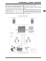
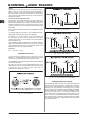
5.5 Multi-channel recording with
5.1 surround monitoring
Illustration 5.6 shows how to do a multi-channel recording of a
live performance and monitor it in 5.1 surround sound.
Theoretically, you can record an entire orchestra, big band, choir
or a play with a maximum of eight channels and monitor your
recording in 5.1 surround.
Recording: In our example, an orchestral performance is being
recorded. Six microphones are being used: 5 studio condenser
microphones and a so-called boundary microphone, which is
placed on the floor close to the orchestra. Of course, you can
also use other microphones and positioning as your experience
and/or preferences dictate.
Two microphones are used as main stereo mics (L/R), while a
third, emphasizing the center signal, is placed near the conductor.
Two additional microphones (facing the audience) record the
surround sound (surround left and surround right), while the
boundary microphone in the orchestra supports the low
frequencies for the LFE or sub-bass channel.
All microphone signals pass through a multi-channel mic preamp
and are converted into digital signals. The BEHRINGER
ULTRAGAIN PRO-8 DIGITAL ADA8000, shown here, generates
an eight-track ADAT
®
signal that is routed to the BCA2000 through
the optical output. From there on, it is passed on to the computer
via High-Speed USB.
Mix: To mix the live recording, hardware control elements to
control the software mixer can be very useful. In this illustration,
two BCF2000 MIDI controllers are used; connected to the
BCA2000 via MIDI, they control the software mixer during
recording/playback.
Monitoring/playback: All loudspeakers necessary for
5.1 surround monitoring can be connected directly to the
BCA2000s analog outputs. Here, 5 active monitor loudspeakers
(shown: BEHRINGER TRUTH B2030A) and a subwoofer for the
LFE channel are used. You can also connect two additional
loudspeakers to the control room outputs, with which you can
monitor the main stereo signal. The main stereo signal is also fed
to both headphone outputs, allowing conductors, technical
assistants or sound engineers to monitor via headphones.
The loudspeaker setup shown here can also be used to listen to
the sound track from a DVD playing on your computer in surround
sound, provided your software features a DOLBY
®
DIGITAL or
DTS
®
decoder.

19
B-CONTROL AUDIO BCA2000
5. APPLICATIONS
Fig. 5.6: Multi-channel recording with 5.1 surround monitoring

20
B-CONTROL AUDIO BCA2000
6. CONNECTIONS AND FORMATS
6.1 Glossary
Some technical terminology and acronyms that you may encounter
while working with the BCA2000 are explained in this glossary.
Explanations of additional terminology can be found in our online
glossary at www.behringer.com. You can find more information
about surround sound in the surround manual of our digital mixing
console DDX3216, which can be downloaded from our website
free of charge at www.behringer.com.
AC-3
More widely known as ® DOLBY
®
DIGITAL, AC-3 is the most
popular surround format today. Six separate digital sound
channels are data-compressed, encoded and ® decoded
(front left, front right, front middle/center, rear left, rear right and
sub-bass channel, called ® LFE).
The BCA2000 can reproduce this data format through the digital
outputs, provided your audio software contains a DOLBY
®
DIGITAL ® decoder. This can be an audio application that uses
a software decoder as a ® Plug-In or a DVD disc that is
reproduced on your computers DVD drive.
The six-channel music signal is then AC-3-encoded
(® Encoder), connected to a surround receiver with a digital
input (or similar) via one of the digital outputs and decoded
internally by the receivers AC-3 ® Decoder, and then reproduced
on the six analog speaker outputs.
ADAT
®
The eight-channel digital audio format ADAT
®
owes its name to
the first 8-track digital recorder from Alesis. The ADAT
®
format
has established itself as the multi-channel standard of choice,
generally supporting 44.1 and 48 kHz ® Sample Rates.
88.2 and 96 kHz sample rates are also possible, but only with
four (instead of eight) digitally transmitted channels. This version
is called ® S/MUX.
Just a single optical cable (very thin optical fiber) is required to
transmit all eight (or four) channels of an ADAT
®
signal between
two different units using the optical input and output connectors.
These connectors are sometimes called ® TOSLINK.
The BCA2000 supports both the standard ADAT
®
format with 8
channels (at 44.1 or 48 kHz sampling rate) and the S/MUX format
with 4 channels (at 96 kHz sampling rate), both on the inputs and
the outputs via the optical in/out connectors.
A/D converter
An A/D converter transforms an analog audio signal into a digital
signal, for example to enable recording on digital recorders such
as CD/DAT/MD recorders or for recording and/or additional
processing in a computer.
All equipment utilizing digital technology that features standard
analog connectors (i.e. 1/4" or XLR) has an internal A/D ® D/A
Converter. These can be synthesizers, digital mixing consoles,
almost all standard delay or multi-effects units or sound cards.
The quality of the converter is often expressed as a combination
of its bit rate and its sampling frequency (e.g. 24-bit/96 kHz).
Generally speaking, the higher these two values, the better the
resolution and therefore the better the audio quality. Older
CD players operate at 16-bit/44.1 kHz. The BCA2000 supports
the current DVD quality standard of 24-bit/96 kHz.
AES/EBU
This professional digital stereo audio format gets its acronym
from the Audio Engineering Society and European Broadcasting
Union. Unlike the consumer format ® S/PDIF, AES/EBU signals
are usually transmitted using balanced cables with XLR
connectors, enabling extremely long cable runs without signal
degradation or additional noise. See also ® S/PDIF.
Clock
Many digital devices feature ® Sync, Clock or Wordclock
connections, usually in the form of coaxial BNC connectors.
When using two or more interconnected digital devices
simultaneously, they must be synchronized to the same clock to
ensure sample rate timing coherence. This synchronization is
performed via the wordclock connector or the digital inputs, i.e.
through the digital audio signal.
Coder/Coding
Synonymous to ® Encoder/Encoding.
D/A converter
A D/A converter converts digital audio signals into analog audio
signals. See also ® A/D Converter.
Decoder/Decoding
Decoding refers to deciphering a digital signal. If you wish to
transmit or store a digital signal in compressed form (condense/
reduce data quantity), you will have to ® encode it. To use this
signal later or at a different location, you will have to first decode
the signal. These processes generally occur automatically in
digital audio devices/applications.
DOLBY
®
DIGITAL
A more popular name for the ® AC-3 surround format.
DTS
®
The Digital Theater Sound System is similar in function to the 6-
channel surround format ® DOLBY
®
DIGITAL (® AC-3).
Because DTS
®
utilizes more moderate compression (data
reduction), it sounds somewhat better than AC-3 but requires
more storage space, e.g. on a DVD. This format is also supported
by the BCA2000 on its digital outputs.
Encoder/Encoding
Encoding refers to encrypting a digital signal using an encoder.
See ® Decoder/Decoding.
Interface
General term referring to connection standards used for digital
data transfer.
The ® MIDI interface enables communication between digital
devices; a device with a MIDI interface generally has three MIDI
connectors: MIDI In, Out and Thru. The BCA2000 has all three.
Audio interface generally refers to both internal and external
computer sound cards. Internal are those that are built into the
computer (usually PCI cards). External sound cards or audio
interfaces are those that are usually connected to the computer
via ® USB or IEE1394 (also known as FireWire
®
), such as the
BCA2000.
LFE
LFE (Low Frequency Effect; sometimes called Low Frequency
Enhanced) refers to the ® Subwoofer or sub-bass channel that
reproduces the lowest frequencies of the surround soundtrack
(generally below 80 Hz). This ultra low-frequency information is
usually experienced as sound pressure rather than as identifiable
audio, especially in movie theaters. Even when the
LFE-subwoofer is located front and center, the signal is hard to
locate spatially, since frequencies this low are difficult for the
human ear to process preciselyso instead of actually hearing
them, you feel them. The .1 in the nomenclature of various
surround formats, such as 5.1, 6.1 and 7.1, refers to the LFE
channel. See also ® Surround.
Limiter
A limiter limits the dynamic spectrum of signal peaks. The maximal
volume of a signal is defined by the ® Threshold value.
Limiters are often used to avoid overdriving ® A/D Converters,
because this can cause digital distortion, whichunlike slight
analog distortionis extremely unpleasant, clearly audible and
never desirable. The BCA2000 features an adjustable limiter for
the input sum directly pre- (before) ® A/D Converters.
6. CONNECTIONS AND FORMATS
Page is loading ...
Page is loading ...
Page is loading ...
Page is loading ...
-
 1
1
-
 2
2
-
 3
3
-
 4
4
-
 5
5
-
 6
6
-
 7
7
-
 8
8
-
 9
9
-
 10
10
-
 11
11
-
 12
12
-
 13
13
-
 14
14
-
 15
15
-
 16
16
-
 17
17
-
 18
18
-
 19
19
-
 20
20
-
 21
21
-
 22
22
-
 23
23
-
 24
24


Behringer BCA2000 User manual
- Category
- Musical Instruments
- Type
- User manual
- This manual is also suitable for
Ask a question and I''ll find the answer in the document
Finding information in a document is now easier with AI
Related papers
-
Behringer U-CONTROL UCA200 Operating instructions
-
-
-
Behringer B-CONTROL ROTARY BCR2000 User manual
-
Behringer C-1U User manual
-
-
-
-
Behringer B-CONTROL ROTARY BCR2000 User manual
-
Other documents
-
Midiplus miniEngine USB Installation guide
-
Value Audio Converter - Digital to Analogue User manual
-
Orei DA21 User manual
-
 Presonus Audio electronic D8 User manual
-
Art Tube MP PS Owner's manual
-
-
PRESONUS FireStudio Owner's manual
-
Tascam FW-1804 Owner's manual
-
Focusrite Scarlett 18i8 User manual
-
Edirol UA-1000 Owner's manual
