
Manual Insert
PHONE: (360) 734-1540 • www.southbendlathe.com
MODEL SB1050F HEAVY-13
13" X 40" GEARHEAD LATHE w/DRO
Copyright © December, 2013 by South Bend Lathe Co.
WARNING: No portion of this manual may be reproduced without written approval.
#TS16217 Printed in Taiwan
The Model SB1050F Lathe is the same machine as the Model SB1050 except for the following:
• Added a 2-Axis Fagor Digital Readout (DRO).
Except for the differences noted in this insert, all other content in the Model SB1050 Owner’s Manual
applies to this machine. Before operating your new lathe, you MUST read and understand this insert,
the entire Model SB1050 Owner’s Manual, and the Fagor DRO Owner’s Manual to reduce the risk of
injury when using this machine. Keep this insert for later reference.
If you have any further questions about this manual insert or the differences between the Model
SB1050F and the Model SB1050, contact our Technical Support at (360) 734-1540 or email
REF PART # DESCRIPTION REF PART # DESCRIPTION
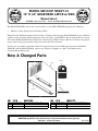
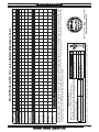
1570 PSB1050F1570 DRO ASSEMBLY FAGOR 2-AXIS 1570-3 PSB1050F1570-3 DRO Y-AXIS SCALE FAGOR MKT-27
1570-1 PSB1050F1570-1 DRO DISPLAY FAGOR 20-iT 1615 PSB1050F1615 MACHINE ID LABEL
1570-2 PSB1050F1570-2 DRO X-AXIS SCALE FAGOR MKT-102 1620 PSB1050F1620 MODEL NUMBER BRASS PLATE
New & Changed Parts
1620
1615
1570
1570-1
1570-3
1570-2
Motor: 3 HP, 220V, 1-Ph, 60 Hz
Full-Load Current Rating: 19.45A
Swing Over Bed: 13.38"
Distance Between Centers: 40"
Swing Over Cross Slide: 8.26"
Swing Over Gap: 20"
Cross Slide Travel: 7"
Made in Taiwan to South Bend Specifications
MODEL SB1050F
HEAVY 13
®
13" x 40"
GEARHEAD LATHE w/DRO
MFG Date
Serial No.
®
Compound Travel: 4"
Spindle Nose: D1-5 Camlock
Spindle Bore: 1.57"
Spindle Taper: MT#5
Tailstock Taper: MT#3
Weight: 2227 lbs.
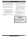
WARNING!
!
To reduce the risk of serious personal injury while using this machine:
1. Read and understand owner’s manual before starting.
2. Always wear approved safety glasses AND a face shield.
3. Properly ground machine—connect to permanently grounded metal
wiring system or an equipment-grounding conductor.
4. Tie back long hair, roll up sleeves, and DO NOT wear loose clothing,
gloves, or jewelry.
5. Disconnect power before setting up, adjusting, or servicing.
6. Rotate workpiece by hand to ensure clearance before starting.
7. Test each new workpiece setup for safe rotation; start with slowest
speed and stand to side of lathe until safe rotation verified.
8. Keep all guards and covers in place during operation.
9. Change coolant regularly and avoid contact with skin.
10. Never leave chuck key in chuck.
11. Never leave lathe running unattended.
12. DO NOT reverse spindle rotation while spindle is moving.
13. Proper ly support long workpieces with an appropriate r est.
14. DO NOT expose to rain or use in wet locations.
15. Pr event unauthorized use by childr en or untrained users.
SB1050F
V1.12.13

Model SB1050F
Page 1 of 4
Model SB1050F
Heavy 13 - 13" x 40" Gearhead Lathe with
Fagor DRO
Product Dimensions
Weight........................................................................................................................................................... 2227 lbs.
Width (side-to-side) x Depth (front-to-back) x Height.....................................................................
90 x 38 x 69 in.
Footprint (Length x Width)...........................................................................................................
80-3/4 x 19-1/2 in.
Shipping Dimensions
Type.......................................................................................................................................................... Wood Crate
Content.......................................................................................................................................................... Machine
Weight........................................................................................................................................................... 2645 lbs.
Length x Width x Height.................................................................................................................
71 x 90 x 45 lbs.
Electrical
Power Requirement.........................................................................................................
220V, Single-Phase, 60 Hz
Full-Load Current Rating............................................................................................................................... 19.45A
Minimum Circuit Size.......................................................................................................................................... 30A
Connection Type..................................................................................................................................... Cord & Plug
Power Cord Included..............................................................................................................................................
No
Recommended Power Cord.............................................................................
"S"-Type, 3-Wire, 12 AWG, 300 VAC
Plug Included.......................................................................................................................................................... No
Recommended Plug Type.................................................................................................................................. L6-30
Switch Type....................................................................................... Control Panel w/Magnetic Switch Protection
Motors
Main
Type.............................................................................................................
TEFC Capacitor-Start Induction
Horsepower...............................................................................................................................................
3 HP
Phase............................................................................................................................................ Single-Phase
Amps........................................................................................................................................................... 19A
Speed................................................................................................................................................ 1725 RPM
Power Transfer ............................................................................................................................
V-Belt Drive
Bearings................................................................................................
Shielded & Permanently Lubricated
Coolant Pump
Type............................................................................................. TEFC Capacitor-Start Induction (Class F)
Horsepower............................................................................................................................................ 1/8 HP
Phase............................................................................................................................................ Single-Phase
Amps........................................................................................................................................................
0.45A
Speed................................................................................................................................................
3450 RPM
Power Transfer ............................................................................................................................ Direct Drive
Bearings................................................................................................ Shielded & Permanently Lubricated
-2-
Mfd. Since 12/13
Model SB1050F
MANUAL INSERT

Model SB1050F
Page 2 of 4
Main Specifications
Operation Info
Swing Over Bed.................................................................................................................................. 13.38 in.
Distance Between Centers...................................................................................................................... 40 in.
Max Weight Between Centers.............................................................................................................
440 lbs.
Swing Over Cross Slide........................................................................................................................
8.26 in.
Swing Over Saddle............................................................................................................................. 11.02 in.
Swing Over Gap....................................................................................................................................... 20 in.
Maximum Tool Bit Size.......................................................................................................................... 3/4 in.
Compound Travel......................................................................................................................................
4 in.
Carriage Travel..................................................................................................................................
36-1/2 in.
Cross Slide Travel...................................................................................................................................... 7 in.
Headstock Info
Spindle Bore.......................................................................................................................................... 1.57 in.
Spindle Taper.......................................................................................................................................... MT#5
Number of Spindle Speeds..............................................................................................................................
8
Spindle Speeds.........................................................................................................................
80 – 2000 RPM
Spindle Type.............................................................................................................................. D1-5 Camlock
Spindle Bearings...................................................................................................................... Tapered Roller
Spindle Length.................................................................................................................................. 20-7/8 in.
Spindle Length with 3-Jaw Chuck.........................................................................................................
27 in.
Spindle Length with 4-Jaw Chuck.........................................................................................................
25 in.
Spindle Length with Faceplate......................................................................................................... 22-1/2 in.
Tailstock Info
Tailstock Quill Travel.......................................................................................................................... 4-1/2 in.
Tailstock Taper........................................................................................................................................ MT#3
Tailstock Barrel Diameter..................................................................................................................
1.968 in.
Threading Info
Number of Longitudinal Feeds.....................................................................................................................
17
Range of Longitudinal Feeds......................................................................................... 0.002 – 0.067 in./rev.
Number of Cross Feeds................................................................................................................................. 17
Range of Cross Feeds..................................................................................................... 0.001 – 0.034 in./rev.
Number of Inch Threads...............................................................................................................................
45
Range of Inch Threads.....................................................................................................................
2 – 72 TPI
Number of Metric Threads........................................................................................................................... 39
Range of Metric Threads........................................................................................................... 0.2 – 14.0 mm
Number of Modular Pitches.......................................................................................................................... 18
Range of Modular Pitches............................................................................................................
0.3 – 3.5 MP
Number of Diametral Pitches.......................................................................................................................
21
Range of Diametral Pitches.............................................................................................................. 8 – 44 DP
Dimensions
Bed Width.................................................................................................................................................. 9 in.
Leadscrew Diameter............................................................................................................................ 1-1/8 in.
Leadscrew TPI.........................................................................................................................................
4 TPI
Leadscrew Length....................................................................................................................................
59 in.
Steady Rest Capacity............................................................................................................. 5/16 – 4-5/16 in.
Follow Rest Capacity.................................................................................................................. 5/8 – 3-1/8 in.
Faceplate Size.......................................................................................................................................... 10 in.
Feed Rod Diameter.................................................................................................................................
3/4 in.
Floor to Center Height......................................................................................................................
42-1/4 in.
Height With Leveling Jacks.................................................................................................................... 59 in.
Mfd. Since 12/13 Model SB1050F
-3-
MANUAL INSERT

Model SB1050F
Page 3 of 4
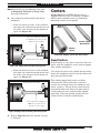
Construction
Base.................................................................................................................................................... Cast Iron
Headstock.......................................................................................................................................... Cast Iron
End Gears....................................................................................................................
Flame Hardened Steel
Bed.................................................................
Induction-Hardened, Precision-Ground Meehanite Cast Iron
Body................................................................................................................................................... Cast Iron
Stand.................................................................................................................................................. Cast Iron
Paint................................................................................................................................................... Urethane
Fluid Capacities
Headstock Capacity................................................................................................................................
6.4 qt.
Headstock Fluid Type...........................................................
ISO 32 (eg. Grizzly T23963, Mobil DTE Light)
Gearbox Capacity.................................................................................................................................... 1.4 qt.
Gearbox Fluid Type.................................................................. ISO 68 (eg. Grizzly T23962, Mobil Vactra 2)
Apron Capacity....................................................................................................................................... 1.2 qt.
Apron Fluid Type.....................................................................
ISO 68 (eg. Grizzly T23962, Mobil Vactra 2)
Coolant Capacity...................................................................................................................................
11.1 qt.
Other
Country Of Origin .......................................................................................................................................... Taiwan
Warranty ......................................................................................................................................................... 1 Year
Approximate Assembly & Setup Time .......................................................................................................... 1 Hour
Serial Number Location ................................................................................. ID Label on Rear Side of Left Stand
Sound Rating .................................................................................................................................................... 71 dB
ISO 9001 Factory ................................................................................................................................................... No
CSA Certified ......................................................................................................................................................... No
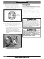
Features
Allen Bradley Electrical Components
Signature South Bend 3 V-Way Bed
Safety Chuck Guard with Micro-Switch Shut-Off
Meehanite Castings with Induction-Hardened Ways
Halogen Work Light
4-Way Tool Post
Complete Coolant System
Micrometer Carriage Stop
Threading Dial Indicator
NSK or NTN Japanese Spindle Bearings
Full Length Splash Guard
Front Removable Sliding Chip Tray
Completely Enclosed Universal Gearbox for Cutting Inch, Metric, Modular and Diametral Pitches
Jog Button and Emergency Stop
Foot Brake
Headstock Gears Run in an Oil Bath
Fagor DRO
-4-
Mfd. Since 12/13
Model SB1050F
MANUAL INSERT

© January, 2012 by South Bend Lathe Co. For Machines Mfg. Since 5/11
13" HEAVY 13
®
GEARHEAD LATHE
MODEL SB1049 13" X 30"
MODEL SB1050 13" X 40"
OWNER'S MANUAL

Customer Service
We stand behind our machines. If you have any service questions, parts requests or general questions
about your purchase, feel free to contact us.
South Bend Lathe Co.
P.O. Box 2027
Bellingham, WA 98227
Phone: (360) 734-1540
Fax: (360) 676-1075 (International)
Fax: (360) 734-1639 (USA Only)
Email: [email protected]
Updates
For your convenience, any updates to this manual will be available to download free of charge
through our website at:
www.southbendlathe.com
Scope of Manual
This manual helps the reader understand the machine, how to prepare it for operation, how to control
it during operation, and how to keep it in good working condition. We assume the reader has a basic
understanding of how to operate this type of machine, but that the reader is not familiar with the
controls and adjustments of this specific model. As with all machinery of this nature, learning the
nuances of operation is a process that happens through training and experience. If you are not an
experienced operator of this type of machinery, read through this entire manual, then learn more
from an experienced operator, schooling, or research before attempting operations. Following this
advice will help you avoid serious personal injury and get the best results from your work.
Manual Feedback
We've made every effort to be accurate when documenting this machine. However, errors sometimes
happen or the machine design changes after the documentation process—so
the manual may not
exactly match your machine.
If a difference between the manual and machine leaves you in doubt,
contact our
customer service for clarification.
We highly value customer feedback on our manuals. If you have a moment, please share your
experience using this manual. What did you like about it? Is there anything you would change to
make it better? Did it meet your expectations for clarity, professionalism, and ease-of-use?
South Bend Lathe, Inc.
C
/O Technical Documentation Manager

Table of Contents
INTRODUCTION ....................................................3
About This Machine .............................................3
Foreword ............................................................. 3
Capabilities .........................................................3
Features ..............................................................3
General Identification ..........................................4
Controls & Components.......................................5
Master Power Switch ........................................... 5
Headstock ...........................................................5
Control Panel ......................................................6
Carriage .............................................................. 6
Tailstock .............................................................7
End Gears ...........................................................7
Safety Foot Brake ................................................ 7
Product Specifications .........................................8
SAFETY ................................................................12
Understanding Risks of Machinery ..................12
Basic Machine Safety ........................................12
Additional Metal Lathe Safety ..........................14
Additional Chuck Safety....................................15
PREPARATION ....................................................16
Preparation Overview ........................................16
Things You'll Need .............................................16
Power Supply Requirements ............................. 17
Availability ........................................................17
Full-Load Current Rating ..................................17
Circuit Requirements .........................................17
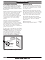
Grounding Requirements ...................................18
Extension Cords ................................................18
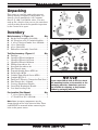
Unpacking ..........................................................19
Inventory ............................................................19
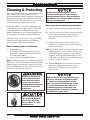
Cleaning & Protecting .......................................20
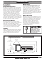
Location ..............................................................21
Physical Environment ........................................21
Electrical Installation ........................................21
Lighting ............................................................21
Weight Load ...................................................... 21
Space Allocation ................................................21
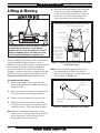
Lifting & Moving ................................................22
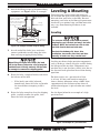
Leveling & Mounting .........................................23
Leveling ............................................................23
Bolting to Concrete Floors ..................................24
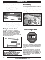
Assembly ............................................................24
Lubricating Lathe .............................................. 24
Adding Coolant ..................................................25
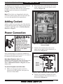
Power Connection ..............................................25
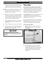
Test Run .............................................................26
Spindle Break-In ................................................30
Recommended Adjustments .............................. 30
OPERATION ........................................................31
Operation Overview ...........................................31
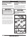
Chuck & Faceplate Mounting ...........................32
Installation & Removal Devices ........................32
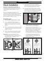
Chuck Installation .............................................33
Registration Marks ............................................34
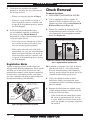
Chuck Removal ..................................................34
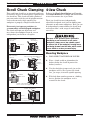
Scroll Chuck Clamping ......................................35
4-Jaw Chuck .......................................................35
Mounting Workpiece ..........................................35
Faceplate ............................................................36
Tailstock .............................................................37
Positioning Tailstock .........................................37
Using Quill ........................................................37
Installing Tooling ..............................................38
Removing Tooling ..............................................39
Offsetting Tailstock ...........................................39
Aligning Tailstock to Spindle Centerline ............40
Centers ...............................................................41
Dead Centers .....................................................41
Live Centers ...................................................... 42
Mounting Dead Center in Spindle ......................42
Removing Center from Spindle ...........................42
Mounting Center in Tailstock .............................42
Removing Center from Tailstock ........................43
Mounting Workpiece Between Centers ............... 43
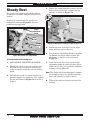
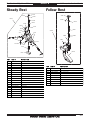
Steady Rest ........................................................44
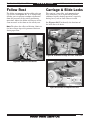
Follow Rest .........................................................45
Carriage & Slide Locks ......................................45
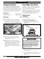
Compound Rest .................................................. 46
Four-Way Tool Post ...........................................46
Installing Tool ...................................................46
Aligning Cutting Tool with Spindle Centerline ...47
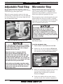
Adjustable Feed Stop .........................................48
Micrometer Stop.................................................48
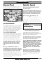
Manual Feed ......................................................49
Carriage Handwheel ..........................................49
Cross Slide Handwheel ......................................49
Compound Rest Handwheel ...............................49
Spindle Speed .....................................................49
Determining Spindle Speed ................................49

Setting Spindle Speed ........................................50
Configuration Examples .....................................50
Power Feed ......................................................... 51
Power Feed Controls ..........................................52
Setting Power Feed Rate ....................................53
End Gears ...........................................................54
Standard End Gear Configuration ......................54
Alternate Configuration ..................................... 55
Threading ...........................................................56
Headstock Threading Controls ........................... 56
Apron Threading Controls..................................57
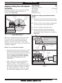
Thread Dial ....................................................... 57
Thread Dial Chart .............................................58
Chip Drawer .......................................................59
Coolant System ..................................................60
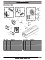
ACCESSORIES ...................................................61
MAINTENANCE ...................................................64
Maintenance Schedule .......................................64
Cleaning & Protecting .......................................64
Maintenance Chart ............................................65
Lubrication ......................................................... 66
Headstock .........................................................66
Quick-Change Gearbox ......................................67
Apron ................................................................ 67
One-Shot Oiler ..................................................68
Longitudinal Leadscrew .....................................68
Ball Oilers & Oil Cup .........................................69
End Gears .........................................................70
Coolant System Service .....................................71
Hazards.............................................................71
Adding Fluid .....................................................72
Changing Coolant .............................................. 72
Machine Storage ................................................73
SERVICE .............................................................. 74
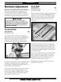
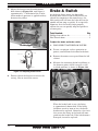
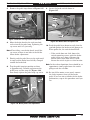
Backlash Adjustment ........................................74
Compound Rest .................................................74
Cross Slide ........................................................74
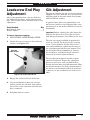
Leadscrew End Play Adjustment ......................75
Gib Adjustment ..................................................75
Half Nut Adjustment ......................................... 77
V-Belts ................................................................ 77
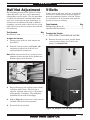
Brake & Switch .................................................. 78
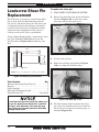
Leadscrew Shear Pin Replacement ..................80
Gap Insert Removal & Installation ..................82
Gap Removal ..................................................... 82
Gap Installation ................................................83
TROUBLESHOOTING ......................................... 84
ELECTRICAL ........................................................87
Electrical Safety Instructions ...........................87
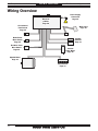
Wiring Overview ................................................88
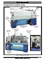
Component Location Index................................89
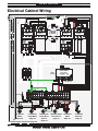
Electrical Cabinet Wiring ..................................90
Electrical Box .....................................................91
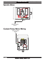
Spindle Motor .....................................................92
Coolant Pump Motor Wiring .............................92
Control Panel Wiring .........................................93
Spindle Switches ................................................93
Additional Component Wiring ..........................94
Power Connection ..............................................94
PARTS ..................................................................95
Headstock Cover ................................................95
Headstock Controls ............................................96
Headstock Internal Gears .................................98
Headstock Transfer Gears ...............................100
Gearbox Gears ..................................................101
Gearbox Controls .............................................103
Apron Front View ............................................105
Apron Rear View ..............................................107
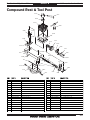
Compound Rest & Tool Post ............................109
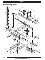
Saddle Top View ..............................................110
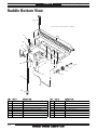
Saddle Bottom View.........................................112
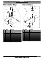
Micrometer Stop...............................................113
Dial Indicator ...................................................113
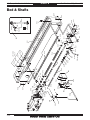
Bed & Shafts ....................................................114
End Gears .........................................................116
Main Motor .......................................................117
Stands & Panels ...............................................119
Tailstock ...........................................................121
Steady Rest ......................................................123
Follow Rest .......................................................123
Electrical Cabinet & Control Panel ................124
Accessories .......................................................125
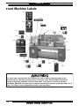
Front Machine Labels ......................................126
Rear & Side Machine Labels ...........................127
WARRANTY .......................................................129

For Machines Mfg. Since 5/11 13" Heavy 13
®
Gearhead Lathe
-3-
INTRODUCTION
About This Machine
Foreword
"The screw cutting engine lathe is the oldest and
most important of machine tools and from it all
other machine tools have been developed. It was
the lathe that made possible the building of the
steamboat, the locomotive, the electric motor, the
automobile and all kinds of machinery used in
industry. Without the lathe our great industrial
progress of the last century would have been
impossible." —How To Run a Lathe, 15th
Edition, South Bend Lathe.
The lathe represented in this manual is a
modern day version of the screw cutting lathes
that trace their roots back to the 1700's, which
were themselves technological improvements of
the bow lathe that can be traced back thousands
of years to the ancient Egyptians.
Now, almost 300 years later, these modern
"screw cutting" lathes are not just a piece of
refined machinery, but a culmination of human
ingenuity and knowledge embodied into the
design and synergy of thousands of interworking
parts—some of which represent the life's work
and dreams of many inventors, mechanical
engineers, and world-class machinists—including
the likes of Leonardo da Vinci, Henry Maudsley,
and the founders of South Bend Lathe, John and
Miles O'Brien.
And now the torch is passed to you—to take
the oldest and most important type of machine
tool—and carry on the tradition. As the operator
of a South Bend Lathe, you now join the ranks
of some very famous and important customers,
such as Henry Ford, who used the machines he
purchased to help him change the world.
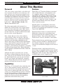
Capabilities
This Heavy 13
®
Gearhead Lathe is built for daily
use in a busy industrial setting. Loaded with
many nice features and high-precision parts, this
lathe excels at making fine tools, dies, thread
gauges, jigs, and precision test gauges—however,
it is by no means delicate. Thick castings, heavy
weight, and quality construction throughout
provide the necessary brawn for demanding
production and manufacturing tasks.
South Bend Precision Toolroom Lathe
(Circa 1958)
Features
These Heavy 13
®
Gearhead Lathes are packed
with standard features and equipment, such
as a complete coolant system, easy-to-clean
chip drawer, one-shot way lubrication system,
included steady and follow rests, chuck guard,
adjustable work lamp, foot brake, powered
cross feed, 3- and 4-jaw chucks, faceplate, and
premium Allen-Bradley contactors, thermal
relays, and fuse system.
Spindle speeds are controlled by convenient
headstock levers, which allow the operator to
quickly set the spindle speed within the available
range of 80–2000 RPM.
The beds of these lathes are constructed with
Meehanite castings that are hardened and
precision-ground in the traditional three V-way
prismatic design—long used on South Bend
Lathes for its accuracy, durability, and rigidity.
The headstocks feature quick-change gear levers
and the carriages include an adjustable clutch
that disables automatic carriage feed when it
contacts the included feed stop or in the event of
a crash.
To further ensure a high degree of accuracy,
these lathes are equipped with Japanese spindle
bearings. The spindles are D1-5 camlock with an
MT#5 taper and 1.57" bore. The tailstocks have
an MT#3 taper and 4.5" of quill travel.

-4-
For Machines Mfg. Since 5/11
13" Heavy 13
®
Gearhead Lathe
INTRODUCTION
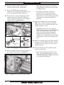
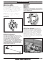
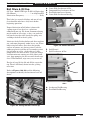
General Identification
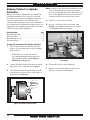
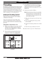
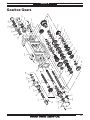
L. Longitudinal Leadscrew
M. Feed Rod
N. Coolant Reservoir & Pump Access
O. Carriage (see Page 6 for details)
P. Safety Foot Brake
Q. Chip Drawer
R. Micrometer Stop
S. Quick-Change Gearbox Controls
(see Page 5 for details)
T. Headstock Feed Direction Lever
U. Gearbox Range Lever
A. Spindle Speed Levers (see Page 50 for
details)
B. D1-5 Camlock MT#5 Spindle
C. 3-Jaw Chuck 8"
D. Chuck Guard w/Safety Switch
E. Steady Rest
F. Follow Rest
G. 4-Way Tool Post
H. Halogen Work Lamp
I. Coolant Nozzle & Valve
J. Compound Rest
K. Tailstock (see Page 7 for details)
Serious personal injury could occur if
you connect the machine to power before
completing the setup process. DO NOT
connect power until instructed to do so later
in this manual.
Untrained users have an increased risk
of seriously injuring themselves with this
machine. Do not operate this machine until
you have understood this entire manual and
received proper training.
Figure 1. Identification.
A
B
C
D
E
F
G
H
I
J
K
L
M
N
O
P
Q
R
S
T
U

For Machines Mfg. Since 5/11 13" Heavy 13
®
Gearhead Lathe
-5-
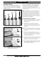
INTRODUCTION
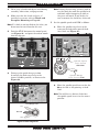
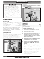
Refer to Figures 2–6 and the following
descriptions to become familiar with the basic
controls of this lathe.
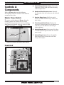
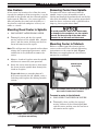
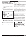
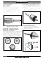
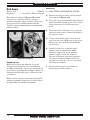
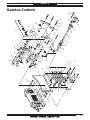
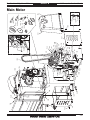
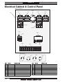
Master Power Switch
The rotary switch shown in Figure 2 toggles
incoming power ON and OFF to the lathe
controls. It also prevents the electrical cabinet
door from being opened when the switch is ON.
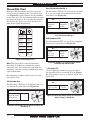
Controls &
Components
A. Quick-Change Gearbox Levers: Control the
leadscrew and feed rod speed for threading
and feed operations.
B. Headstock Feed Direction Lever: Controls
the direction that the leadscrew and feed rod
rotate.
C. Gearbox Range Lever: Shifts the quick-
change gearbox into low range, neutral, or
high range.
D. Threading and Feed Charts: Display the
necessary configuration of the gearbox levers
and end gears for different threading or
feeding options.
E. Spindle Speed Lever: Selects one of the four
available spindle speeds within the selected
speed range.
F. Spindle Range Lever: Selects the spindle
speed high range (to the left) or the low
range (to the right).
Headstock
Figure 3. Headstock controls.
F
C
E
B
A
D
Figure 2. Location of the master power switch.
Master
Power Switch

-6-
For Machines Mfg. Since 5/11
13" Heavy 13
®
Gearhead Lathe
INTRODUCTION
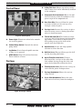
Control Panel
G. Power Light: Illuminates when lathe controls
are receiving power.
H. Coolant Pump Switch: Controls the coolant
pump motor.
I. Jog Button: Starts forward spindle rotation
as long as it is pressed.
J. STOP Button: Stops all machine functions.
Twist clockwise to reset.
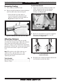
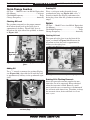
Carriage
K. 4-Way Tool Post: Mounts up to four cutting
tools at once that can be individually indexed
to the workpiece.
L. Compound Rest Handwheel: Moves the tool
toward and away from the workpiece at the
preset angle of the compound rest.
M. One-Shot Oiler: Draws oil from the apron
reservoir to lubricate the carriage ways
through various oil ports.
N. Carriage Lock: Secures the carriage in place
when to ensure accuracy during operations
where it should not move.
O . Thread Dial and Chart: Dial indicates when
to engage the half nut during inch threading
operations. Chart indicates which thread
dial reading to engage the half nut for
specific inch thread pitches.
P. Spindle Lever: Starts and stops spindle
rotation in either direction.
Q . Half Nut Lever: Engages/disengages the half
nut for threading operations.
R. Apron Feed Direction Knob: Changes
direction of the carriage or the cross slide
feed without having to stop the lathe and
move the headstock feed direction lever.
S. Feed Selection Lever: Selects the carriage or
cross slide for power feed operations.
T. Carriage Handwheel: Moves the carriage
along the bed.
U. Cross Slide Handwheel: Moves the cross
slide toward and away from the workpiece.
Figure 4. Control panel.
G
H
I
J
Figure 5. Carriage controls.
K
L
N
O
P
S
T
U
R
Q
M

For Machines Mfg. Since 5/11 13" Heavy 13
®
Gearhead Lathe
-7-
INTRODUCTION
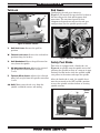
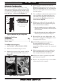
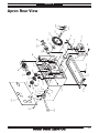
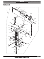
Tailstock
V. Quill Lock Lever: Secures the quill in
position.
W. Tailstock Lock Lever: Secures the tailstock in
position along the bedway.
X. Quill Handwheel: Moves the quill toward or
away from the spindle.
Y. Gib Adjustment Screw: Adjusts the tapered
gib to control tailstock offset accuracy
(1 of 2).
Z. Tailstock Offset Screw: Adjusts the tailstock
offset left or right from the spindle centerline
(1 of 2).
AA. Quill: Moves toward and away from the
spindle and holds centers and tooling.
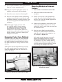
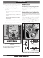
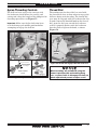
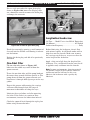
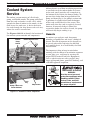
Safety Foot Brake
This lathe is equipped with a foot brake (see
Figure 8) to quickly stop the spindle instead of
allowing the spindle to coast to a stop on its own.
Pushing the foot brake while the spindle is ON
cuts power to the motor and stops the spindle.
After the foot brake is used, the spindle lever
must be returned to the OFF (middle) position
to reset the spindle switches before re-starting
spindle rotation.
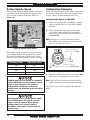
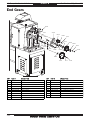
End Gears
Configuring the end gears shown in
Figure 7 will control the speed of the leadscrew
for threading or the feed rod for power feed
operations. The rotational speed of these
components depends not only on the end gear
configuration, but the spindle speed as well.
Figure 7. End gear components.
End
Gears
Figure 6. Tailstock controls.
V
W
X
Y
Z
AA
Figure 8. Foot brake and spindle lever.
Foot Brake
Spindle
Lever

-8-
For Machines Mfg. Since 5/11
13" Heavy 13
®
Gearhead Lathe
INTRODUCTION
Model Number SB1049 SB1050
Product Dimensions
Weight 1870 lbs. 2205 lbs.
Width (side-to-side)/Depth
(front-to-back)/Height
79" x 38" x 69" 90" x 38" x 69"
Foot Print (Width/Depth) 69
3
⁄4" x 19
1
⁄2" 80
3
⁄4" x 19
1
⁄2"
Shipping Dimensions
Type Wood Slat Crate
Weight 2090 lbs. 2469 lbs.
Width (side-to-side)/Depth
(front-to-back)/Height
79 x 38 x 69 79" x 45" x 69"
Electrical
Power Requirement 220V, Single-Phase, 60Hz
Full-Load Current Rating 19.5A
Minimum Circuit Size 30A
Switch Magnetic with Thermal Protection
Switch Voltage 220V
Plug Included No
Recommended Plug/Outlet Type NEMA L6-30
MODEL SB1049 & SB1050
13" HEAVY 13
®
GEARHEAD LATHES
P.O. Box 2027, Bellingham, WA 98227 U.S.A.
PHONE: (360) 734-1540 • © South Bend Lathe Co.
www.southbendlathe.com
Product Specifications
Product Specifications

For Machines Mfg. Since 5/11 13" Heavy 13
®
Gearhead Lathe
-9-
INTRODUCTION
Model Number SB1049 SB1050
Main Motor
Type TEFC Induction
Horsepower 3 HP
Voltage 220V
Phase Single-Phase
Amps 19A
Speed 1720
Cycle 60 Hz
Power Transfer V-Belt & Gear
Bearings Shielded & Permanently Sealed
Coolant Motor
Type TEFC Induction
Horsepower
1
⁄8 HP
Voltage 220V
Phase Single-Phase
Amps 0.45A
Speed 3450 RPM
Cycle 60 Hz
Power Transfer Direct Drive
Bearings Shielded & Permanently Sealed Shielded & Permanently Sealed
Operation Information
Swing Over Bed 13.38"
Distance Between Centers 30" 40"
Swing Over Cross Slide 8.26"
Swing Over Saddle 11.02"
Swing Over Gap N/A 20"
Maximum Tool Bit Size 0.75"
Compound Travel 4"
Carriage Travel 36.5"
Cross Slide Travel 7"

-10-
For Machines Mfg. Since 5/11
13" Heavy 13
®
Gearhead Lathe
INTRODUCTION
Model Number SB1049 SB1050
Headstock Information
Spindle Bore 1.57"
Spindle Taper MT#5
Number of Spindle Speeds 8
Range of Spindle Speeds 80–2000 RPM
Spindle Type D1-5 Camlock
Spindle Bearings Tapered Roller
Tailstock Information
Tailstock Quill Travel 4.5"
Tailstock Taper MT#3
Tailstock Barrel Diameter 1.968"
Threading Information
Number of Longitudinal Feeds 17
Range of Longitudinal Feeds 0.002"–0.067"
Number of Cross Feeds 17
Range of Cross Feeds 0.001"–0.034"
Number of Inch Threads 45
Range of Inch Threads 2–72 TPI
Number of Metric Threads 39
Range of Metric Threads 0.2–14 mm
Number of Modular Pitches 18
Range of Modular Pitches 0.3–3.5 MP
Number of Diametral Pitches 21
Range of Diametral Pitches 8–44 DP
Dimensions
Bed Width 9"
Leadscrew Diameter 1
1
⁄8"
Leadscrew TPI 4 TPI
Leadscrew Length 47" 59"
Steady Rest Capacity
5
⁄16"–4
5
⁄16"
Follow Rest Capacity
5
⁄8"–3
1
⁄8"
Faceplate Size 10"
Feed Rod Diameter
3
⁄4"
Floor to Center Height 42.2"
Height With Leveling Jacks 59.06"

For Machines Mfg. Since 5/11 13" Heavy 13
®
Gearhead Lathe
-11-
INTRODUCTION
Model Number SB1049 SB1050
Construction
Headstock Cast Iron
Headstock Gears Flame-Hardened Steel
Bed Meehanite Castings with Precision Hardened-and-Ground Ways
Stand Cast Iron
Paint Urethane
Other
Country of Origin Taiwan (Some Components Made in USA & Japan)
Warranty 1 Year
Serial Number Location ID Label on Front of Headstock
Assembly Time Approximately 1
1
⁄2 Hours
Sound Rating at Idle 71 dB

-12-
For Machines Mfg. Since 5/11
13" Heavy 13
®
Gearhead Lathe
SAFETY
Understanding Risks of Machinery
Operating all machinery and machining equipment can be dangerous or relatively safe depending
on how it is installed and maintained, and the operator's experience, common sense, risk awareness,
working conditions, and use of personal protective equipment (safety glasses, respirators, etc.).
The owner of this machinery or equipment is ultimately responsible for its safe use. This
responsibility includes proper installation in a safe environment, personnel training and usage
authorization, regular inspection and maintenance, manual availability and comprehension,
application of safety devices, integrity of cutting tools or accessories, and the usage of approved
personal protective equipment by all operators and bystanders.
The manufacturer of this machinery or equipment will not be held liable for injury or property
damage from negligence, improper training, machine modifications, or misuse. Failure to read,
understand, and follow the manual and safety labels may result in serious personal injury, including
amputation, broken bones, electrocution, or death.
The signals used in this manual to identify hazard levels are as follows:
Death or catastrophic
harm WILL occur.
Moderate injury or fire
MAY occur.
Death or catastrophic
harm COULD occur.
Machine or property
damage may occur.
Basic Machine Safety
Owner’s Manual: All machinery and machining
equipment presents serious injury hazards
to untrained users. To reduce the risk of
injury, anyone who uses THIS item MUST
read and understand this entire manual
before starting.
Personal Protective Equipment:
Operating or
servicing this item may expose the user
to flying debris, dust, smoke, dangerous
chemicals, or loud noises. These hazards
can result in eye injury, blindness, long-
term respiratory damage, poisoning,
cancer, reproductive harm or hearing loss.
Reduce your risks from these hazards
by wearing approved eye protection,
respirator, gloves, or hearing protection.
Trained/Supervised Operators Only: Untrained
users can seriously injure themselves
or bystanders. Only allow trained and
properly supervised personnel to operate
this item. Make sure safe operation
instructions are clearly understood. If
electrically powered, use padlocks and
master switches, and remove start switch
keys to prevent unauthorized use or
accidental starting.
Guards/Covers:
Accidental contact with
moving parts during operation may cause
severe entanglement, impact, cutting,
or crushing injuries. Reduce this risk by
keeping any included guards/covers/doors
installed, fully functional, and positioned
for maximum protection.

For Machines Mfg. Since 5/11 13" Heavy 13
®
Gearhead Lathe
-13-
SAFETY
Entanglement: Loose clothing, gloves, neckties,
jewelry or long hair may get caught in
moving parts, causing entanglement,
amputation, crushing, or strangulation.
Reduce this risk by removing/securing
these items so they cannot contact moving
parts.
Mental Alertness: Operating this item with
reduced mental alertness increases the
risk of accidental injury. Do not let a
temporary influence or distraction lead to a
permanent disability! Never operate when
under the influence of drugs/alcohol, when
tired, or otherwise distracted.
Safe Environment:
Operating electrically
powered equipment in a wet environment
may result in electrocution; operating near
highly flammable materials may result in a
fire or explosion. Only operate this item in
a dry location that is free from flammable
materials.
Electrical Connection: With electically powered
equipment, improper connections to the
power source may result in electrocution
or fire. Always adhere to all electrical
requirements and applicable codes when
connecting to the power source. Have all
work inspected by a qualified electrician to
minimize risk.
Disconnect Power: Adjusting or servicing
electrically powered equipment while it
is connected to the power source greatly
increases the risk of injury from accidental
startup. Always disconnect power
BEFORE any service or adjustments,
including changing blades or other tooling.
Secure Workpiece/Tooling:
Loose workpieces,
cutting tools, or rotating spindles can
become dangerous projectiles if not
secured or if they hit another object during
operation. Reduce the risk of this hazard
by verifying that all fastening devices are
properly secured and items attached to
spindles have enough clearance to safely
rotate.
Chuck Keys or Adjusting Tools:
Tools used to
adjust spindles, chucks, or any moving/
rotating parts will become dangerous
projectiles if left in place when the machine
is started. Reduce this risk by developing
the habit of always removing these tools
immediately after using them.
Work Area:
Clutter and dark shadows increase
the risks of accidental injury. Only operate
this item in a clean, non-glaring, and well-
lighted work area.
Properly Functioning Equipment:
Poorly
maintained, damaged, or malfunctioning
equipment has higher risks of causing
serious personal injury compared to
those that are properly maintained.
To reduce this risk, always maintain
this item to the highest standards and
promptly repair/service a damaged or
malfunctioning component. Always follow
the maintenance instructions included in
this documentation.
Unattended Operation:
Electrically powered
equipment that is left unattended while
running cannot be controlled and is
dangerous to bystanders. Always turn the
power OFF before walking away.
Health Hazards: Certain cutting fluids and
lubricants, or dust/smoke created when
cutting, may contain chemicals known to
the State of California to cause cancer,
respiratory problems, birth defects,
or other reproductive harm. Minimize
exposure to these chemicals by wearing
approved personal protective equipment
and operating in a well ventilated area.
Difficult Operations:
Attempting difficult
operations with which you are unfamiliar
increases the risk of injury. If you
experience difficulties performing the
intended operation, STOP! Seek an
alternative method to accomplish the
same task, ask a qualified expert how the
operation should be performed, or contact
our Technical Support for assistance.

-14-
For Machines Mfg. Since 5/11
13" Heavy 13
®
Gearhead Lathe
SAFETY
Additional Metal Lathe Safety
Clearing Chips. Metal chips can easily cut bare
skin—even through a piece of cloth. Avoid
clearing chips by hand or with a rag. Use a
brush or vacuum to clear metal chips.
Stopping Spindle by Hand. Stopping the spindle
by putting your hand on the workpiece
or chuck creates an extreme risk of
entanglement, impact, crushing, friction, or
cutting hazards. Never attempt to slow or
stop the lathe spindle with your hand. Allow
the spindle to come to a stop on its own or
use the brake.
Crashes. Aggressively driving the cutting tool
or other lathe components into the chuck
may cause an explosion of metal fragments,
which can result in severe impact injuries
and major damage to the lathe. Reduce
this risk by releasing automatic feeds after
use, not leaving lathe unattended during
operation, and checking clearances before
starting the lathe. Make sure no part of the
tool, tool holder, compound rest, cross slide,
or carriage will contact the chuck during
operation.
Coolant Safety. Coolant is a very poisonous
biohazard that can cause personal injury
from skin contact alone, especially when it
gets old or has been well-used. Incorrectly
positioned coolant nozzles can splash on
the operator or the floor, resulting in skin
exposure or a slipping hazard. To decrease
your risk, change coolant regularly and
position the nozzle where it will not splash
or end up on the floor.
Tool Selection. Cutting with an incorrect or
dull tool increases the risk of accidental
injury due to the extra force required for
the operation, which increases the risk of
breaking or dislodging components that
can cause small shards of metal to become
dangerous projectiles. Always select the
right cutter for the job and make sure it is
sharp. Using a correct, sharp tool decreases
strain and provides a better finish.
Speed Rates. Operating the lathe at the wrong
speed can cause nearby parts to break or the
workpiece to come loose, which will result in
dangerous projectiles that could cause severe
impact injuries. Large or non-concentric
workpieces must be turned at slow speeds.
Always use the appropriate feed and speed
rates.
Chuck Key Safety. A chuck key left in the chuck
can become a deadly projectile when the
spindle is started. Always remove the chuck
key after using it. Develop a habit of not
taking your hand off of a chuck key unless it
is away from the machine.
Safe Clearances. Workpieces that crash into
other components on the lathe may throw
dangerous projectiles in all directions,
leading to impact injury and damaged
equipment. Before starting the spindle,
make sure the workpiece has adequate
clearance by hand-rotating it through its
entire range of motion. Also, check the tool
and tool post clearance, chuck clearance, and
saddle clearance.
Long Stock Safety. Long stock can whip violently
if not properly supported, causing serious
impact injury and damage to the lathe.
Reduce this risk by supporting any stock
that extends from the chuck/headstock more
than three times its own diameter. Always
turn long stock at slow speeds.
Securing Workpiece. An improperly secured
workpiece can fly off the lathe spindle with
deadly force, which can result in a severe
impact injury. Make sure the workpiece is
properly secured in the chuck or faceplate
before starting the lathe.
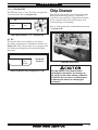
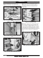
Chucks. Chucks are very heavy and difficult to
grasp, which can lead to crushed fingers or
hands if mishandled. Get assistance when
handling chucks to reduce this risk. Protect
your hands and the precision-ground ways
by using a chuck cradle or piece of plywood
over the ways of the lathe when servicing
chucks. Use lifting devices when necessary.
Page is loading ...
Page is loading ...
Page is loading ...
Page is loading ...
Page is loading ...
Page is loading ...
Page is loading ...
Page is loading ...
Page is loading ...
Page is loading ...
Page is loading ...
Page is loading ...
Page is loading ...
Page is loading ...
Page is loading ...
Page is loading ...
Page is loading ...
Page is loading ...
Page is loading ...
Page is loading ...
Page is loading ...
Page is loading ...
Page is loading ...
Page is loading ...
Page is loading ...
Page is loading ...
Page is loading ...
Page is loading ...
Page is loading ...
Page is loading ...
Page is loading ...
Page is loading ...
Page is loading ...
Page is loading ...
Page is loading ...
Page is loading ...
Page is loading ...
Page is loading ...
Page is loading ...
Page is loading ...
Page is loading ...
Page is loading ...
Page is loading ...
Page is loading ...
Page is loading ...
Page is loading ...
Page is loading ...
Page is loading ...
Page is loading ...
Page is loading ...
Page is loading ...
Page is loading ...
Page is loading ...
Page is loading ...
Page is loading ...
Page is loading ...
Page is loading ...
Page is loading ...
Page is loading ...
Page is loading ...
Page is loading ...
Page is loading ...
Page is loading ...
Page is loading ...
Page is loading ...
Page is loading ...
Page is loading ...
Page is loading ...
Page is loading ...
Page is loading ...
Page is loading ...
Page is loading ...
Page is loading ...
Page is loading ...
Page is loading ...
Page is loading ...
Page is loading ...
Page is loading ...
Page is loading ...
Page is loading ...
Page is loading ...
Page is loading ...
Page is loading ...
Page is loading ...
Page is loading ...
Page is loading ...
Page is loading ...
Page is loading ...
Page is loading ...
Page is loading ...
Page is loading ...
Page is loading ...
Page is loading ...
Page is loading ...
Page is loading ...
Page is loading ...
Page is loading ...
Page is loading ...
Page is loading ...
Page is loading ...
Page is loading ...
Page is loading ...
Page is loading ...
Page is loading ...
Page is loading ...
Page is loading ...
Page is loading ...
Page is loading ...
Page is loading ...
Page is loading ...
Page is loading ...
Page is loading ...
Page is loading ...
Page is loading ...
Page is loading ...
Page is loading ...
-
 1
1
-
 2
2
-
 3
3
-
 4
4
-
 5
5
-
 6
6
-
 7
7
-
 8
8
-
 9
9
-
 10
10
-
 11
11
-
 12
12
-
 13
13
-
 14
14
-
 15
15
-
 16
16
-
 17
17
-
 18
18
-
 19
19
-
 20
20
-
 21
21
-
 22
22
-
 23
23
-
 24
24
-
 25
25
-
 26
26
-
 27
27
-
 28
28
-
 29
29
-
 30
30
-
 31
31
-
 32
32
-
 33
33
-
 34
34
-
 35
35
-
 36
36
-
 37
37
-
 38
38
-
 39
39
-
 40
40
-
 41
41
-
 42
42
-
 43
43
-
 44
44
-
 45
45
-
 46
46
-
 47
47
-
 48
48
-
 49
49
-
 50
50
-
 51
51
-
 52
52
-
 53
53
-
 54
54
-
 55
55
-
 56
56
-
 57
57
-
 58
58
-
 59
59
-
 60
60
-
 61
61
-
 62
62
-
 63
63
-
 64
64
-
 65
65
-
 66
66
-
 67
67
-
 68
68
-
 69
69
-
 70
70
-
 71
71
-
 72
72
-
 73
73
-
 74
74
-
 75
75
-
 76
76
-
 77
77
-
 78
78
-
 79
79
-
 80
80
-
 81
81
-
 82
82
-
 83
83
-
 84
84
-
 85
85
-
 86
86
-
 87
87
-
 88
88
-
 89
89
-
 90
90
-
 91
91
-
 92
92
-
 93
93
-
 94
94
-
 95
95
-
 96
96
-
 97
97
-
 98
98
-
 99
99
-
 100
100
-
 101
101
-
 102
102
-
 103
103
-
 104
104
-
 105
105
-
 106
106
-
 107
107
-
 108
108
-
 109
109
-
 110
110
-
 111
111
-
 112
112
-
 113
113
-
 114
114
-
 115
115
-
 116
116
-
 117
117
-
 118
118
-
 119
119
-
 120
120
-
 121
121
-
 122
122
-
 123
123
-
 124
124
-
 125
125
-
 126
126
-
 127
127
-
 128
128
-
 129
129
-
 130
130
-
 131
131
-
 132
132
-
 133
133
-
 134
134
-
 135
135
-
 136
136


Ask a question and I''ll find the answer in the document
Finding information in a document is now easier with AI
Related papers
-
 South bend SB1049F Owner's manual
-
Grizzly Lathe G0740 User manual
-
Grizzly G9249 Owner's manual
-
-
-
Grizzly Industrial G0765 Owner's manual
-
-
-
-

Other documents
-
Southbend SB1049F User manual
-
Craftex CX Series CX813EXT Owner's manual
-
Harbor Freight Tools Item 93799 Owner's manual
-
Wen 3455 User guide
-
-
-
King Canada KC-1440ML-2/KM-054 User manual
-
-
-
Lindy 73013 User manual