Frigidaire FFPA1222T1 User guide

Type
User guide

This manual is also suitable for

Care and Cleaning.............................................17
Before You Call..................................................18
Major Appliance Limited Warranty................. ...19
Operating Instruction......................................8-16
Air Conditioner Features.....................................8
Installation Instructions.......................................6-7
Important Safety Instructions..............................2-3
Product Registration...............................................4
Normal Sounds.......................................................4
Unit Description......................................................5
Accessories Included.............................................5
Important Safety Instructions
NOTE:
NOTE:
WARNING
WARNING
WARNING
WARNING
SAFETY PRECAUTIONS
Important Safety Instructions
SAFETY PRECAUTIONS
NOTE:
Product Registration & Normal Sounds
Product Registration
Normal Sounds
Record Your Model and Serial Numbers
Record in the space provided below the mode and serial numbers. On all models, the
serial plate is located on the side of the cabinet.
Model No.
Serial No.
Register Your Product
The self-addressed PRODUCT REGISTRATION CARD should be filled in completely,
signed and returned to the Frigidaire Company.
At the top of the unit, you may
hear the sound of rushing air
being moved by the fan.
Sound of Rushing Air
Today’s high efficiency
compressors may have a
high pitched chatter during
the cooling cycle.
High pitched Chatter
“Gurgling or hissing” noise may be
heard due to refrigerant passing
through evaporator during normal
operation.
Gurgle/Hiss
Unit may vibrate and make noise
because of uneven floor.
Vibration
Unit Description & Accessories Included
+
Unit Description
Accessories Included
Remote Control
Battery
( )
( )
(FFPA1222T1FFPH1222T1
FFPA1422T1FFPH1422T1)
(FFPA0822T1FFPA1022T1)
Air Outlet Grill
Control Panel
Remote
Control
Carrying
Handle
Air
Exhaust
Air Intake
Castor
Power cord
Bottom
Drain Outlet
PARTS: PARTS NAME:
QUANTITY:
Window Kit Connector A
Exhaust hose connector B
Window Kit
Exhaust Hose
Screws
Safety Lock
Bolts
Foam seal B
Foam seal A
Continuous
Drain Outlet
Power
Cord
Air Intake
(FFPA1222T1FFPH1222T1
FFPA1422T1FFPH1422T1)
(FFPA0822T1FFPA1022T1)
Continuous
Drain Outlet
Bottom
Drain Outlet
Signal
Receiver
Installation Instructions
EXHAUSTING HOT AIR
In the Cool Mode the appliance must be placed close to a
window or opening so that the warm exhaust air can be ducted
outside.
First position unit on a flat floor and make sure there’s a minimum
of 12clearance around the unit, and is within the vicinity of a
single circuit outlet power source.
1. Extend either side of the hose(Fig.1) and screw the hose to
connector A (Fig.2).
2. Extend the other side of the hose and screw it to connector B
(Fig. 3).
3. Install the connector B into the unit (Fig.4).
4. Affix the connector A into the window slider kit and seal.
(Fig.5&6)
The hose can be extended from its original length of 15 up to
59,but it is the best to keep the length to minimum required.
Also make sure that the hose does not have any sharp bends
or sags.(Fig.7)
Vertical
window
Window Slider Kit
Minimum:26.6
(67.5cm)
x .
Ma mum:48 5 (123cm)
Horizontal
window
Window Slider Kit
Minimum:26.6
(67.5cm)
x .
Ma mum:48 5 (123cm)
Fig.1
Fig.2
Fig.3
Fig.5
Fig.6
Fig.7
FFPA0822T1FFPA1022T1
FFPA1222T1FFPH1222T1
FFPA1422T1FFPH1422T1
Extend the side of hose
Lock
Slide onto
1
2
Slide onto
Fig.4
FFPA0822T1FFPA1022T1
FFPA1222T1FFPH1222T1
FFPA1422T1FFPH1422T1
Installation Instructions
Installation Instructions(continued)
1.Cut the foam seals A(adhesive type) to the proper lengths and attach
them to the window and stool.(Fig.8)
2.Open the window sash and place the window slider kit on the window
stool (Fig.9). Attach the window slider kit to the window stool. Adjust
the length of the window slider kit according to the width of window.
Screw down the two screws on the window slider kit. See Fig.9.
Cut the adjustable window slider kit if the width of window is less than
26.6 inches(Fig.10).
3.Close the window sash securely against the window slider kit.(Fig.11)
4.Drive two 1 / 2 screws to secure the window slider kit to the window
sash.(Fig.11)
5.Secure the window slider kit to the window stool(Fig.11):
A: For wooden window: Use 3 / 4screws for securing.
B: For Vinyl-Clad windows: Use 1 / 2hex head cap screws for
securing.
6.To secure lower sash in place, attach right angle sash lock with 1 / 2
(12.7mm) screw as shown(Fig.12).
NOTE: It is difficult to lock the windows with the sash lock for Vinyl-Clad
windows, so you can use lock by window itself.
7.Cut the foam seal B to an appropriate length and seal the open gap
between the top window sash and outer window sash, as shown in
Fig.13.
Installation in a double-hung sash window
Installation in a sliding sash window
1.Cut the foam seals A(adhesive type) to the proper lengths and attach
them to the window frame. See Fig.14.
2.Open the window sash and place the window slider kit on the window
stool (Fig.15). Attach the window slider kit to the window stool. Adjust
the length of the window slider kit according to the height of window.
Screw down the two screws on the window slider kit. See Fig.15.
Cut the adjustable window slider kit if the height of window is less than
26.6 inches(Fig.10).
3.Close the window sash securely against the window slider kit.(Fig.16)
4.Drive two 1 / 2 screws to secure the window slider kit to the window
sash.(Fig.16)
5.Drive two 3 / 4 screws to secure the window slider kit to the window
stool.(Fig.16)
6.Cut the foam seal B to an appropriate length and seal the open gap
between the sliding sash and outer window sash, as shown in Fig.17.
7.To secure sliding sash in place, attach right angle sash lock with 1 / 2
(12.7mm) screw as shown(Fig.18).
Fig.8
Fig.9
Fig.10
Fig.14
Fig.15
Fig.16
Fig.17
Fig.18
Fig.11
Fig.12
Fig.13
screws
screws or
hex head cap screws
Window stool
Window slider kit
Foam seal B
Foam seal A
(adhesive type)
screws
Window slider kit
Window stool
Cut this to fit your window
Foam seal A
(adhesive type)
Window stool
Window slider kit
screws
Window stool
Window slider kit
screws
Foam seal B
screws
Display Temperature/Timer
Air Conditioner Features & Operating Instructions
Control Panel
Timer Mode
Selection
Adjust
Temperature
or Timer
Fan
Speed /
Filter
Reset
Power
ON/OFF
Cool mode
Press the "fan speed" button to choose the fan speed according to the illumination of the fan speed indicator.
You can choose the “hi”, “med”, “low”, or “auto” fan speed setting.
Press the “ ” or “ ”button to choose the temperature you want.
Press the “mode” button until the Cool mode indicator lights.
Operating Instruction
Fan mode
In this mode, you can select fan speed “hi”, “med”, “low” or auto” .
The screen displays room temperature.
Note: In this mode, the air exhaust hose does not need to be connected.
Press the “mode” button until the Fan mode indicator lights.
Dry mode
At the same time, the “low” fan indicator lights.
Note: In this mode, fan speed cannot be selected.
Press the “mode” button until the Dry mode indicator lights. The screen displays the room temperature.
Heat mode(For Heat & Cool models only)
Press the “ ” or “ ”button to choose the temperature you want.
At the same time, the “low” fan indicator lights.
Press the “mode” button until the Heat mode indicator lights.
Operating Instructions
When this mode initiates, the fan may not operate for the first 2 minutes to avoid blowing out cool air.
In this mode, fan speed cannot be selected.
Note:
Timer mode
How to delay startup
Plug in the unit, so the unit turns to standby.
Press the “timer” button, then the Timer indicator and number of hours on the screen will flash.
Tap or hold the UP arrow ( ) or the DOWN arrow ( ) to change delay start timer at 0.5 hour increments up
to 10 hours, then at 1 hour increments up to 24 hours.
After 5 seconds, the Timer indicator and the display stop flashing. The control will count down the time
remaining until startup.
The unit will start up in the mode as previously set.
To cancel the setting, press the “timer” button again. The timer indicator will switch off.
The timer facilitates the user to delay the unit startup or shutdown.
ECO mode
Press the "fan speed" button to choose the fan speed according to the illumination of the fan speed indicator.
You can choose the “hi”, “med”, “low”, or “auto” fan speed setting.
Press the “ ” or “ ” button to choose the temperature you want.
In few seconds after you set the temperature, the screen will display the room temperature.
Note: The unit will run in energy saver(ECO) mode when used for the first time. In this mode, the fan
will continue to run for 3 minute after the compressor shuts off. The fan then cycles on for 90
seconds at 10 minute intervals until the room temperature is above the set temperature, at which
time the compressor turns back on.
Press the “mode” button until the ECO mode indicator lights.
Operating Instructions
Filter reset
How to delay shutdown
You can delay shutdown when the unit is on.
Press the “timer” button, then the Timer indicator and number of hours on the screen will flash.
Tap or hold the UP arrow ( ) or the DOWN arrow ( ) to change delay stop timer at 0.5 hour increments up
to 10 hours, then at 1 hour increments up to 24 hours.
After 5 seconds, the Timer indicator and the display stop flashing, and the display shows the time remaining
until the unit shuts down.
To cancel the setting, press the “timer” button again. The timer indicator will switch off.
Operating Instructions
This feature is a reminder to clean the Air Filter (See Care and Cleaning) for more efficient operation.
The filter indicator will illuminate after 250 hours of operation. To reset after cleaning the filter, hold the
“fan speed” button for 5 seconds, then the “filter” indicator will go off.
Remote Control
Battery Installation and Important Instructions
Cool Only models
Heat and Cool models
Remote Control screen
Timer on button
Timer off button
Sleep button
Mode button
Temp/Timer setting button
Swing button
Fan Speed button
On/Off button
Operating Instructions
This device complies with Part 15 of the FCC Rules. Operation is subject to the following two conditions:
(1) This device may not cause harmful interference, and (2) this device must accept any interference
received, including interference that may cause undesired operation.
Remove the cover at the back of the remote control.
Insert the provided batteries correctly(see the instructions
inside the battery compartment).
Close up the cover.
To replace the old batteries(which have been used up)
with two new R03 “AAA” 1.5V batteries, repeat the
steps above.
If the remote control unit is replaced or discarded, the batteries must be removed and disposed of in
accordance with local legislation as they do harm to the environment.
Do not mix old and new batteries.
Do not mix alkaline, standard (carbon-zinc) or rechargeable (nickel-cadmium) batteries.
Do not dispose of batteries in fire. Batteries may explode or leak. If the remote control is not used for a
long time, remove the batteries from the remote control.
The remote control must be handled with extreme care. Do not drop it or expose it to direct sunlight
or sources of heat.
Point the remote control at the location of the signal receiver.
The remote control must be no more than 16 ft(5 meters)
away from the unit (without obstacles between the remote
control and the unit).
User
Remote Control
Portable AC
How to Use the Remote Control
TURNING THE UNIT ON
Plug in the unit, then press the “on/off” button (when turned on, the unit will operate as the last setting
before shutdown.
To switch the unit off, press “on/off” button again, then remove the plug.
Do NOT switch the unit off by removing the plug.
Always switch the unit off by pressing the “on/off” button and wait for few minutes before removing the plug.
Cool mode
Press the “modebutton until the left side of LCD
screen displays “ ”.
Press the “ fan speed” button to choose the fan speed
“Hi”, “Med”, “Low”, and “Auto”.
High
Medium Low Auto
Press the “ ” and “ ”button to choose the temperature you want.
Dry mode
Fan mode
Press the “modebutton until the left side of LCD
screen displays “ ”.
At the same time, the low” fan symbol appears on the screen.
Note: In this mode, fan speed cannot be selected.
Press the “modebutton until the left side of LCD
screen displays “ ”.
In this mode, you can select fan speed “Hi”, “Med”, “Low” or “Auto”
by pressing the Fan speed button and referring to the diagram.
Note: In this mode, the air exhaust hose does not need to be connected.
Operating Instructions
Heat mode(For Heat & Cool models only)
Press the “mode” button until the left side of LCD
screen displays “ ”.
Press the “ ” and “ ” button to choose the temperature you want.
At the same time, the “low” fan indicator lights.
Note: In this mode, fan speed cannot be selected.
ECO mode
screen displays “ ”.
Press the “fan speed” button to choose the “Hi”, “Med”, “Low” or
“Auto” fan speed setting.
Press the “ ” and “ ” button to choose the temperature you want.
Note: The unit will run in energy saver(ECO) mode when used for the
first time. In this mode, the fan will continue to run for 3 minute after
the compressor shuts off. The fan then cycles on for 90 seconds at 10
minute intervals until the room temperature is above the set
temperature, at which time the compressor turns back on.
Press the “mode” button until the left side of LCD
Sleep mode
Louver Swing Function
Press the “swing” button to enable louver swing function,
and the upper side of screen will display “ ”. The louver
on the top panel will swing up and down.
Press this button again to disable the louver swing function.
Operating Instructions
When the unit is in Cool, Heat or ECO mode, you can press the sleep” button
to make the unit run in Sleep mode. In this mode, the fan speed will be set as “low”
automatically, which cannot be changed.
In Cool or ECO mode the selected temperature will increase by 1 °F 60 minutes
after the mode is selected. The temperature will then increase by another 1 °F
after an additional 60 minutes. This new temperature will be maintained for 6
hours before it returns to the originally selected temperature. This ends the
"Sleep" mode and the unit will continue to operate as originally programmed.
In Heat mode, the
air conditioner will automatically decrease 1 °F per hour in
a 3 hour period. The set temperature will be steady for the next 5 hours, then this
mode will be terminated
.
The "Sleep" mode program can be cancelled at any time during operation by
pressing the "Sleep", “mode” or “fan speed” button.
Note: In Fan or Dry mode, Sleep mode cannot be set.
function
Press the “ ” button to switch between degree Fahrenheit and
degrees Celsius.
Timer mode
How to delay startup
How to delay shutdown
Press the “timer off” button, the screen displays “ ”and “H”.
Tap or hold the UP arrow ( ) or the DOWN arrow ( ) to change
delay stop timer at 0.5 hour increments up to 10 hours, then at
1 hour increments up to 24 hours. After 2 seconds, the setting
will be memorized, and the display will show the time remaining
until the unit shuts down.
To cancel the setting, press the “timer offbutton again.
You can delay shutdown when the unit is on.
Plug in the unit, so the unit turns to standby.
Press the “timer on” button, the screen will display “ ”and “H”.
Tap or hold the UP arrow ( ) or the DOWN arrow ( ) to change
delay start timer at 0.5 hour increments up to 10 hours, then at
1 hour increments up to 24 hours. After 2 seconds, the setting will be
memorized. The control will count down the time remaining until
startup. The unit will start up in the mode as previously set.
To cancel the setting, press the “timer onbutton again.
Fault Code
If the screen displays “P1”, the
should be full.
Refer to the "Drainage Instructions" on Page 16 for more instructions to drain the
successive condensate.
If error repeats, contact your Authorize Frigidaire Service Center.
on the unit water collection tank inside the unit
If the screen on the unit displays “AS”, the room temperature sensor has failed.
Contact your Authorize Frigidaire Service Center.
If the screen displays “ES”, .
Contact your Authorize Frigidaire Service Center.
on the unit the pipe temperature sensor has failed
Operating Instructions
During the DRY mode, you will need a garden hose (sold separately) to drain the condensate from the unit.
Follow the steps below:
Unscrew the drain cap of continuous drain outlet(Fig.20).
Drainage Instructions
Continuous Drainage
NOTE
Figure 20 Figure 21
Operating Instructions
Put a drip tray (not supplied) under the continuous drain outlet, then
unscrew the drain cap to allow the condensate to flow into the drip tray.
Replace the drain cap to the continuous drain outlet when no
condensate flows out.
Put the drip tray under the bottom drain outlet, then remove the
rubber stopper from the drain outlet, to allow the condensate to flow
into the drip tray. If your drip tray can’t hold all the condensate, a
number of fills will be needed.
Replace the drain cap to the bottom drain outlet when no
condensate flows out.
Note: To ensure all condensate residue has been removed, tilt the unit
by lifting it slightly upwards from the front until no more condensate
comes out from the drain outlet.
Condensate may flow out after removing the drain cap, if the unit is running in Cool or ECO mode.
When you want to remove the garden hose, prepare a drip tray (not supplied) to collect the
condensate from the drain outlet.
Please be sure that the height of the drain and section of the drain hose should not be higher than
that of the drain outlet, or the continous drainage may not work properly.
During Cool or ECO mode, it is recommended to disable continuous drainage by replacing the
drain cap to the drain outlet, to reach the maximum performance.
Figure 19
Figure 22 Figure 23
Emptying the condensate residue inside the unit during winter storage.
Connect one end of the garden hose (sold separately) to the drain outlet then lead the other end into
a drain that is lower than the unit(Fig.21).
Bottom
Drain Outlet
Drip tray
Clean your air conditioner occasionally to keep it looking new.
Be sure to unplug the unit before cleaning to prevent shock or
fire hazards.
The cabinet and front may be dusted with an oil-free cloth
or washed with a cloth dampened in a solution of warm water and
mild liquid dishwashing detergent.
Never use harsh cleaners, wax or polish on the cabinet front.
Be sure to wring excess water from the cloth before wiping around
the controls. Excess water in or around the controls may cause
damage to the air conditioner.
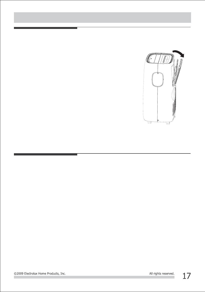
clean the filters every week of operation.
Grasp the upper panel tab and take off the filter which behind
the grill of the back panel as shown the right fig.
Wash the filter using liquid dishwashing detergent and warm water.
Rinse filter thoroughly. Gently shake excess water from the filter. Be
sure filter is thoroughly dry before replacing.
Or, instead of washing you may vacuum the filter clean.
Replace the filter after the filter is dry.
To keep your air conditioner working efficiently, you should
Care and Cleaning
Cleaning
CLEANING THE FILTERS
CLEANING THE UNIT
Winter Storage
If the air conditioner will not be used for an
extended period of time:
1.Drain the water collection tank completely
and leave the bottom drain cap and rubber plug
long time enough to allow any residual water to
drain out. Once the tank is completely drained
and no more water flows out, reinstall the rubber
plug and cap.
2.Remove and clean the filter, allow it to dry
completely, then reinstall it.
3.Remove the batteries from the remote control.
4.Store the air conditioner in a cool, dry
location, away from direct sunlight, extreme
temperature, and excessive dust.
Before using the air conditioner again:
1.Make sure the filter and drain cap are in place.
2.Check the cord to make sure it is in good
condition, without cracks or damage.
3.Place new batteries in the remote control.
4.Install the air conditioner as described in the
Installation Instructions.
Before You Call
Major Appliance Limited Warranty
  • Page 1 1
  • Page 2 2
  • Page 3 3
  • Page 4 4
  • Page 5 5
  • Page 6 6
  • Page 7 7
  • Page 8 8
  • Page 9 9
  • Page 10 10
  • Page 11 11
  • Page 12 12
  • Page 13 13
  • Page 14 14
  • Page 15 15
  • Page 16 16
  • Page 17 17
  • Page 18 18
  • Page 19 19
  • Page 20 20

Frigidaire FFPA1222T1 User guide

Type
User guide
This manual is also suitable for

Ask a question and I''ll find the answer in the document

Finding information in a document is now easier with AI