TOA VX-030DA User manual

Type
User manual

This manual is also suitable for

INSTALLATION MANUAL
DIGITAL POWER AMPLIFIER MODULES
VX-015DA
VX-030DA
VX-050DA
Thank you for purchasing TOAs Digital Power Amplier Module.
Please carefully follow the instructions in this manual to ensure long, trouble-free use of your equipment.
Indicates a potentially hazardous situation which, if mishandled, could
result in death or serious personal injury.
WARNING
1. SAFETY PRECAUTIONS
Before installation or use, be sure to carefully read all the instructions in this section for correct and safe
operation.
Be sure to follow all the precautionary instructions in this section, which contain important warnings and/or
cautions regarding safety.
After reading, keep this manual handy for future reference.
This equipment is not suitable for use in locations where children are likely to be present.
An equipment installer and the person in charge of maintenance are required to fully understand the functions
and structure of this unit, then be aware of electrical and mechanical risks before work.
Before starting work, he or she should take possible measures to prevent occurrence of such risks.
Be sure to contact your nearest TOA dealer if you need to conrm unclear points about risk sources of this
unit.
Safety Symbol and Message Conventions
Safety symbols and messages described below are used in this manual to prevent bodily injury and property
damage which could result from mishandling. Before operating your product, read this manual rst and
understand the safety symbols and messages so you are thoroughly aware of the potential safety hazards.
When Installing the Unit
Do not expose the unit to rain or an environment where it may be splashed by water or other liquids, as doing
so may result in re or electric shock.
Since the unit is designed for indoor use, do not install it outdoors. If installed outdoors, the aging of parts
causes the unit to fall off, resulting in personal injury. Also, when it gets wet with rain, there is a danger of
electric shock.
Use the unit only with the voltage specied on the unit. Using a voltage higher than that which is specied
may result in re or electric shock.
When the Unit is in Use
Should the following irregularity be found during use, immediately switch off the power, disconnect the power
supply plug from the AC outlet and contact your nearest TOA dealer. Make no further attempt to operate the
unit in this condition as this may cause re or electric shock.
· If you detect smoke or a strange smell coming from the unit.
· If water or any metallic object gets into the unit
· If the unit falls, or the unit case breaks
· If it is malfunctioning (no tone sounds.)
To prevent a re or electric shock, never open nor remove the unit case as there are high voltage components
inside the unit.
Do not place cups, bowls, or other containers of liquid or metallic objects on top of the unit. If they accidentally
spill into the unit, this may cause a re or electric shock.
Do not insert nor drop metallic objects or ammable materials in the ventilation slots of the VX-3000F’s cover,
as this may result in re or electric shock.
When replacing the fuse, be sure to use the supplied one. Using any other fuse than supplied may cause re
or electric shock.
VX-015DA: Blade 10 A
VX-030DA: Blade 20 A
VX-050DA: Blade 30 A
Be sure to switch off the amplier’s power when replacing the fuse.
Inserting or removing the fuse with the amplier’s power on may cause personal injury.
When Installing the Unit
Do not block the ventilation slots in the VX-3000F’s cover. Doing so may cause heat to build up inside the unit
and result in re. Also, periodically clean the ventilation slots of dust.
Avoid installing the unit in humid or dusty locations, in locations exposed to the direct sunlight, near the
heaters, or in locations generating sooty smoke or steam as doing otherwise may result in re or electric
shock.
Note correct polarity (positive and negative orientation) when connecting the power supply cord. Reversed
polarity connections will cause damage to the unit.
To avoid electric shocks, be sure to switch off the VX-3000F’s power when connecting the unit.
When the Unit is in Use
Do not operate the unit for an extended period of time with the sound distorting. Doing so may cause the
connected speakers to heat, resulting in a re.
Contact your TOA dealer as to the cleaning. If dust is allowed to accumulate in the unit over a long period of
time, a re or damage to the unit may result.
Indicates a potentially hazardous situation which, if mishandled, could
result in moderate or minor personal injury, and/or property damage.
CAUTION
Tip: VX-3004F, VX-3008F, and VX-3016F are collectively referred to as “VX-3000F” in this manual.
2. GENERAL DESCRIPTION
The VX-015DA, VX-030DA, and VX-050DA are Digital power amplier modules used for the VX-3000 system.
They are module types with 1 channel of class-D digital power amplier, which contributes to energy-saving
and light weight design.
The VX-015DA, VX-030DA, and VX-050DA also feature standby mode to be set for reducing standby power
consumption.
They require VX-3000F control unit and VX-3000DS (or VX-3150DS) power supply unit.
3. INSTALLATION PROCEDURE
Step 1. Shut off the power of the VX-3000F unit.
Shut off the power when the power is supplied to
the VX-3000F unit.
Step 2. Detach the front panel of the VX-3000F unit.
Remove 4 xing screws for front panel and detach
the front panel.
Step 3. Install this digital power amplier module.
Insert the digital power amplier module along the
supporting runner until it will not go any further,
then secure it using a power amplier xing screw.
Note
Use a #2 bit Philips screwdriver to tighten the xing
screw.
Step 4. Lift the lower portion of the lter of the VX-3000F
unit, then connect cables.
4-1. Connect both the power amplier module's DA
control link connector and DA output link connector
to the VX-3000F's corresponding connectors.
Use the cables supplied with the power amplier
module.
Note
After the cable connection is complete, be sure
to push the cables against the amplier side to
prevent them from protruding so that the front panel
can be easily mounted without obstructing its work.
4-2. Replace the lter.
Step 5. When installing two or more power amplier
modules, repeat Steps 3 and 4.
Step 6. Replace the front panel.
Secure it using 4 xing screws for front panel.
VX-3000F
Fixing screws for front panel
2
3
Fixing screw
VX-3000F
front
VX-015DA/
030DA/050DA
4
DA control link connector
DA output link connector
Filter
This is an electric hazard mark.
There is the possibility of an electric shock when connecting cables.
Make connections when power is not supplied to the Digital Power Amplifier Modules
VX-015DA, VX-030DA, and VX-050DA.
There is a high voltage section inside the power amplier's lter. Never
insert your nger or metallic objects inside the unit. When attaching or
detaching the connector, never touch the internal components other
than connectors.
WARNING
URL: http://www.toa.jp/
133-21-00333-03
Traceability Information for Europe
Manufacturer:
TOA Corporation
7-2-1, Minatojima-Nakamachi, Chuo-ku, Kobe, Hyogo, Japan
Authorized representative:
TOA Electronics Europe GmbH
Suederstrasse 282, 20537 Hamburg, Germany
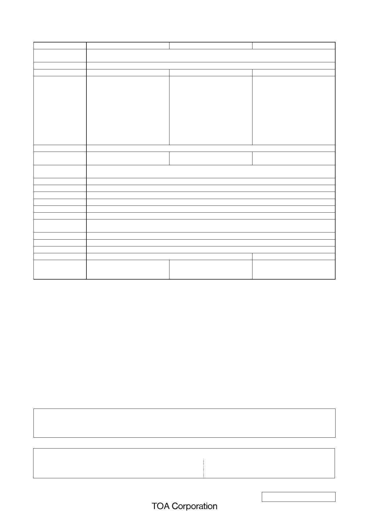
4. SPECIFICATIONS
Model Number VX-015DA VX-030DA VX-050DA
Power Source 31 V DC (operating range: 20 to 33 V DC)
DC power in: M4 screw terminal, distance between barriers: 11 mm (0.43")
Amplication System Class D
Power Consumption 40 W at 31 V DC 65 W at 31 V DC 100 W at 31 V DC
Rated Output Power 150 W (at 100 V line and min.
impedance and max. capacitive
load)
105 W (at 70 V line and min.
impedance and max. capacitive
load)
75 W (at 50 V line and min.
impedance and max. capacitive
load)
(at AC Mains VX-3000DS or
VX-3150DS*
1
: 187 to 253 V)
300 W (at 100 V line and min.
impedance and max. capacitive
load)
210 W (at 70 V line and min.
impedance and max. capacitive
load)
150 W (at 50 V line and min.
impedance and max. capacitive
load)
(at AC Mains VX-3000DS or
VX-3150DS*
1
: 187 to 253 V)
500 W (at 100 V line and min.
impedance and max. capacitive
load)
350 W (at 70 V line and min.
impedance and max. capacitive
load)
250 W (at 50 V line and min.
impedance and max. capacitive
load)
(at AC Mains VX-3000DS or
VX-3150DS*
1
: 187 to 253 V)
Output Voltage 100 V (70 V, 50 V: selectable)
Minimum Impedance
Load
67 Ω (at 100 V line), 47 Ω (at 70 V
line), 33 Ω (at 50 V line)
33 Ω (at 100 V line), 23 Ω (at 70 V
line), 17 Ω (at 50 V line)
20 Ω (at 100 V line), 14 Ω (at 70 V
line), 10 Ω (at 50 V line)
Maximum Capacitive
Load
0.5 µF
Number of Channels 1
Input DA CONTROL LINK: Nylon connector (15 pins)
Output DA OUTPUT LINK: Nylon connector (2 pins)
Frequency Response 40 Hz to 20 kHz: −5 to +1 dB (at 100 V line, 30 dB*
2
output)
Distortion 1% or less (at 100 V line, rated output, 1 kHz)
Signal to Noise Ratio 100 dB or more (at 100 V line, A-weighted)
Operating
Temperature
5 to +45 °C (23 to 113 °F)
Operating Humidity 90% RH or less (no condensation)
Finish Surface-treated steel plate
Dimensions 82.8 (w) x 91 (h) x 358.2 (d) mm (3.26" x 3.58" x 14.1")
Weight 1.3 kg (2.87 lb) 1.4 kg (3.09 lb)
Accessory DA CONTROL LINK Cable ......... 1
DA OUTPUT LINK Cable ............ 1
DC FUSE (10 A) .......................... 1
DA CONTROL LINK Cable ......... 1
DA OUTPUT LINK Cable ............ 1
DC FUSE (20 A) .......................... 1
DA CONTROL LINK Cable ......... 1
DA OUTPUT LINK Cable ............ 1
DC FUSE (30 A) .......................... 1
*
1
VX-3150DS: Power Supply Manager, equivalent of the VX-3000DS, sold only in Europe
*
2
0 dB = 1 V
Note: The design and specications are subject to change without notice for improvement.
Warning
This equipment is compliant with Class A of CISPR 32. In a residential environment this equipment may
cause radio interference.
  • Page 1 1
  • Page 2 2
  • Page 3 3
  • Page 4 4

TOA VX-030DA User manual

Type
User manual
This manual is also suitable for

Ask a question and I''ll find the answer in the document

Finding information in a document is now easier with AI