Page is loading ...

Millerfi
October
1993
Form:
OM-141
322B
Effective
With
Serial
No.
KD406035
OWNERS
MANUAL
XRTM-30R
U
Read
and
follow
these
instructions
and
all
U
Give
this
manual
to
the
operator.
U
safety
blocks
carefully.
Have
only
trained
and
qualified
persons
install,
operate,
or
service
this
unit.
Call
your
distributor
if
you
do
not
understand
the
directions.
11111
U
U
For
help,
call
your
distributor
or:
MILLER
Electric
Mfg.
Co.,
P.O.
Box
1079,
Appleton,
WI
54912
414-734-9821
'
1993
MILIER
Electric
Mtg.
Co.
Robotic
Extended
Reach
System
For
Feeding
Aluminum
Wire
For
GMAW
And
GMAW-P
Welding
For
Use
With
CV
Or
CC
Welding
Power
Source
For
.030-1/16
in
Aluminum
And
.030-045
in
Hard
Or
Cored
Wire
Control
Circuit
And
Motor
Overload
Protection
Water-Cooled
Gun
Rated
At
400
Amperes
At
100%
Duty Cycle
cover
7/93
PRINTED
IN
LISA

F
I
J
MILLERS
TRUE
BLUETM
LIMITED
WARRANTY
Effective
January
1,
1992
(Equipment
with
a
serial
number
preface
of
KC
or
newer)
This
limited
warranty
supersedes
all
previous
MILLER
warranties
and
is
exclusive
with
no
other
guarantees
or
warranties
expressed
or
implied.
LIMITED
WARRANTY
Subject
to
the
terms
and
conditions
below.
MILLER
Electric
Mfg.
Co..
Appleton,
Wisconsin,
warrants
to
its
origInal
retail
purchaser
that
new
MILLER
equipment
sold
after
the
effective
date
of
this
limited
warranty
is
free
of
de
tects
in
material
and
workmanship
at
the
time
it
is
shipped
by
MILLER.
TIllS
WAR
RANTY
IS
EXPRESSLY
IN
LIEU
OF
ALL
OTHER
WARRANTIES.
EXPRESS
OP
IMPLIED.
INCLUDING
THE
WARRANTIES
OF
MERCHANTABILITY
AND
FIT
NESS.
Within
the
warranty
perIods
listed
below,
MILLER
will
repair
or
replace
any
war
ranted
parts
or
components
that
fail
due
to
such
detects
in
material
or
workmanship.
MILLER
must
be
notified
in
writing
within
thirty
(30)
days
of
such
defector
failure,
at
which
time
MILLER
will
provide
instructions
on
the
warranty
claim
procedures
to
be
followed.
MILLER
shalt
honor
warranty
claims
on
warranted
equipment
listed
below
in
the
event
of
such
a
failure
within
the
warranty
time
periods.
All
warranty
time
periods
start
on
the
date
that
the
equipment
was
delivered
to
the
original
retail
purchaser,
or
one
year
after
the
equipment
is
sent
to
the
distributor.
I.
5
Years
Perts
3
Years
Labor
Original
main
pqwerre~tifiers
2.
3
Years
Parts
and
Labor
*
Transformer/Rectifier
Power
Sources
Plasma
Arc
Cutting
Power
Sources
Semi-Automatic
and
Automatic
Wire
Feeders
Robots
3.
2
Years
Parts
and
Labor
Engine
Driven
Welding
Generators
(NOTE:
Engines
are
warranted
separately
by
the
engine
manufacturer.)
Air
Compressors
4.
1
Year
Parts
and
Labor
*
Motor
Driven
Guns
*
Process
Controllers
*
Water
Coolant
Systems
HF
Units
Grids
Spot
Welders
Load
Banks
SDX
Transformers
Running
Gear/Trailers
Field
Options
(NOTE:
Field
options
are
covered
under
True
Blue
for
the
remaining
warranty
period
of
the
product
they
are
installed
in,
or
for
a
minimum
of
one
year
whichever
is
greater.)
6
Months
Batteries
90
Days
Parts
and
Labor
*
MIG
Guns/TIG
Torches
Plasma
Cutting
Torches
Remote
Controls
Accessory
Kits
*
Replacement
Parts
MILLERS
True
Blue
Limited
Warranty
shall
not
apply
to:
1.
Items
furnished
by
MILLER,
but
manufactured
Dy
others,
such
as
engines
or
trade
accessories.
These
items
are
covered
by
the
manufacturers
warranty,
If
any.
2.
Consumable
components;
such
as
contact
tips,
cutting
nozzles.
cOntsCtors
and
relays
or
parts
that
fail
due
to
normal
wear.
3.
Equipment
that
has
been
modified
Dy
any
party
other
than
MILLER.
or
equip
ment
that
has
been
improperly
installed,
improperly
operated
or
misused
based
upon
industry
standards.
or
equipment
which
has
not
had
reasonable
and
necessary
maintenance,
or
equipment
which
has
been
used
for
operation
outside
of
the
specifications
for
the
equipment.
MILLER
PRODUCTS
ARE
INTENDED
FOR
PURCHASE AND
USE
BY
COMMER
CIAUINDUSTRIAL
USERS
AND
PERSONS
TRAINED
AND
EXPERIENCED
IN
THE
USE
AND
MAINTENANCE
OF
WELDING
EQUIPMENT.
In
the
event
of
a
warranty
claim
covered
by
this
warranty,
the
exclusive
remedies
shall
be.
at
MILLERS
option:
(I)
repair;
or
(2)
replacement;
or.
where
authorized
in
writing
by
MILLER
in
appropriate
cases,
(3)
the
reasonable
cost
of
repair
or
replace
ment
stan
authorized
MILLER
service
station;
or
(4)
payment
of
or
credit
for
the
pur
chase
price
(less
reasonable
depreciation
based
upon
actual
use)
upon
return
of
the
900ds
at
customers
risk
and
expense.
MILLERS
option
of
repair
or
replacement
will
be
FOB,.
Factory
atAppleton,
Wisconsin,
or
FOB.
eta
MILLER
authorized
ser
vice
facility
as
determined
by
MILLER,
Therefore
no
compensation
or
reimburse
ment
for
transportation
costs
of
any
kind
will
be
allowed.
TO
THE
EXTENT
PERMITTED
BY
LAW.
THE
REMEDIES
PROVIDED
HEREIN
ARE
THE
SOLE
AND
EXCLUSIVE
REMEDIES.
IN
NO
EVENT
SHALL
MILLER
BE
LIABLE
FOR
DIRECT,
INDIRECT.
SPECIAL.
INCIDENTAL
OR
CONSEQUENTIAL
DAMAGES
(INCLUDING
LOSS
OF
PROFIT),
WHETHER
BASED
ON
CON
TRACT,
TORT
OR
ANY
OTHER
LEGAL
THEORY.
ANY
EXPRESS
WARRANTY
NOT
PROVIDED
HEREIN
AND
ANY
IMPLIED
WAR
RANTY,
GUARANTY
OR
REPRESENTATION
AS
TO
PERFORMANCE.
AND
ANY
REMEDY
FOR
BREACH
OF
CONTRACT
TORT
OR
ANY
OTHER
LEGAL
THEORY
WHICH.
BUT
FOR
THIS
PROVISION.
MIGHT
ARISE
BY
IMPLICATION,
OPERATION
OF
LAW.
CUSTOM
OF
TRADE
OR
COURSE
OF
DEALING,
IN.
CLUDING
ANY
IMPLIED
WARRANTY
OF
MERCHANTABILITY
OR
FITNESS
FOR
PARTICULAR
PURPOSE.
WITH
RESPECT
TO
ANY
AND
ALL
EQUIPMENT
FURNISHED
BY
MILLER
IS
EXCLUDED
AND
DISCLAIMED
BY
MILLER.
Some
states
in
the
U.S.A.
do
not
allow
limitations
of
how
long
an
implied
warranty
lasts,
or
the
exclusion
of
incidental,
indirect,
special
or
consequential
damages,
so
the
above
limitation
or
exclusion
may
not
apply
to
you.
This
warranty
provides
spe
cific
legal
rights.
and
other
rights
may
be
available,
but
may
vary
from
state
to
state.
In
Canada.
legislation
in
some
provinces
provides
for
certain
additional
warranties
or
remedies
other
than
as
stated
herein,
and
to
the
extent
that
they
may
not
be
waived,
the
limitations
and
exclusions
set
Out
above
may
not
apply.
This
Limited
Warranty
provides
specific
legal
rights,
and
other
rights
may
be
available,
but
may
vary
horn
province
to
province.
5.
8.
L
RECEIVING-HANDLING
Before
unpacking
equipment,
check
carton
for
any
damage
that
may
have
occurred
during
shipment.
File
any
claims
for
loss
or
damage
with
the
delivering
carrier.
Assistance
for
filing
or
settling
claims
may
be
obtained
from
distributor
and/or
equipment
manufacturers
Transportation
Department.
When
requesting
information
about
this
equipment,
always
provide
Model
Designation
and
Serial
or
Style
Number.
Use
the
following
spaces
to
record
Model
Designation
and
Serial
or
Style
Number
of
your
unit.
The
information
is
located
on
the
rating
label
or
nameplate.
Model
_________
Serial
or
Style
No.
Date
of
Purchase
miller
5/93a

ARC
WELDING
SAFETY
PRECAUTIONS
ELECTRIC
SHOCK
can
kill.
Touching
live
electrical
parts
can
cause
fatal
shocks
or
severe
burns.
The
electrode
and
work
circuit
is
electrically
live
whenever
the
output
is
on.
The
input
power
circuit
and
machine
internal
circuits
are
also
live
when
power
is
on.
In
semiautomatic
or
automatic
wire
welding,
the
wire,
wire
reel,
drive
roll
housing,
and
all
metal
parts
touching
the
welding
wire
are
electrically
live.
Incorrectly
installed
or
improperly
grounded
equipment
is
a
hazard.
1.
Do
not
touch
live
electrical
parts.
2.
Wear
dry,
hole-free
insulating
gloves
and
body
protection.
3.
Insulate
yourself
from
work
and
ground
using
dry
insulating
mats
or
covers.
4.
Disconnect
input
power
or
stop
engine
before
installing
or
servicing
this
equipment.
...-
5.
Properly
install
and
ground
this
equipment
according
to
its
Owners
Manual
and
national,
state,
and
local
codes.
6.
When
making
input
connections,
attach
proper
grounding
conductor
first.
7.
Turn
off
all
equipment
when
not
in
use.
8.
Do
not
use
worn,
damaged,
undersized,
or
poorly
spliced
cables.
9.
Do
not
wrap
cables
around
your
body.
10.
Ground
the
workpiece
to
a
good
electrical
(earth)
ground.
11.
Do
not
touch
electrode
if
in
contact
with
the
work
or
ground.
12.
Use
only
well-maintained
equipment.
Repair
or
replace
damaged
parts
at
once.
13.
Wear
a
safety
harness
if
working
above
floor
level.
14.
Keep
all
panels
and
covers
securely
in
place.
a
WARNING
ARC
WELDING
can
be
hazardous.
PROTECT
YOURSELF
AND
OTHERS
FROM
POSSIBLE
SERIOUS
INJURY
OR
DEATH.
KEEP
CHILDREN
AWAY.
PACEMAKER
WEARERS
KEEP
AWAY
UNTIL
CONSULTING
YOUR
DOCTOR.
In
welding,
as
in
most
lobs,
exposure
to
certain
hazards
occurs.
Welding
is
safe
when
precautions
are
taken.
The
safety
information
given
below
is
only
a
summary
of
the
more
complete
safety
information
that
will
be
found
in
the
Safety
Standards
listed
on
the
next
page.
Read
and
follow
all
Safety
Standards.
HAVE
ALL
INSTALLATION,
OPERATION,
MAINTENANCE,
AND
REPAIR
WORK
PERFORMED
ONLY
BY
QUALIFIED
PEOPLE.
ARC
RAYS
can
burn
eyes
and
skin;
ARC
RAYS
.~
NOISE
can
damage
hearing.
2.
Wear
a
welding
helmet
fitted
with
a
proper
shade
of
filter
(see
ANSI
Z49.
1
listed
in
Safety
Standards)
to
protect
your
face
and
Arc
rays
from
the
welding
process
produce
intense
eyes
when
welding
or
watching.
heat
and
strong
ultraviolet
rays
that
can
burn
eyes
3.
Wear
approved
safety
glasses.
Side
shields
recommended.
and
skin.
Noise
from
some
processes
can
damage
hearing.
-
4.
Use
protective
screens
or
barriers
to
protect-others
from
flash
-
and
glare;
warn
others
not
to
watch
the
arc.
NOISE
.
.
.
.
.4
5.
Wear
protective
clothing
made
from
durable,
flame.resiŒtarit
1.
Use
approved
ear
plugs
or
ear
muffs
if
noise
level
is
high.
.
material
(wool
and
leather)
and
foot
protection.
FUMES
AND
GASES
can
be
hazardous
5.
Work
in
a
confined
space
only
if
it
is
well
ventilated,
or
while
to
your
health.
wearing
an
air-supplied
respirator.
Shielding
gases
used
for
I
Welding
producesfumesandgases.
Breathing
these
welding
can
displace
air
causing
injury
or
death.
Be
sure
the
fumes
and
gases
can
be
hazardous
to
your
health.
breathing
air
is
safe.
a.
6.
Do
not
weld
in
locations
near
degreasing,
cleaning,
or
spraying
1.
Keep
your
head
out
of
the
fumes.
Do
not
breathe
the
fumes,
operations.
The
heat
and
rays
of
the
arc
can
react
with
vapors
to
form
highly
toxic
and
irritating
gases.
2.
If
inside,
ventilate
the
area
and/or
use
exhaust
at
the
arc
to
remove
welding
fumes
and
gases.
7.
Do
not
weld
on
coated
metals,
such
as
galvanized,
lead,
or
3.
If
ventilation
is
poor,
use
an
approved
air-supplied
respirator.
cadmium
plated
steel,
unless
the
coating
is
removed
from
the
4.
Read
the
Material
Safety
Data
Sheets
(MSDS5)
and
the
weld
area,
the
area
is
well
ventilated,
and
if
necessary,
while
manufacturers
instruction
for
metals,
consumables,
coatings,
wearing
an
air-supplied
respirator.
The
coatings
and
any
metals
and
cleaners.
containing
these
elements
can
give
off
toxic
fumes
if
welded.
WELDING
can
cause
fire
or
explosion.
5.
Watch
for
fire,
and
keep
a
fire
extinguisher
nearby.
Sparks
and
spatter
fly
off
from
the
welding
arc.
The
6.
Be
aware
that
welding
on
a
ceiling,
floor,
bulkhead,
or
partition
flying
sparks
and
hot
metal,
weld
spatter,
hot
workpiece,
and
hot
equipment
can
cause
fires
and
burns.
Accidental
contactof
electrode
orwelding
wire
7.
can
cause
fire
on
the
hidden
side.
Do
not
weld
on
closed
containers
such
as
tanks
or
drums.
to
metal
objects
can
cause
sparks,
overheating,
or
fire,
8.
Connect
work
cable
to
the
work
as
close
to
the
weldingarea
as
practical
to
prevent
welding
current
from
traveling
long,
possibly
1.
Protect
yourself
and
others
from
flying
sparks
and
hot
metal.
2.
Do
not
weld
where
flying
sparks
can
strike
flammable
material.
9.
unknown
paths
and
causing
electric
shock
and
fire
hazards.
Do
not
use
welder
to
thaw
frozen
pipes.
3.
Removeallflammableswithin35ft(10.7m)oftheweldingarc.
If
this
is
not
possible,
tightly
cover
them
with
approved
covers,
10.
Remove
stick
electrode
from
holder
or
cut
off
welding
wire
at
contact
tip
when
not
in
use.
4.
Be
alert
that
welding
sparks
and
hot
materials
from
welding
can
11.
Wear
oil-free
protective
garments
such
as
leather
gloves,
heavy
easily
go
through
small
cracks
and
openings
to
adjacent
areas.
shirt,
cuffless
trousers,
high
shoes,
and
a
cap.
FLYING
SPARKS
AND
HOT
METAL
can
cause
injury,
Chipping
and
grinding
cause
flying
metal.
As
welds
cool,
they
can
throw
off
slag.
1.
2.
Wear
approved
face
shield
or
safety
goggles.
Side
shields
recommended.
Wear
proper
body
protection
to
protect
skin.
.
srI
9/92
a
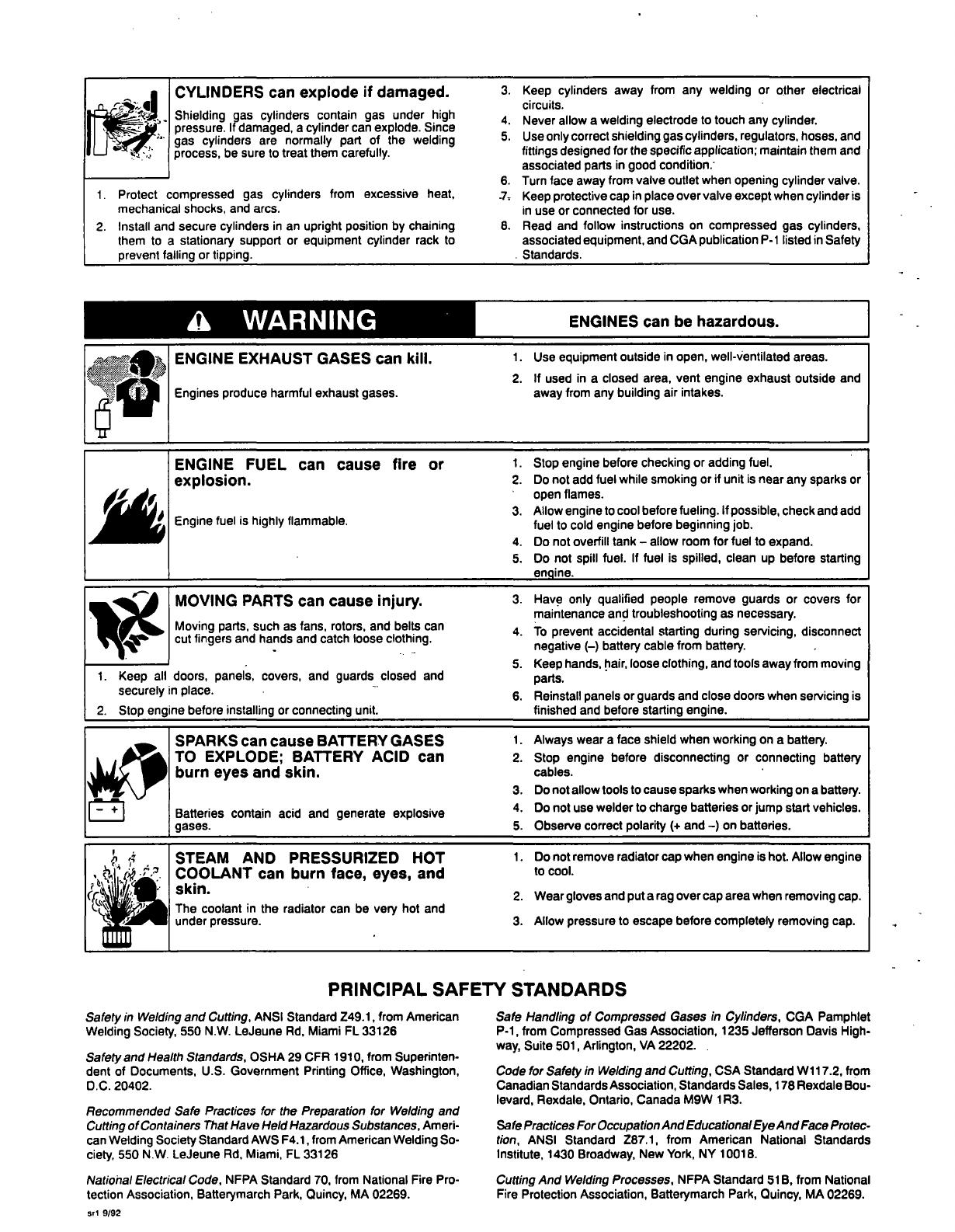
CYLINDERS
can
explode
if
damaged.
Shielding
gas
cylinders
contain
gas
under
high
pressure.
If
damaged,
a
cylinder
can
explode.
Since
gas
cylinders
are
normally
part
of
the
welding
process,
be
sure
to
treat
them
carefully.
1.
Protect
compressed
gas
cylinders
from
excessive
heat,
mechanical
shocks,
and
arcs.
2.
Install
and
secure
cylinders
in
an
upright
position
by
chaining
them
to
a
stationary
support
or
equipment
cylinder
rack
to
prevent
falling
or
tipping.
a
WARNING
3.
Keep
cylinders
away
from
any
welding
or
other
electrical
circuits.
4.
Never
allow
a
welding
electrode
to
touch
any
cylinder.
5.
Use
only
correct
shielding
gas
cylinders,
regulators,
hoses,
and
fittings
designed
for
the
specific
application;
maintain
them
and
associated
parts
in
good
condition.
6.
Turn
face
away
from
valve
outlet
when
opening
cylinder
valve.
.7~
Keep
protective
cap
in
place
over
valve
except
when
cylinder
is
in
use
or
connected
for
use.
8.
Read
and
follow
instructions
on
compressed
gas
cylinders,
associated
equipment,
and
CGA
publication
P-i
listed
in
Safety
Standards.
PRINCIPAL
SAFETY
STANDARDS
Safety
in
Welding
and
Cutting,
ANSI
Standard
Z49.1,
from
American
Welding
Society,
550
N.W.
LeJeune
Ad,
Miami
FL
33126
Safety
and
Health
Standards,
OSHA
29
CFR
1910,
from
Superinten.
dent
of
Documents,
U.S.
Government
Printing
Office,
Washington,
D.C.
20402.
Recommended
Safe
Practices
for
the
Preparation
for
Welding
and
Cutting
of
Containers
That
Have
Held
Hazardous
Substances,
Ameri
can
Welding
Society
Standard
AWS
F4.1,from
American
Welding
So
ciety,
550
N.W.
LeJeune
Ad,
Miami,
FL
33126
Natiohal
Electrical
Code,
NFPA
Standard
70,
from
National
Fire
Pro
tection
Association,
Batterymarch
Park,
Quincy,
MA
02269.
Safe
Handling
of
Compressed
Gases
in
Cylinders,
CGA
Pamphlet
P-i,
from
Compressed
Gas
Association,
1235
Jefferson
Davis
High
way,
Suite
501,
Arlington,
VA
22202.
Code
for
Safety
in
Welding
and
Cutting,
CSA
Standard
Wi
17.2,
from
Canadian
Standards
Association,
Standards
Sales,
178
Rexdale
Bou
levard,
Rexdale,
Ontario,
Canada
M9W
1
R3.
Safe
Practices
For
OccupationAnd
Educational
EyeAnd
Face
Protec
tion,
ANSI
Standard
Z87.1,
from
American
National
Standards
Institute,
1430
Broadway,
New
York,
NY
10018.
Cutting
And
Welding
Processes,
NFPA
Standard
516,
from
National
Fire
Protection
Association,
Batterymarch
Park,
Quincy,
MA
02269.
1~Tj
ILW
ENGINE
EXHAUST
GASES
can
kill.
1.
Use
equipment
outside
in
open,
well-ventilated
areas.
ENGINES
can
be
hazardous.
2.
If
used
in
a
closed
area,
vent
engine
exhaust
outside
and
Engines
produce
harmful
exhaust
gases.
away
from
any
building
air
intakes.
ENGINE
FUEL
can
cause
fire
or
1.
Stop
engine
before
checking
or
adding
fuel.
explosion.
2.
Do
not
add
fuel
while
smoking
or
if
unit
is
near
any
sparks
or
open
flames.
3.
Allow
engine
to
cool
before
fueling.
If
possible,
check
and add
Engine
fuel
is
highly
flammable.
fuel
to
cold
engine
before
beginning
job.
4.
Do
not
overfill
tank
allow
room
for
fuel
to
expand.
5.
Do
not
spill
fuel.
If
fuel
is
spilled,
clean
up
before
starting
engine.
MOVING
PARTS
can
cause
injury.
3.
Have
only
qualified
people
remove
guards
or
covers
for
maintenance
and
troubleshooting
as
necessary.
Moving
parts,
such
as
fans,
rotors,
and
belts
can
4.
To
prevent
accidental
starting
during
servicing,
disconnect
cut
fingers
and
hands
and
catch
loose
clothing,
negative
()
battery
cable
from
battery.
5.
Keep
hands,
hair,
loose
clothing,
and
tools
away
from
moving
1.
Keep
all
doors,
panels,
covers,
and
guards
closed
and
parts.
securely
in
place.
6.
Reinstall
panels
or
guards
and
close
doors
when
servicing
is
2.
Stop
eng
ne
before_installing_or
connecting_unit,
finished
and
before_starting_engine.
SPARKS
can
cause
BATTERY
GASES
1.
Always
wear
a
face
shield
when
working
on
a
battery.
TO
EXPLODE;
BATTERY
ACID
can
burn
eyes
and
skin,
2.
Stop
engine
before
disconnecting
or
connecting
battery
cables.
Batteries
contain
acid
and
generate
explosive
gases.
3.
4.
5.
Do
not
allow
tools
to
cause
sparks
when
working
on
a
battery.
Do
not
use
welder
to
charge
batteries
or
jump
start
vehicles.
Observe
correct
polarity
(+
and
)
on
batteries.
1
(.~
Y
~-.
STEAM
AND
COOLANT
can
skin.
The
coolant
in
the
r
under
pressure.
PRESSURIZED
burn
face,
eyes,
adiator
can
be
very
h
HOT
and
ot
and
1.
2.
3.
Do
not
remove
radiator
cap
when
engine
is
hot.
Allow
engine
to
cool.
Wear
gloves
and
put
a
rag
over
cap
area
when
removing
cap.
Allow
pressure
to
escape
before
completely
removing
cap.
Sri
9/92
EMF
INFORMATION
TABLE
OF
CONTENTS
SECTION
1
SAFETY
INFORMATION
1
SECTION
2
SPECIFICATIONS
2-1.
Duty
Cycle
1
SECTION
3
INSTALLATION
3-1.
Field
Installation
Instructions
For
XR-30R
Panel
Onto
Computer
Interface
3-2.
Computer
Interface
XR-30R
Interconnections
3-3.
Computer
lnter-face/XR-30R
Panel
Wire
Feeder
Connection
3-4.
Preparing
Robot
For
Installation
Of
XR-30R
3-5.
Installing
XR-30R
Gun
3-6.
Interconnecting
Harness
Connections
To
Feeder
3-7.
Installing
Wire
Spool
3-8.
Threading
Welding
Wire
3-9.
Coolant
Guidelines
SECTION
4OPERATION
14
SECTION
5-
MAINTENANCE
&
TROUBLESHOOTING
5-1.
Routine
Maintenance
17
5-2.
Changing
Or
Cleaning
Gun
Drive
Roll
18
5-3.
Changing
Feeder
And
Auxiliary
Feeder
Drive
Roll
And
Wire
Inlet
Guide
19
5-4.
Replacing
Or
Cleaning
Gun
Drive
Roll
Bearing
19
5-5.
Replacing
Or
Cleaning
Feeder
And
Auxiliary
Feeder
Drive
Roll
Bearing
20
5-6.
Replacing
Hub
Assembly
20
5-7.
Adjusting
Hub
Tension
21
5-8.
Overload
Protection
21
5-9.
Water
Flow
Switch
22
5-10.
Troubleshooting
22
0M-141
322B
10/93
NOTE
~
Considerations
About
Magnetic
Fields
The
following
is
a
quotation
from
the
General
Conclusions
Section
Welding
And
The
Effects
Of
Low
Frequency
Electric
And
To
reduce
magnetic
fields
in
the
workplace,
use
the
following
of
the
U.S.
Congress,
Office
of
Technology
Assessment,
Biological
procedures:
Effects
of
Power
Frequency
Electric
&
Magnetic
Fields
Background
Paper,
OTA-BP-E-53
(Washington,
DC:
U.S.
Government
Printing
Office,
May
1989):
.
. .
there
is
now
a
very
1.
Keep
cables
close
together
by
twisting
or
taping
them.
2.
Arrange
cables
to
one
side
and
away
from
the
operator.
large
volume
of
scientific
findings
based
on
experiments
at
the
3.
Do
not
coil
or
drape
cables
around
the
body.
cellular
level
and
from
studies
with
animals
and
people
which
clearly
establish
that
low
frequency
magnetic
fields
can
interact
with,
and
produce
changes
in,
biological
systems.
While
most
of
this
work
is
of
very
high
quality,
the
results
are
complex.
Current
scientific
understanding
does
not
yet
allow
us
to
interpret
the
evidence
in
a
4.
Keep
welding
power
source
and
cables
as
far
away
as
practical
5.
Connect
work
clamp
to
workpiece
as
close
to
the
weld
as
possible.
single
coherent
framework.
Even
more
frustrating,
it
does
not
yet
About
Pacemakers:
allow
us
to
draw
definite
conclusions
about
questions
of
possible
risk
or
to
offer
clear
science-based
advice
on
strategies
to
minimize
The
above
procedures
are
among
those
also
normally
recommended
for
pacemaker
wearers.
Consult
your
doctor
for
or
avoid
potential
risks.
complete
information.
modlO
1
4/93
2
3
4
4
5
7
10
11
13

SECTION
6
ELECTRICAL
DIAGRAMS
.
24
SECTION
7
PARTS
LIST
Figure
7-1.
Control
Box
32
Figure
7-2.
Motor
&
Wire
Drive
35
Figure
7-3.
Interface
Control,
Push/Pull
36
Figure
7-4.
Gun,
XR-30R
(MRH
Model
Illustrated)
38
Figure
7-5.
Auxiliary
Motor,
Push/Pull
(MRH)
41
Figure
7-6.
Auxiliary
Motor,
Push/Pull
(MRV6)
42
Miscellaneous
Components
44

SECTION
1
SAFETY
IN
FORMATION
Read
all
safety
messages
throughout
this
manual.
Obey
all
safety
messages
to
avoid
injury.
Learn
the
meaning
of
WARNING
and
CAUTION.
1
Safety
Alert
Symbol
modl.l
2193
3
ELECTRIC
SHOCK
can
kilI.~
Do
not
touch
live
electrical
parts.
fl
Disconnect
input
power
before
I
r
~
installing
or
servicing.
A~
CAUTION
MOVING
PARTS
can
injure.
~
~
Keeo
away
from
moving
parts.
S
Keep
all
panels
and
covers
closed
I
when
operating
I
~ti.j;~ii~~e
READ
SAFETY
BLOCKS
at
start
of
I
Section
3-1
before
proceeding.
2
Signal
Word
WARNING
means
possible
death
or
serious
injury
can
happen.
CAUTION
means
possible
minor
injury
or
equipment
damage
can
happen.
3
Statement
Of
Hazard
And
Result
4
Safety
Instructions
To
Avoid
Hazard
5
Hazard
Symbol
(If
Available)
2-1.
Duty
Cycle
a
CAUTION
USING
GUN
BEYOND
DUTY
CYCLE
RATING
can
damage
gun.
Do
not
use
gun
beyond
rated
amperage
when
using
Argon
shielding
gas.
1
2
-
~
2
/
5
6
I
NOTE
~
Turn
Oft
switch
when
using
high
frequency
6
Safety
Banner
Read
safety
blocks
for
each
sym
bol
shown.
7
NOTE
Special
instructions
for
best
oper.
~tion
not
related
to
safety.
Fig
ure
1-1.
Safety
Information
.
SECTION
2
SPECIFICATIONS
.
.
Table
2
-1.
Wire
Feeder
Specification
Description
Type
Of
Input
Power
115
Volts
AC.
3
Amperes
At
50/60
Or
100
Hz
Power
Control
Circuit
Voltage
Provided
At
Gun
30
Volts
DC
Wire
Feed
Speed
Range
70-875
ipm
(1.9-22.2
mpm)
Overall
Dimensions
Length:
19
in
(483
mm);
Width:
9-1/4
in
(235
mm):
Height:
15-1/4
in
(387
mm)
Maximum
Spool
Capacity
12
in
(305
mm)
S
Table
2-2.
Gun
Specification
Description
Input
Voltage
30
Volts
DC
Duty
Cycle
(Water-Cooled
Models)
At
400
Amperes.
100%
Using
Argon
Or
Argon
Mixture
Shielding
Gas
(See
Section
2-1)
Wire
Size
Range
.030
Thru
1/16
in
(0.8
Thru
1.6
mm)
Aluminum
Wire
.030
Thru
.045
in
(0.8
Thru
1.1
mm)
Hard
Or
Cored
Wire
Duty
cycle
is
how
long
the
gun
can
operate
within
a
ten
minute
period
without
causing
overheating
or
damage.
This
gun
is
rated
at
100%
duty
cycle
when
operated
at
400
amperes,
allowing
continuous
welding.
wfwarn8.1
if
OM-141
322
Page
1
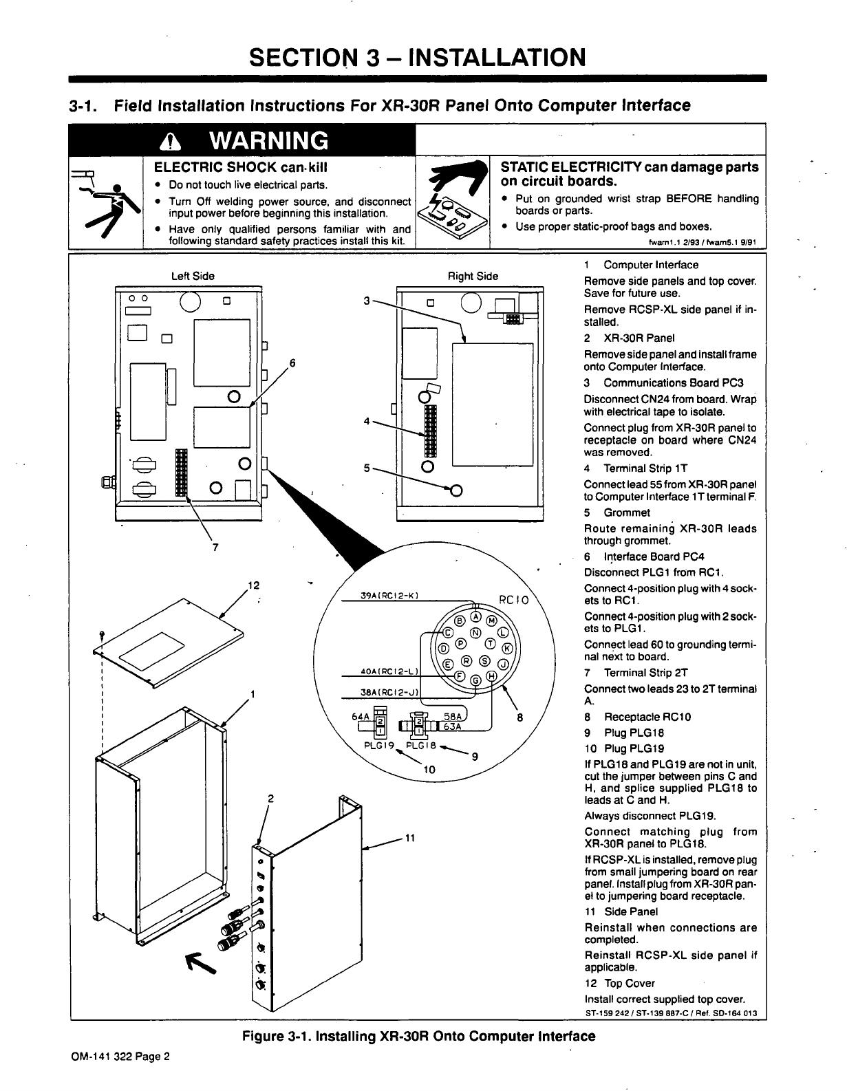
SECTION
3INSTALLATION
3-1.
Field
Installation
Instructions
For
XR-30R
Panel
Onto
Computer
Interface
a
WARNING
E
LECTRIC
SHOCK
can-kill
I
Do
not
touch
live
electrical
parts.
Turn
Off
welding
power
source,
and
disconnect
input
power
before
beginning
this
installation,
Have
only
qualified
persons
familiar
with
and
following
standard
safety
practices
install
this
kit.
STATICELECTRICITYcandamageparts
on
circuit
boards.
Put
on
grounded
wrist
strap
BEFORE
handling
boards
or
parts.
Use
proper
static-proof
bags
and
boxes.
fwaml.1
2193/fwam5.1
9/91
1
Computer
Interface
Remove
side
panels
and
top
cover.
Save
for
future
use.
Remove
RCSP-XL
side
panel
if
in
stalled.
2
XR-30R
Panel
Remove
side
panel
and
install
frame
onto
Computer
Interface.
3
Communications
Board
PC3
Disconnect
CN24
from
board.
Wrap
with
electrical
tape
to
isolate.
Connect
plug
from
XR-30R
panel
to
receptacle
on
board
where
CN24
was
removed.
4
Terminal
Strip
iT
Connect
lead
55
from
XR-30R
panel
to
Computer
Interface
1
T
terminal
F.
5
Grommet
Route
remaining
XR-30R
leads
through
grommet.
6
Interface
Board
PC4
Disconnect
PLG1
from
RC1.
Connect
4-position
plug
with
4
sock
ets
to
RC1.
Connect
4-position
plug
with
2
sock
etsto
PLG1.
Connect
lead
60
to
grounding
term
i
nal
next
to
board.
7
Terminal
Strip
2T
Connect
two
leads
23
to
2T
terminal
A.
8
Receptacle
RC1
0
9
Plug
PLG18
10
Plug
PLG19
If
PLG1
8
and
PLG1
9
are
not
in
unit,
cut
the
jumper
between
pins
C
and
H,
and
splice
supplied
PLG18
to
leads
at
C
and
H.
Always
disconnect
PLG19.
Connect
matching
plug
from
XR-30R
panel
to
PLG18.
If
RCSP-XL
is
installed,
remove
plug
from
small
jumpering
board
on
rear
panel.
Install
plug
from
XR-30R
pan
el
to
jumpering
board
receptacle.
11
Side
Panel
Reinstall
when
connections
are
completed.
Reinstall
RCSP-XL
side
panel
if
applicable.
12
Top
Cover
Install
correct
supplied
top
cover.
ST-159
242
/
ST.139
887-Cl
Ref.
SD-164
013
<1
Figure
3-1.
Installing
XR-30R
Onto
Computer
Interface
OM-141
322
Page
2
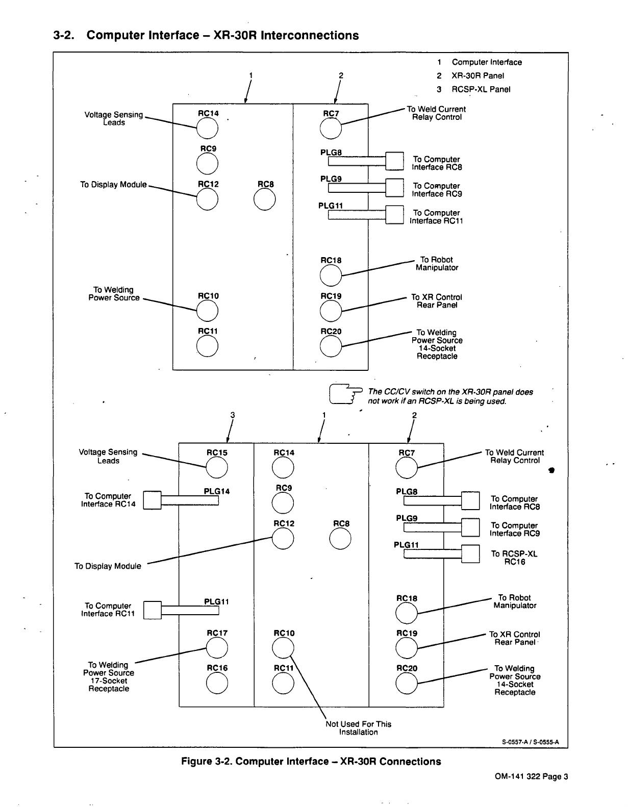
3-2.
Computer
Interface
XR-30R
Interconnections
Figure
3-2.
Computer
Interface
XR-30R
Connections
1
Computer
Interface
2
XR-30R
Panel
3
RCSP-XL
Panel
Voltage
Sensing
Leads
I
1
The
CC/CV
switch
on
the
XR.30R
panel
does
not
work
if
an
RCSP-XL
is
being
used.
RC1
5
To
Computer
Interface
RC14
/
LIIJ~
RC1
4
0
RC9
0
RC1
2
RC7
To
Weld
Current
Relay
Control
To
Display
Module
RC8
0
PLG8_-~
PLG9
PLG11
To
Computer
Interface
RC11
To
Computer
Interface
RC8
To
Computer
Interface
RC9
LII1~
To
RCSP-XL
RC1
6
To
Welding
Power
Source
17-Socket
Receptacle
RC1
8
RC1
7
RCI
6
0
To
Robot
Manipulator
RC1
0
RC1
1
O\
RC19
To
XR
Control
Rear
Panel
RC2O
To
Welding
Power
Source
14-Socket
Receptacle
\
Not
Used
For
This
Installation
S-0557-A
~
S-0555-A
OM-141
322
Page3

3-3.
Computer
lnterface/XR-30R
Panel
Wire
Feeder
Connection
Figure
3-3.
Computer
InterfacefXR-30R
Panel
Wire
Feeder
Connection
3-4.
Preparing
Robot
For
Installation
Of
XR-30R
a
WARNING
ELECTRIC
SHOCK
can
kill.
~\
S
Do
not
touch
live
electrical
parts.
Turn
Off
wire
feeder,
welding
power
source,
and
robot,
and
disconnect
input
power
before
disassembly.
The
welding
wire,
drive
rolls,
drive
assembly,
and
all
metal
parts
touching
the
welding
wire
are
electrically
live
when
welding.
1
MRH
Manipulator
2
Wire
Spool
3
Wire
Drive
Assembly
4
OutletCable
5
Welding
Gun
6
Gun
Mounting
Plate
7
MRV
Ma!pulator
8
Strain Relief
Bracket
9
Gun
Mounting
Bracket
Remove
items
from
manipulator
and
retain
for
future
use.
Retain
hardware.
1
Wire
Feeder
Receptacle
RC5
Locate
lOft
(3m)
cord
with
1
4.posi-
tion
plugs
on
both
ends.
Connect
one
end
to
RC5.
Connect
remain
ing
end
to
RC1
9
on
Computer
Inter
face/XR-30R
Panel.
Align
keyway.
insert
plug,
and
tighten
threaded
collar.
0000
Ref.
ST-159
241-A
8
7
9
5
Ref.
ST-155
650
/
Ref.
ST-i
46992
Figure
3-4.
Preparing
Robot
For
XR-30R
Installation
OM-141
322
Page
4
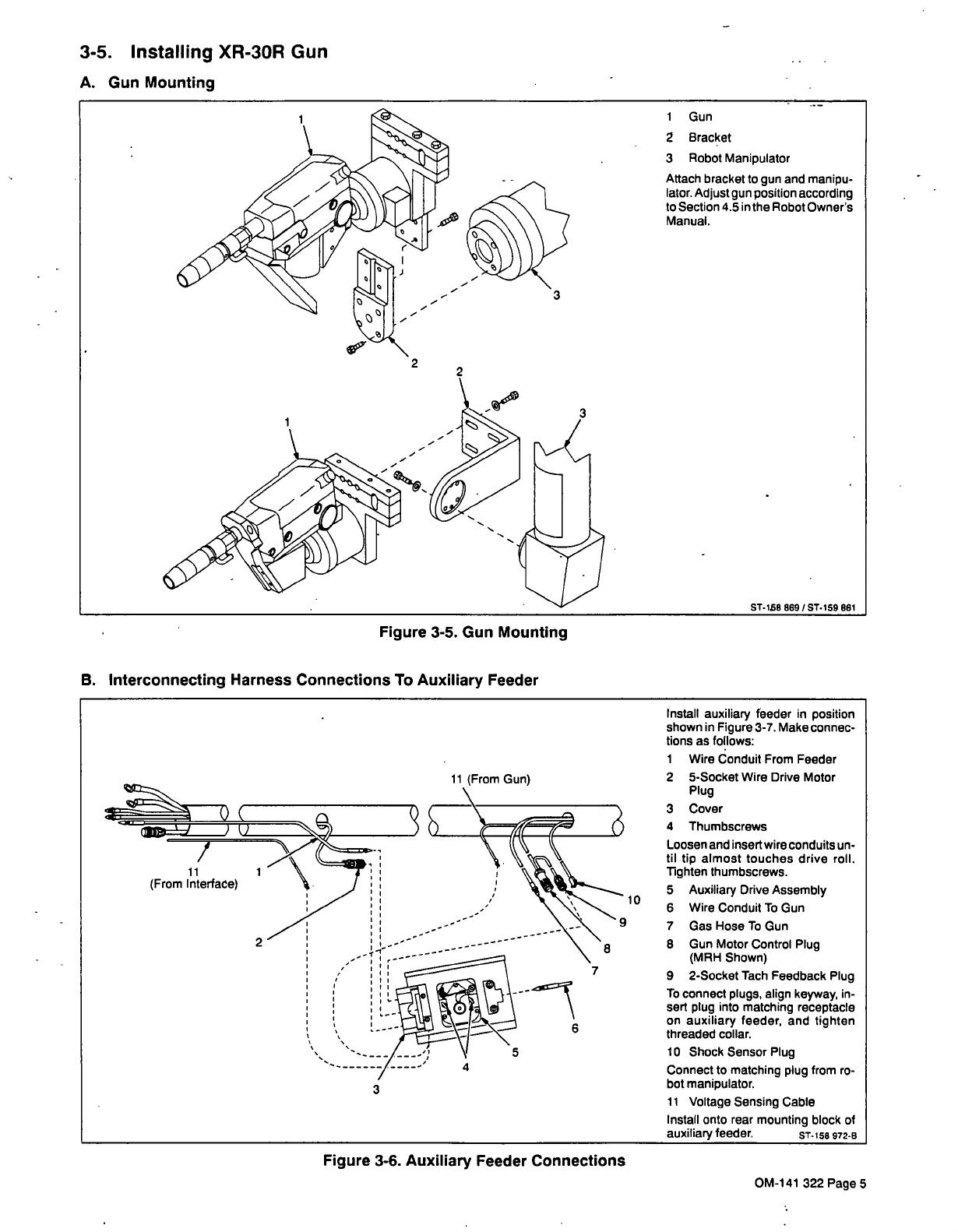
3-5.
Installing
XR-30R
Gun
A.
Gun
Mounting
Figure
3-5.
Gun
Mounting
B.
Interconnecting
Harness
Connections
To
Auxiliary
Feeder
Install
auxiliary
feeder
in
position
shown
in
Figure
3-7.
Make
connec.
tions
as
follows:
1
Wire
Conduit
From
Feeder
11
(From
Gun)
2
5-Socket
Wire
Drive
Motor
Plug
3
Cover
4
Thumbscrews
Loosen
and
insert
wire
conduits
un
til
tip
almost
touches
drive
roll.
Tighten
thumbscrews.
5
Auxiliary
Drive
Assembly
10
6
WireConduitToGun
7
Gas
Hose
To
Gun
8
8
Gun
Motor
Control
Plug
(MRH
Shown)
9
2-Socket
Tach
Feedback
Plug
To
connect
plugs,
align
keyway,
in
sert
plug
into
matching
receptacle
on
auxiliary
feeder,
and
tighten
threaded
collar.
10
Shock
Sensor
Plug
Connect
to
matching
plug
from
ro
3
bot
manipulator.
11
Voltage
Sensing
Cable
Install
onto
rear
mounting
block
of
auxiliary
feeder.
ST-158
972-B
1
Gun
2
Bracket
3
Robot
Manipulator
Attach
bracket
to
gun
and
manipu
lator.
Adjust
gun
position
according
to
Section
4.5
in
the
Robot
Owners
Manual.
ST-i5B
869
/
ST.159
861
11
(From
Interface)
2
9
5
Figure
3-6.
Auxiliary
Feeder
Connections
OM-141
322
Page
5
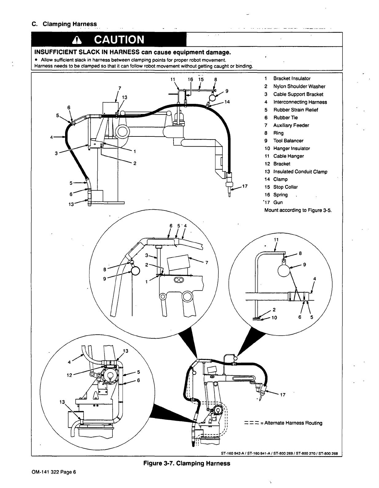
C.
Clamping
Harness
a
CAUTION
INSUFFICIENT
SLACK
IN
HARNESS
can
cause
equipment
damage.
Allow
sufficient
slack
in
harness
between
clamping
points
for
proper
robot
movement.
Harness
needs
to
be
clamped
so
that
it
can
follow
robot
movement
without
getting
caught
or
binding.
11
16
15
8
1
Bracket
Insulator
2
Nylon
Shoulder
Washer
3
Cable
Support
Bracket
4
Interconnecting
Harness
5
Rubber
Strain
Relief
6
Rubber
Tie
7
Auxiliary
Feeder
8
Ring
9
Tool
Balancer
10
Hanger
Insulator
11
Cable
Hanger
12
Bracket
13
Insulated
Conduit
Clamp
14
Clamp
17
15
Stop
Collar
16
Spring
~17
Gun
13
9
14
3
1
2
Mount
according
to
Figure
3-5.
= =
=
Alternate
Harness
Routing
ST-I
60 942-A
/
ST-i
60
941-A
I
ST-600
269
/
ST-800
270
I
5T-800
268
Figure
3-7.
Clamping
Harness
OM-141
322
Page6
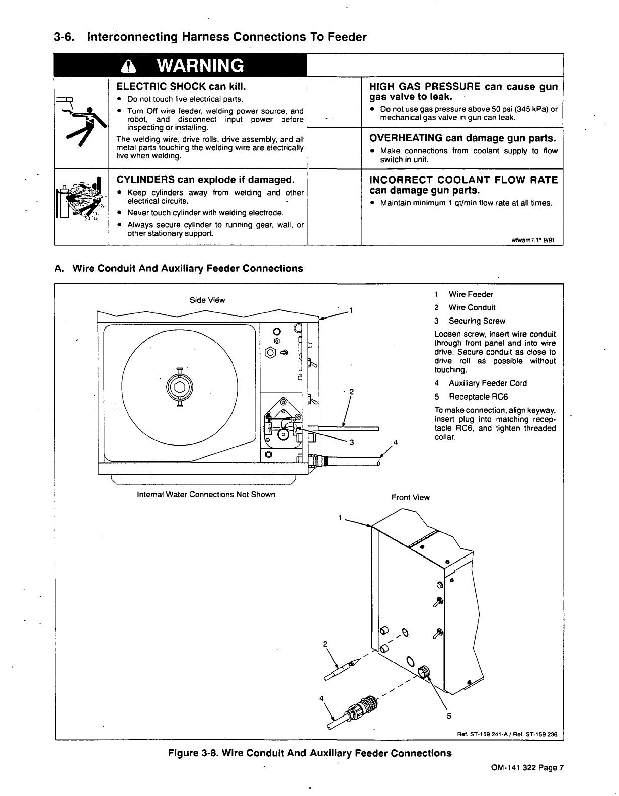
3-6.
Interonnecting
Harness
Connections
To
Feeder
_____a
WARNING
ELECTRIC
SHOCK
can
kill.
Do
not
touch
live
electrical
parts.
Turn
Off
wire
feeder,
welding
power
source,
and
robot,
and
disconnect
input
power
before
inspecting
or
installing.
The
welding
wire,
drive
rolls,
drive
assembly,
and
all
metal
parts
touching
the
welding
wire
are
electrically
live
when
welding.
A.
Wire
Conduit
And
Auxiliary
Feeder
Connections
OVERHEATING
can
damage
gun
parts.
Make
connections
from
coolant
supply
to
flow
switch
in
unit.
Figure
3-8.
Wire
Conduit
And
Auxiliary
Feeder
Connections
HIGH
GAS
PRESSURE
can
cause
gas
valve
to
leak.
gun
Do
not
use
gas
pressure
above
50
psi
(345
k
Pa)
or
-
-
mechanical
gas
valve
in
gun
can
leak.
C YLINDERS
can
explode
if
damaged.
INCORRECT
Co
OLANT
FLOW
RATE
Keep
cylinders
away
from
welding
and
other
can
damage
gun
parts.
electrical
circuits.
Maintain
minimum
1
qt/min
flow
rate
at
all
times.
Never
touch
cylinder
with
welding
electrode.
Always
secure
cylinder
to
running
gear.
wall,
or
other
stationary
support.
wlwarn7.1
9/91
Internal
Water
Connections
Not
Shown
1
Wire
Feeder
Side
View
2
Wire
Conduit
3
Securing
Screw
Loosen
screw,
insert
wire
conduit
through
front
panel
and
into
wire
drive.
Secure
conduit
as
close
to
drive
roll
as
possible
without
touching.
4
Auxiliary
Feeder Cord
5
Receptacle
RC6
To
make
connection,
align
keyway,
insert
plug
into
matching
recep.
tacle
RC6,
and
tighten
threaded
collar.
Front
View
Ret.
ST-i
59241
.A
/
Ret.
ST-i
59
236
4~
5
OM-141
322
Page7
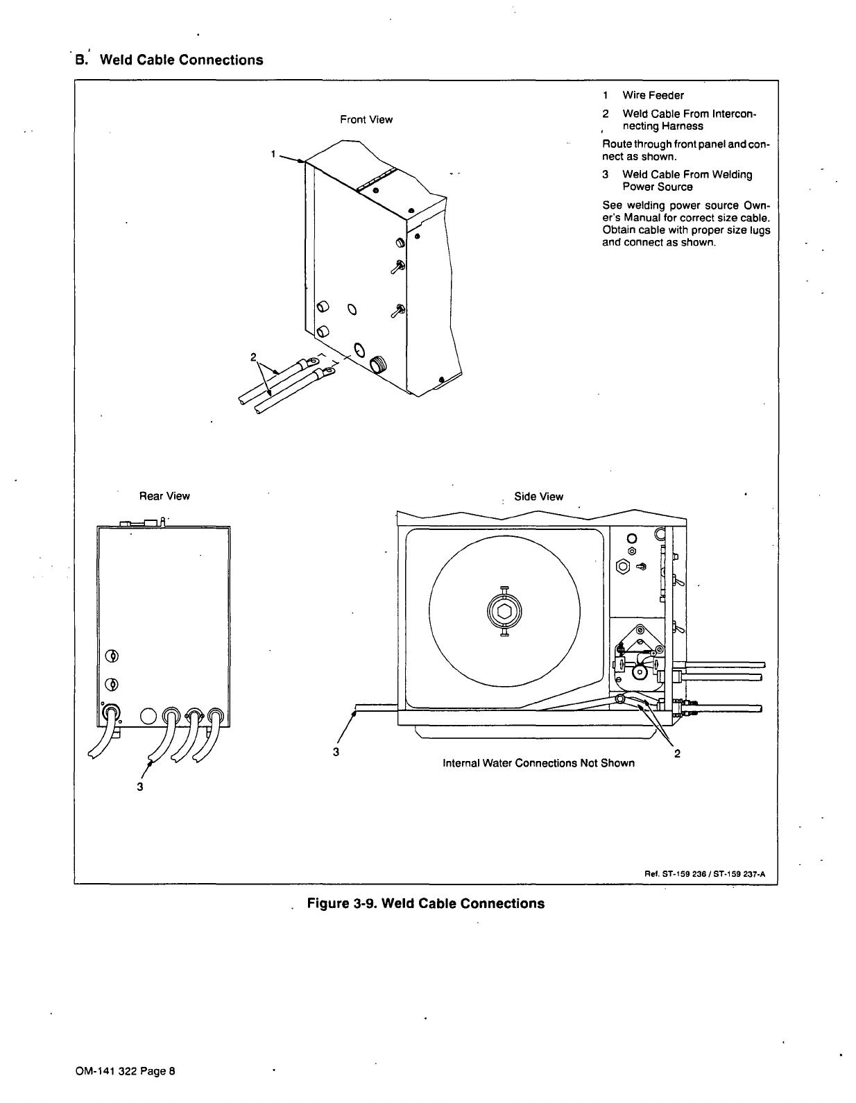
B.
Weld
Cable
Connections
Rear View
Front
View
Figure
3-9.
Weld
Cable
Connections
I
Wire
Feeder
2
Weld
Cable
From
Intercon
necting
Harness
Route
through
front
panel
and
con
nect
as
shown.
3
Weld
Cable
From
Welding
Power
Source
See
welding
power
source
Own
ers
Manual
for
correct
size
cable.
Obtain
cable
with
proper
size
lugs
and
connect
as
shown.
Ret
ST-I
59
236
/
ST-I
59
237-A
Side
View
Internal
Water
Connections
Not
Shown
OM-141
322
Page
8
C.
Water
Connections
1
Wire
Feeder
All
fittings
have
left-hand
threads.
2
Water
Hose
From
Gun
3
Water
Hose
To
Gun
Connect
water
hoses
from
inter
connecting
harness
to
fittings
on
front
panel.
4
Coolant
In
Opening
Route
hose
from
coolant
system
out
fitting,
through
opening,
and
to
fitting
on
rear
of front
panel.
Con
nect
hose.
5
Coolant
Out
Fitting
Connect
hose
from
coolant
supply
in
fitting
to
coolant
out
fitting.
6
Flow
Switch
SB
The
switch
has
a
normally-open
spring
contact
which
closes
when
0.25
gpm
(0.95
1pm)
flows
through
it.
If
the
switch
contact
does
not
close,
wire
does
not
feed.
Front
View
2
3
Rear View
Side
View
3
Internal
Water
Connections
Not
Shown
Side
View
5
Internal
Water
Connections
Shown
Figure
3-10.
Water
Connections
R&.
ST-I
59236
/
ST-I
59238-A
/
ST-I
59239-A
OM-141
322
Page
9
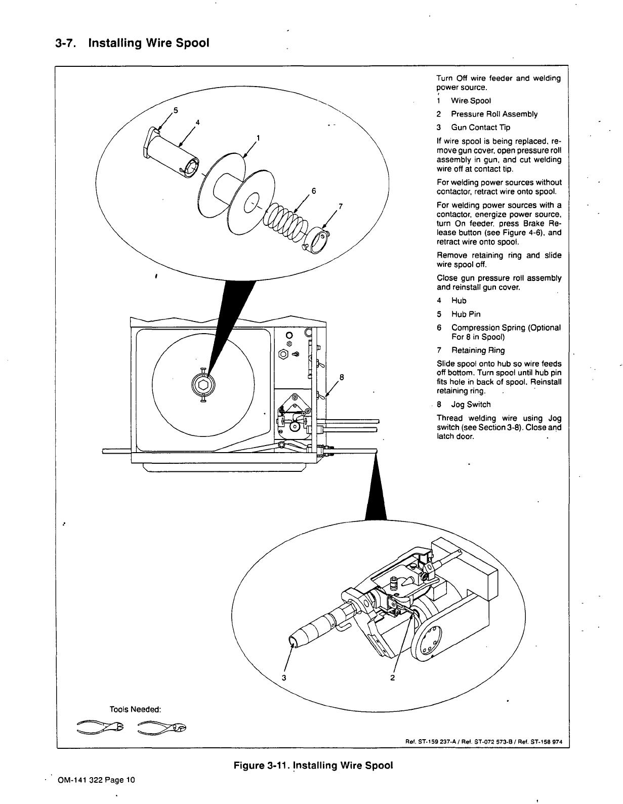
3-7.
Installing
Wire
Spool
Figure
3-11.
installing
Wire
Spool
Turn
Off
wire
feeder
and
welding
power
source.
1
Wire-Spool
2
Pressure
Roll
Assembly
3
Gun
Contact
Tip
If
wire
spool
is
being
replaced,
re
move
gun
cover,
open
pressure
roll
assembly
in
gun,
and
cut
welding
wire
off
at
contact
tip.
For
welding
power
sources
without
contactor,
retract
wire
onto
spool.
For
welding
power
sources
with
a
contactor,
energize
power
source.
turn
On
feeder,
press
Brake
Re
lease
button
(see
Figure
4-6),
and
retract
wire
onto
spool.
Remove
retaining
ring
and
slide
wire
spool
off.
Close
gun
pressure
roll
assembly
and
reinstall
gun
cover.
4
Hub
5
Hub
Pin
6
Compression
Spring
(Optional
For
8
in
Spool)
7
Retaining
Ring
Slide
spool
onto
hub
so
wire
feeds
8
off
bottom.
Turn
spool
until
hub
pin
fits
hole
in
back
of
spool.
Reinstall
retaining
ring.
-
8
Jog
Switch
Thread
welding
wire
using
Jog
switch
(see
Section
3-8).
Close
and
latch
door.
Tools
Needed:
Ref.
5T.159
237.A
/
Ref.
ST-072
573.B
/
Ref.
ST-158
974
OM-141
322
Page
10

3-8..
Threading
Welding
Wire
a
WARNING
ELECTRIC
SHOCK
can
kill.
Do
not
touch
live
electrical
parts.
The
welding
wire,
drive
rolls,
drive
assembly,
and
all
metal
parts
touching
the
welding
wire
are
electrically
live
when
welding.
HOT
SURFACES
can
burn
skin.
Allow
gun
to
cool
before
touching.
CYLINDERS
can
explode
If
damaged.
Keep
cylinders
away
from
welding
and
other
electrical
Circuits.
Never
touch
cylinder
with
welding
electrode.
Always
secure
cylinder
to
running
gear,
wall,
or
other
stationary
support.
WELDING
WIRE
can
cause
puncture
wounds.
Do
not
press
gun
trigger
until
instructed
to
do
so.
Do
not
point
gun
toward
any
part
of
the
body,
other
people,
or
any
metal
when
threading
welding
wire.
wfwam7i
9/91
A.
Threading
Welding
Wire
Through
Feeder
And
Auxiliary
Feeder
Figure
3-12.
Threading
Welding
Wire
Through
Feeder
I~TL
I
0
Be
sure
proper
drive
roll
groove
is
in
position
for
wire
size
selected
(see
Table
3.1).
Change
drive
roll
to
feed
selected
wire
size
accord
ing
to
Section
5-2.
1
Wire
Spool
Loosen
wire
from
spool,
cut
off
bent
wire,
and
pull
6
in
(150mm)
of
wire
off
spool.
2
Tension
Arm
3
Mounting
Arm
To
open
pressure
roll
assembly,
open
tension
arm
and
lift
mounting
arm.
4
Wire
Inlet
Guide
5
Drive
Roll
6
Wire
Conduit
Fitting
Thread
wire
through
wire
inlet
guide,
along
drive
roll
groove,
and
into
fitting.
Close
and
secure
pressure
roll
assembly.
7
Tension
Thurnbnut
8
Motor
Torque
Switch
Place
switch
in
proper
position
for
wire
size
selected
(see
Figure
4-6).
9
Jog
Switch
For
proper
adjustment,
loosen
thurnbnut
until
drive
roll
slips
when
Jog
switch
is
pushed
up.
Grasp
spool
with
one
hand,
and
turn
thurnbnut
clockwise
until
motor
just
stalls
when
Jog
switch
is
pushed
up.
Feed
welding
wire
through
wire
conduit
to
auxiliary
feeder.
Tighten
auxiliary
feeder
tension
thumbnut
until
it
just
touches
tension
arm.
T
ols
Needed
Tighten
2-1/2
additional
turns
0
.
clockwise.
Grasp
spool
with
one
~
hand
and
push
Jog
switch
up.
Mo
tor
should
stall.
Feed
wire
to
gun.
Rel,
ST-I
59240-A
/
Ref.
ST-I
51
778
2
OM-141
322
Page
11

B.
Threading
Welding
Wire
Through
Gun
READ
SAFETY
BLOCKS
at
start
of
Section
3-8
before
proceeding.
Table
3-1.
Gun
Part
Recommendations
For
Wire
Size
Changing
Parts
Aluminum
Wire
Hard
And
Flux
Cored
Wire
.030
in
.035
in
.045
in
3/64
in
1/16
in
.030
in
.035
in
.045
in
Drive
Roll
Grove
A
(small
groove)
X
X
X
X
Drive
Roll
Grove
B
(large
groove)
X X X
X
Contact
Tip
Part
No.
108
788
0.8
R
Contact
Tip
Part
No.
108
789
0.9
R
0.9
n
Contact
Tip
Part
No.
125
988
1.0
R
Contact
Tip
Part
No.
113
954
1.2
M
1.2
M
Contact
Tip
Part
No.
113
955
1.6
M
Liner
Part
No.
141
222
.055
in
ID
.055
in
ID
.055
in
ID
.055
in
ID
.055
in
ID
.055
in
ID
.055
in
ID
Liner
Part
No.
141
223
.093
in
ID
1
Pressure
Roll
Assembly
Lift
arm
and
open
pressure
roll
assembly.
2
Jog
Switch
Push
Jog
switch
up
to
feed
wire
through
wire
conduit.
3
Drive
Roll
(See
Table
3-1)
4
Contact
Tube
(See
Table
3.1)
Manually
thread
wire
along
drive
roll
groove
and
out
contact
tip
2
in
(51
mm).
Close
pressure
roll
assembly.
5
Pressure
Adjustment
Knob
6
Final
Pressure
Adjustment
Turn
On
feeder
and
check
drive
roll
pressure
by
feeding
wire
against
a
piece
of
wood
or
concrete
surface;
wire
should
feed
steadily
without
slipping.
If
necessary,
adjust
pres
sure
adjustment
knob
in
gun.
Wire
should
not
be
nicked
or
kinked
or
burnback
problems
can
result.
Turn
Off
feeder
and
welding
power
source.
Reinstall
gun
cover.
Close
and
latch
feeder
door.
Ref.
ST.158
974
/
Ref.
ST-158
973
/
Ref.
S-0651
Figure
3-13.
Threading
Welding
Wire
Through
Gun
OM-141
322
Page
12
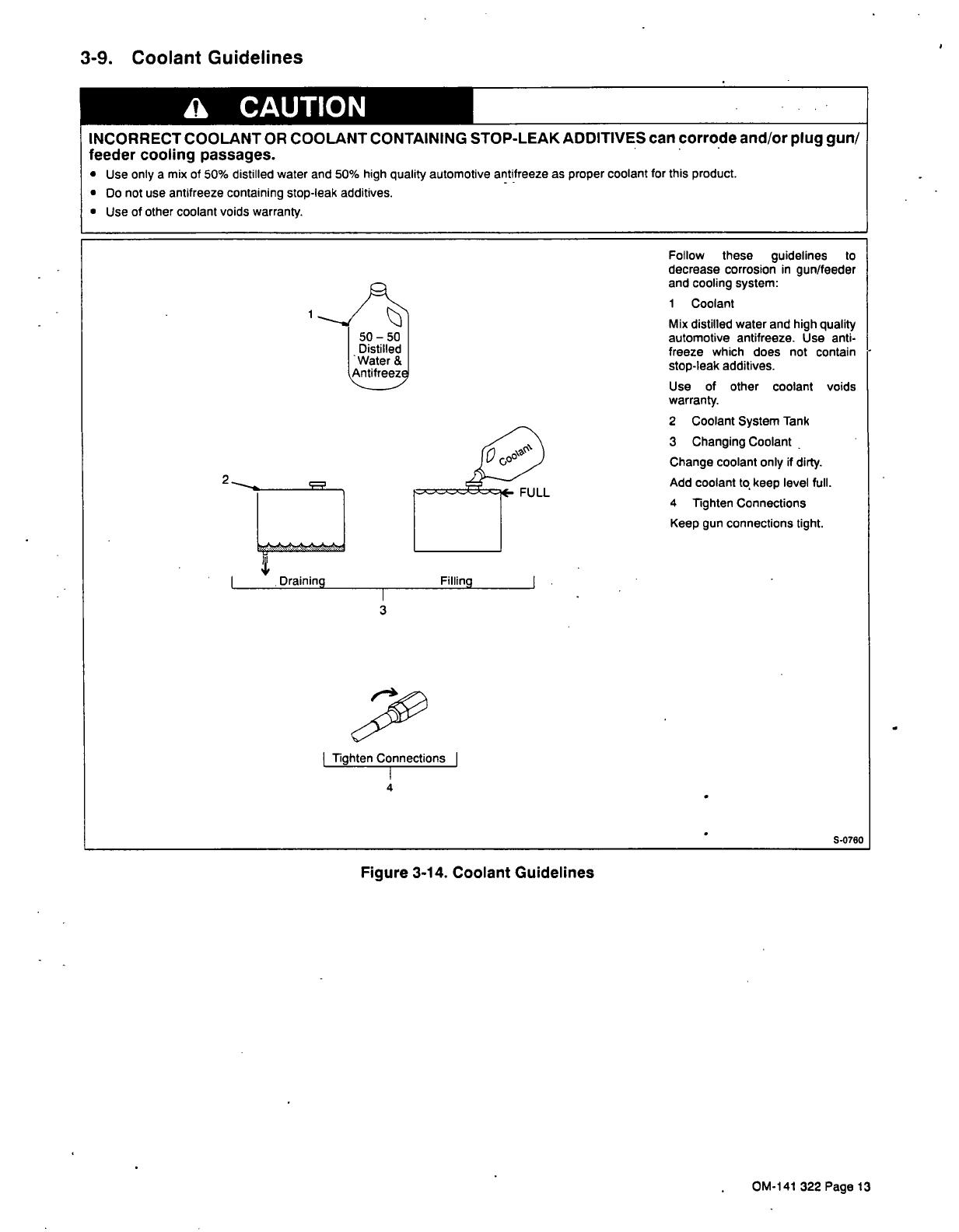
3-9.
Coolant
Guidelines
a
CAUTION
INCORRECT
COOLANT
OR
COOLANT
CONTAINING
STOP-LEAK
ADDITIVES
can
corrode
and/or
plug
gun/
feeder
cooling
passages.
Use
only
a
mix
of
50%
distilled
water
and
50%
high
quality
automotive
antifreeze
as
proper
coolant
for
this
product.
Do
not
use
antifreeze
containing
stop-leak
additives.
Use
of
other
coolant voids
warranty.
50
50
Distilled
Water
&
Antifreez
Filling
Follow
these
guidelines
to
decrease
corrosion
in
gun/feeder
and
cooling
system:
I
Coolant
Mix
distilled
water
and
high
quality
automotive
antifreeze.
Use
anti
freeze
which
does
not
contain
stop-leak
additives.
Use
of
other
coolant
warranty.
2
Coolant
System
Tank
3
Changing
Coolant
Change
coolant
only
if
dirty.
Add
coolant
to
keep
level
full.
4
Tighten
Connections
Keep
gun
connections
tight.
voids
Tighten
Connections
4
Figure
3-14.
Coolant
Guidelines
S-0780
FULL
Drainina
3
OM-141
322
Page
13
SECTION
4-OPERATION
a
WARNING
ELECTRIC
SHOCK
can
kill.
Do
not
touch
live
electrical
parts.
Always
wear
dry
insulating
gloves.
Insulate
yourself
from
work
and
ground.
Keep
all
panels
and
covers
securely
in
place
FUMES
AND
GASES
can
be
hazardous
to
your
health.
Keep
your
head
out
of
the
fumes.
Ventilate
area,
or
use
breathing
device.
Read
Material
Safety
Data
Sheets
(MSDSs)
and
manufacturers
instructions
for
material
used.
WELDING
can
cause
fire
or
explosion.
Do
not
weld
near
flammable
material.
Watch
for
fire;
keep
extinguisher
nearby.
Do
not
locate
unit
over
combustible
surfaces.
Do
not
weld
on
closed
containers.
Allow
work
and
equipment
to
cool
before
handling.
-~
~
~-
ARC
RAYS
can
burn
eyes
and
skin;
NOISE
can
damage
hearing.
Wear
welding
helmet
with
correct
shade
of
filter.
Wear
correct
eye,
ear,
and
body
protection.
,..,~
~
~
MOVING
PARTS
can
cause
injury.
Keep
away
from
pinch
points
such
as
drive
rolls.
Keep
all
doors,
panels,
covers,
and
guards
closed
and
securely
in
place.
-
.~.....
MAGNETIC
FIELDS
FROM
HIGH
CUR
RENTS
can
affect
pacemaker
operation.
Pacemaker
wearers
keep
away.
Wearers
should
consult
their
doctor before
going
near
any
welding
operations.
See
Safety
Precautions
at
beginning
of
welding
power
source
Owners
Manual
for
basic
welding
safety
information.
.
wfwarn3.I
8/92
Figure
4-2.
Safety
Equipment
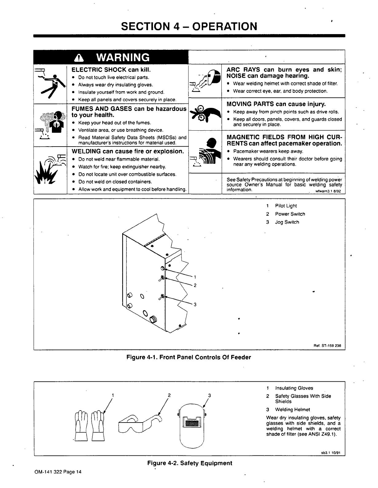
1
Pilot
Light
2
Power
Switch
3
Jog
Switch
2
3
Figure
4-1.
Front
Panel
Controls
Of
Feeder
Ret.
ST-I
59
236
I
Insulating
Gloves
2
3
2
Safety
Glasses
With
Side
/
Shields
3
Welding
Helmet
Wear
dry
insulating
gloves,
safety
_______
glasses
with
side
shields,
and
a
welding
helmet
with
a
correct
shade
of
filter
(see
ANSI
Z49.l).
sb3.I
tO/91
OM-141
322
Page
14
/