CLT-4HSW4/CLX-4HSW4
Terminal Block and Module
Installation Guide
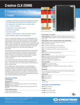
Description
The Crestron
®
4-Feed, 4-High Switch Terminal Block and Module (CLT-4HSW4 and
CLX-4HSW4, respectively), are considered a single entity and must be used together.
They ship separately to permit termination of the eld wiring to the CLT-4HSW4 prior to
installation of the CLX-4HSW4, as described in this guide. They can be mounted in CAEN
or CAEN-MLO enclosure (both not included).
The terminal block is designed to terminate four circuit feeds (LINE and NEUTRAL) and
distribute the controlled circuits (LOAD) to the xtures. The module connects to the
terminal block and performs switching control of four lighting or motor loads.
The maximum load is 16 amps (1/2 HP) for each controlled circuit (64 amps total per
module). The unit requires 120 Vac 60 Hz input voltage. An oversize heat sink dissipates
heat efciently. There are LEDs on the module to indicate communication to a Cresnet
®
network, input power to the module, and output power to the load.
The CLT-4HSW4 terminal block has a color-coded DIN rail design, complete with printed
label strips and mounting hardware, that provides for a clean and simple installation.
Electrical bypass jumpers on each terminal facilitate testing of each circuit and protect the
module during installation.
Specications for the CLT-4HSW4 and CLX-4HSW4 are listed in the table below.
SPECIFICATION DETAILS
Load Control
Switch Channels
Switched Load Types
Per Channel Load Rating
Module Total Load Rating
Line/Load Voltage
4
LED, incandescent, uorescent, magnetic
low-voltage, electronic low-voltage, neon/cold
cathode, high-intensity discharge (HID), motor
16 A, 1/2 HP
64 A
120 Vac, 60Hz; requires up to four single-phase feeds
(may be same or different phases)
Environmental
Temperature
Humidity
Heat Dissipation
32º to 104 ºF (0º to 40 ºC)
10% to 90% RH (noncondensing)
16 Btu/hr + (0.41 Btu/hr x Load Current in Amps);
42 Btu/hr at maximum load
Additional Resources
Visit the product page on the Crestron website
(www.crestron.com) for additional information
and the latest rmware updates. Use a QR reader
application on your mobile device to scan the QR
image.
CLT-4HSW4 CLX-4HSW4
Terminal Block and Module Installation
The terminal block and module must be mounted into an enclosure by a licensed electrician
and in accordance with all national and local codes.
CAUTION: This equipment is for indoor use only and needs to be air-cooled. Mount in
a well-ventilated area. The ambient temperature must be 32º to 104 ºF (0º to 40 ºC). The
relative humidity must be 0% to 90% (noncondensing).
Terminal blocks are installed along the left side of single-wide enclosures and along the
outside edges (left and right sides) of double-wide enclosures. Modules are installed along
the right side of single-wide enclosures and side-by-side in the center of double-wide
enclosures. When installing modules and terminal blocks in a double-wide enclosure,
be sure to invert units on the right side so that they can be properly wired. Refer to the
following illustrations for details
NOTE: Install the modules and terminal blocks into the lowest available spaces and
continue toward the top of the enclosure.
Terminal Block and Module Locations in a Single-wide Enclosure
Ground bus
CLT- terminal
block
CLX- module
SW 1
N IN 1
N OUT 1
LINE 2
N OUT 3
LINE 4
SW 4
N IN 4
N OUT 4
SW 2
N IN 2
N OUT 2
LINE 3
SW 3
LINE 1
N IN 3
CLX-4HSW4
4 FEED
4 HI-INRUSH
SWITCHES
120VAC 60 Hz
16A MAX/FEED
Terminal Block and Module Locations in a Double-wide Enclosure
Ground bus
CLT- terminal block
CLT- terminal block
CLX- module
SW 1
N IN 1
N OUT 1
LINE 2
N OUT 3
LINE 4
SW 4
N IN 4
N OUT 4
SW 2
N IN 2
N OUT 2
LINE 3
SW 3
LINE 1
N IN 3
CLX-4HSW4
4 FEED
4 HI-INRUSH
SWITCHES
120VAC 60 Hz
16A MAX/FEED
SW 1
N IN 1
N OUT 1
LINE 2
N OUT 3
LINE 4
SW 4
N IN 4
N OUT 4
SW 2
N IN 2
N OUT 2
LINE 3
SW 3
LINE 1
N IN 3
CLX-4HSW4
4 FEED
4 HI-INRUSH
SWITCHES
120VAC 60 Hz
16A MAX/FEED
NOTE: Unless otherwise indicated, the lighting system specied in this guide is
modular, requiring assembly in the eld by a licensed electrician, in accordance with all
national and local codes.
If you require an assembled UL Listed panel, Crestron offers this service through its UL
Listed panel shop. This includes complete in-factory system conguration and assembly
by Crestron for an additional fee.
Terminal Block Installation and Field Wiring
NOTE: Both left-side and right-side adhesive wiring labels are provided. The left-side
labels are used in both single-wide and double-wide enclosures. The right-side labels are
only used in double-wide enclosures.
1. Remove the backing from the left or right adhesive wiring label.
2. Apply the adhesive label by aligning the holes in the label with the holes on the
enclosure where the terminal block is to be mounted. The wiring label lies beneath the
terminal block as shown in the illustrations that follow.
3. Use the two supplied self-tapping pan Phillips screws (8B x 1/4”) to secure the
terminal block to the Crestron Automation Enclosure.
CAUTION: Bypass jumpers are provided to allow testing of circuits and to protect
the module during installation. When properly secured by two screws, each of the
four jumpers on the black and red sections of the terminal block shorts the line in to
the switch out so that the circuit is energized. Do not remove any bypass jumpers
until all feed and load wiring has been completed, the circuit has been tested for
electrical faults, and the module has been installed. Refer to “Module Installation”
section for details.
Furthermore, the four jumpers on the white sections of the terminal block tie the
neutral ins to the neutral outs. These jumpers should never be removed.
NOTE: Use copper conductors only – rated 75 ºC
4. With the circuit breaker turned off, connect the circuit feed (LINE and NEUTRAL) and
controlled circuit (LOAD) wires to the terminal block per the markings provided on the
wiring label (as shown in the diagrams on this page). Terminal blocks accept one
14 - 10 AWG wire. Wires should be stripped to ½ inch. Tighten terminal blocks
to 9 in-lbs.
5. Grounding terminal blocks are available in the cabinet for termination of ground wires.
Tighten the ground wires to 35 in-lbs. (14 – 10 AWG), 40 in-lbs. (8 AWG), or 45 in-lbs.
(6 – 4 AWG).
6. Test each circuit for electrical faults by turning on each of the circuit breakers,
checking that the breakers do not trip, and that power is delivered to the proper loads.
Wiring Diagram of the Terminal Block to the Feed and Load(s) (Single-wide and Left Side
Double-wide Enclosures)
Bypass
jumpers
Terminal
block
Left-side
wiring label
SW 1
N IN 1
N OUT 1
LINE 2
N OUT 3
LINE 4
SW 4
N IN 4
N OUT 4
SW 2
N IN 2
N OUT 2
LINE 3
SW 3
LINE 1
N IN 3
Module
location
label
CLX-4HSW4
4 FEED
4 HI-INRUSH
SWITCHES
120VAC 60 Hz
16A MAX/FEED
Line 1
Line 2
Line 3
Line 4
To
load 1
To
load 2
To
load 3
To
load 4
Neutral
Neutral
Neutral
Neutral
Ground bus
GND
Wiring Diagram of the Terminal Block to the Feed and Load(s) (Right Side Double-wide
Enclosures)
Bypass
jumpers
SW 1
N IN 1
N OUT 1
LINE 2
N OUT 3
LINE 4
SW 4
N IN 4
N OUT 4
SW 2
N IN 2
N OUT 2
LINE 3
SW 3
LINE 1
N IN 3
Module
location
label
Line 4
Line 3
Line 2
Line 1
To
load 4
To
load 3
To
load 2
To
load 1
Neutral
Neutral
Neutral
Neutral
Ground bus
GND
CLX-4HSW4
4 FEED
4 HI-INRUSH
SWITCHES
120VAC 60 Hz
16A MAX/FEED

Module Installation
CAUTION: The module contains electrostatic sensitive devices (ESDs); the unit must
be handled from the metal chassis – do not touch the PC board or components.
NOTE: Install the modules after the enclosure has been completely wired. Refer to the
terminal block installation procedure in the previous section for details.
1. Use the four supplied self-tapping pan Phillips screws (8B x 1/4”) to secure the
module to the enclosure.
2. As shown in the wiring diagrams, connect the wires from the module to the terminal
block. Each wire exits the module directly in line with, and is the same color as, the
terminal to which it should be connected. Wires are prestripped to 1/2 inch. Tighten
to 9 in-lbs.
3. If the module is being installed above another module within the enclosure, attach
the supplied module interconnect cable between the two modules. The illustration
below depicts the area within a double-wide enclosure where the corners of four
modules meet.
NOTE: One wire on the module interconnect cable may be a different color from
the rest. The color has no bearing on its orientation during installation.
Use Module Interconnect Cable to Wire Module to Module
Module interconnect
cable attached
Connection not
made
4. Turn on the circuit breakers and verify that the green PWR LED on the module lights,
the breakers do not trip, and power is delivered to the proper loads.
5. Turn off the circuit breakers and remove the two-position bypass jumpers on the
black and red sections of the terminal block. The jumpers on the white sections of
the terminal block remain installed.
NOTE: Before the two-position bypass jumpers are removed, the control system
should be properly connected and contain a valid program to provide control of
the module.
Wiring Diagram of the Terminal Block to the Module (Single-wide and Left-Side
Double-wide Enclosures)
SW 1
N IN 1
N OUT 1
LINE 2
N OUT 3
LINE 4
SW 4
N IN 4
N OUT 4
SW 2
N IN 2
N OUT 2
LINE 3
SW 3
LINE 1
N IN 3
CLX-4HSW4
4 FEED
4 HI-INRUSH
SWITCHES
120VAC 60 Hz
16A MAX/FEED
SW 1
N IN 1
N OUT 1
LINE 2
N OUT 3
LINE 4
SW 4
N IN 4
N OUT 4
SW 2
N IN 2
N OUT 2
LINE 3
SW 3
LINE 1
N IN 3
CLX-4HSW4
4 FEED
4 HI-INRUSH
SWITCHES
120VAC 60 Hz
16A MAX/FEED
Jumpers on white
sections remain
installed.
Jumpers on black and
red sections of the
terminal block have
been removed.
TERMINAL LABEL WIRE COLOR
LINE 1-4 Black
SW 1-4 Red
N IN 1-4 White
N OUT 1-4 White
6. Turn on the circuit breakers.
NOTE: Power must be supplied to LINE 1 for the module to communicate with the
control system or for any of the circuits to operate.
Local Mode
NOTE: Before using the CLX-4HSW4, ensure the device is using the latest rmware.
Check for the latest rmware for the CLX-4HSW4 at www.crestron.com/rmware. Load
the rmware onto the device using Crestron Toolbox™ software.
To test the loads before a control system is running, use Local mode to verify that each load
is connected to the proper output on the modules.
1. Press the SETUP button momentarily (less than three seconds) to enter Local Mode.
The SETUP LED and output LED 1 illuminate and power is applied to the load
connected to the SW1 output.
2. Press the SETUP button again to turn off output SW1 and turn on output SW2.
3. Press the SETUP button again for each output that needs to be tested.
4. After turning on the last output, press the SETUP button again to turn on all outputs.
5. Press the SETUP button once more to turn off all outputs and LEDs and exit Local
mode.
This product is Listed to applicable UL
®
Standards and requirements tested by Underwriters
Laboratories Inc.
Ce produit est homologué selon les normes et les exigences UL applicables par Underwriters
Laboratories Inc.
Federal Communications Commission (FCC) Compliance Statement
This device complies with part 15 of the FCC Rules. Operation is subject to the following conditions:
(1) This device may not cause harmful interference and (2) this device must accept any interference
received, including interference that may cause undesired operation.
CAUTION: Changes or modications not expressly approved by the manufacturer responsible for
compliance could void the user’s authority to operate the equipment.
NOTE: This equipment has been tested and found to comply with the limits for a Class B digital device,
pursuant to part 15 of the FCC Rules. These limits are designed to provide reasonable protection against
harmful interference in a residential installation. This equipment generates, uses and can radiate radio
frequency energy and, if not installed and used in accordance with the instructions, may cause harmful
interference to radio communications. However, there is no guarantee that interference will not occur in a
particular installation. If this equipment does cause harmful interference to radio or television reception,
which can be determined by turning the equipment off and on, the user is encouraged to try to correct
the interference by one or more of the following measures:
• Reorient or relocate the receiving antenna.
• Increase the separation between the equipment and receiver.
• Connect the equipment into an outlet on a circuit different from that to which the receiver is
connected.
• Consult the dealer or an experienced radio/TV technician for help.
Industry Canada (IC) Compliance Statement
CAN ICES-3 (A)/NMB-3(A)
The product warranty can be found at www.crestron.com/warranty.
The specic patents that cover Crestron products are listed at www.crestron.com/legal/patents.
Certain Crestron products contain open source software. For specic information, please visit
www.crestron.com/opensource.
Crestron, the Crestron logo, Cresnet, and Crestron Toolbox are either trademarks or registered
trademarks of Crestron Electronics, Inc. in the United States and/or other countries. UL and the UL logo
are either trademarks or registered trademarks of Underwriters Laboratories, Inc. in the United States
and/or other countries. Other trademarks, registered trademarks, and trade names may be used in
this document to refer to either the entities claiming the marks and names or their products. Crestron
disclaims any proprietary interest in the marks and names of others. Crestron is not responsible for
errors in typography or photography.
This document was written by the Technical Publications department at Crestron.
©2017 Crestron Electronics, Inc.
Crestron Electronics, Inc. Installation Guide - DOC. 5986D
15 Volvo Drive, Rockleigh, NJ 07647 (2002068)
Tel: 888.CRESTRON 12.17
Fax: 201.767.7576 Specications subject to
www.crestron.com change without notice.
/