
P/N 30-3813
Ford Coyote 4V 5.0L V8
AEM Infinity Coyote Engine
Harness Adapter
AEM Performance Electronics
AEM Performance Electronics, 2205 126th Street Unit A, Hawthorne, CA 90250
Phone: (310) 484-2322 Fax: (310) 484-0152
http://www.aemelectronics.com
Instruction Part Number: 10-3813
Document Build 2017-09-27
Instruction
Manual
WARNING: This installation is not for the tuning novice! Use this system with EXTREME caution! The AEM
Infinity Programmable EMS allows for total flexibility in engine tuning. Misuse or improper tuning of this
product can destroy your engine! If you are not well versed in engine dynamics and the tuning of engine
management systems DO NOT attempt the installation. Refer the installation to an AEM-trained tuning
shop or call 800-423-0046 for technical assistance.
NOTE: All supplied AEM calibrations, Wizards and other tuning information are offered as potential
starting points only. IT IS THE RESPONSIBILITY OF THE ENGINE TUNER TO ULTIMATELY CONFIRM IF THE
CALIBRATION IS SAFE FOR ITS INTENDED USE. AEM holds no responsibility for any engine damage that
results from the misuse or mistuning of this product!
STOP!
THIS PRODUCT HAS LEGAL RESTRICTIONS.
READ THIS BEFORE INSTALLING/USING!
THIS PRODUCT MAY BE USED SOLELY ON VEHICLES USED IN SANCTIONED COMPETITION WHICH MAY NEVER BE USED UPON A
PUBLIC ROAD OR HIGHWAY, UNLESS PERMITTED BY SPECIFIC REGULATORY EXEMPTION. (VISIT THE “EMISSIONS” PAGE AT
HTTP://WWW.SEMASAN.COM/EMISSIONS FOR STATE BY STATE DETAILS.)
IT IS THE RESPONSIBILITY OF THE INSTALLER AND/OR USER OF THIS PRODUCT TO ENSURE THAT IT IS USED IN COMPLIANCE WITH
ALL APPLICABLE LAWS AND REGULATIONS. IF THIS PRODUCT WAS PURCHASED IN ERROR, DO NOT INSTALL AND/OR USE IT. THE
PURCHASER MUST ARRANGE TO RETURN THE PRODUCT FOR A FULL REFUND.
THIS POLICY ONLY APPLIES TO INSTALLERS AND/OR USERS WHO ARE LOCATED IN THE UNITED STATES; HOWEVER CUSTOMERS
WHO RESIDE IN OTHER COUNTRIES SHOULD ACT IN ACCORDANCE WITH THEIR LOCAL LAWS AND REGULATIONS.

P/N 30-38132
© 2017 AEM Performance Electronics
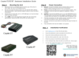
OVERVIEW
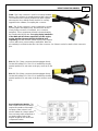
The 30-3813 AEM Infinity Coyote Engine Harness Adapter was designed to run the 2011-2014 Ford 5.0L 4V Ti-
VCT Coyote engines and Ford Racing Crate Engines part numbers M-6007-M50 and M-6007-A50NA; all with
manual transmissions. This is a true standalone system that eliminates the use of the Ford ECU and mass airflow
sensor. The use of this harness makes the kit “plug and play” so no cutting or splicing wires is necessary (when
used with optional 30-3510-00 AUX harness, sold separately). The base configuration files available for the Infinity
EMS are starting points only and will need to be modified for every specific application.
The available Infinity EMS part numbers for this adapter kit are:
· 30-7101 INFINITY 708
· 30-7100 INFINITY 710
Please read this document in its entirety before attempting to start or run an engine.
GETTING STARTED
Refer to the 10-7100 for EMS 30-7100 Infinity Quick Start Guide for additional information on getting
the engine started with the Infinity EMS. The Ford Coyote V8 base session is located in C:
\Documents\AEM\Infinity Tuner\Sessions\Base Sessions.
DOWNLOADABLE FILES
Files can be downloaded from www.aeminfinity.com. An experienced tuner must be available to configure
and manipulate the data before driving can commence. The Quick Start Guide and Full Manual describe
the steps for logging in and registering at www.aeminfinity.com. These documents are available for
download here: http://www.aemelectronics.com/products/support

DOWNLOADABLE FILES
3
© 2017 AEM Performance Electronics
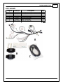
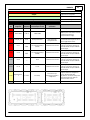
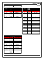
Kit Contents
Diagram
AEM P/N
Description
Qty
A
36-3813
AEM Infinity Coyote Engine Harness Adapter
1
B
35-2840
Ignitor, 4-Channel with Thermal Paste
2
C
35-3014
Cable, USB Comms 9.8'
1
D
4-1008
12-Way Aux Connector, Sealed
1
E
4-1009
Dust Cap, Flash Enable
1
F
4-1010
Jumper, Flash Enable
1
G
1062-20-0122
Socket, Aux Connector
12
10-3813
Instruction Sheet, 30-3813
1

P/N 30-38134
© 2017 AEM Performance Electronics
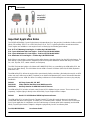
Important Application Notes
The 30-3813 AEM Infinity Coyote Engine Harness Adapter allows for a "plug and play" installation of either an AEM
Infinity 708 or Infinity 710 ECU to a 2011-2014 Ford 5.0L 4V Ti-VCT Coyote Engine with a manual transmission.
These engines are available as crate engines from Ford Racing by the following part numbers:
5.0L 4V Ti-VCT Mustang Crate Engine - Ford Racing P/N M-6007-M50
5.0L Coyote Aluminator NA Crate Engine - Ford Racing P/N M-6007-A50NA
5.0L Coyote Aluminator SC Crate Engine - Ford Racing P/N M-6007-A50SC
5.0L Aluminator XS Crate Engine - Ford Racing P/N M-6007-A50XS
Both of these crate engines come with an engine wiring harness that plugs directly into the AEM wire harness. The
AEM Infinity Coyote Engine Harness Adapter includes a fused power distribution module with relays for radiator
fan, coils, injectors, ECU, starter solenoid, and fuel pump.
The OEM Ford two-wire ignition coils (Motorcraft P/N BR3Z-12029-A) are controlled by the AEM Infinity ECU, but
they are not driven directly. This kit includes the two AEM 4 Channel Coil Drivers (AEM P/N 30-2840) required to
drive these coils.
The AEM Infinity ECU will run the engine with a speed density fueling calculation, eliminating the need for an OEM
airbox and mass airflow sensor (MAF). Required are an intake air temperature (IAT) sensor and manifold absolute
pressure (MAP) sensor. AEM also offers an auxiliary sub-harness to make adding these sensors a plug and play
installation.
30-2010 Air Temp Sensor Kit, 3/8" NPT
30-2130-50 3.5bar (50PSIa) Stainless Steel MAP Sensor Kit
30-3510-00 Auxiliary Harness for AEM MAP and IAT Sensors
The AEM Infinity ECU includes on board control for two UEGO wideband oxygen sensors. These sensors (sold
separately, 2 required) plug in directly to the AEM Infinity Coyote Engine Harness Adapter.
30-2001 Bosch LSU 4.2 Wideband UEGO Replacement Sensor
The AEM Infinity ECU includes Electronic Throttle Control (ETC) that will control the electronic throttle body
included with the above crate engines. A suitable ETC accelerator pedal is required. The base session file for the
Ford Coyote application is configured to use the Ford Mustang accelerator pedal (sold separately) and the AEM
Infinity Coyote Engine Harness Adapter is designed to plug directly into this accelerator pedal.
Ford P/N BR3Z-95836-D Accelerator Pedal

Important Application Notes
5
© 2017 AEM Performance Electronics
The base session file provided for the Ford Coyote application was created with the use of the Ford Racing
Mustang Boss 302 Alternator Kit. The calibration has Lowside 0 duty and frequency tables setup to charge at
~14.7 volts. See "Alternator Control" section for more information on controlling the charging system. The AEM
Infinity Coyote Engine Harness Adapter is designed to plug directly into this alternator.
Ford Racing P/N M-8600-M50BALT Mustang Boss 302 Alternator Kit
The base calibration utilizes the Clutch Position (Neutral Switch) flying lead as an input into the Infinity ECU. Once
grounded, the Infinity ECU provides the ground for the Starter Relay control circuit. If the user wishes not to provide
a ground to this flying lead, follow the steps provided in the "Clutch Position Switch" section to modify the
LS8_Duty [%] table values to allow the starter to be engaged without a clutch signal.
The factory Cylinder Head Temperature sensor and fuel injectors have been fully characterized and their
calibrations are utilized in the base calibration.

P/N 30-38136
© 2017 AEM Performance Electronics
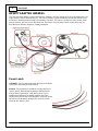
INFINITY ADAPTER HARNESS
The core of the AEM Infinity Coyote Engine Harness Adapter is the main harness that connects between the Ford
engine harness and the AEM Infinity ECU. This harness features a power distribution module that includes fuses
and relays to properly power the engine and related accessories. The harness connections for the various power,
ground, switches, and sensors are described here. The harness may be broken up into several "branches" as
described in the following diagram to simplify installation.
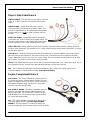
Power Leads
+12V BATT - Two red 10ga main power flying leads should be
connected to the battery positive terminal.
Ground - Two ring terminals should be securely attached to
chassis ground. Remove paint or plating at the attachment
point of these ring terminals. Verify that you have a good
reliable ground path from the battery negative post to the
location being used for these ring terminals. In general, the the
resistance from the battery ground to this chassis location
should be less than 0.1 Ohm.

INFINITY ADAPTER HARNESS
7
© 2017 AEM Performance Electronics
Driver's Side Cabin Branch
IGN SW SOURCE - Red 18ga flying lead should be connected
to the "B" or "BATT" battery source terminal of the ignition
switch.
IGN SW SIGNAL - Orange 18ga flying lead should be
connected to the "IGN" terminal of the ignition switch. This
must be a single terminal on the ignition switch that provides
12V when the key is in both the 'Start' (cranking) and 'Run'
position.
START SW SIGNAL - Orange 18ga flying lead should be
connected to the "START" terminal of the ignition switch. This
must be a single terminal on the ignition switch that provides
12V when the key is in the 'Start' (cranking) position only.
FUEL PUMP +12V - Orange 12ga flying lead should connect to fuel pump positive terminal. Separate ground for
fuel pump must be provided. This provides for ECU control of the fuel pump- running when Engine RPM > 0 and two
second prime at key-on.
CLUTCH POS - Yellow 18ga flying lead should be grounded through a customer-supplied clutch position switch
when the clutch pedal is depressed. The starter solenoid safety lockout function may be bypassed via Infinity
Tuner software if the user chooses not to use a clutch switch. The lead should be insulated and tied up out of the
way if unused. See 'Clutch Position Switch' section for details.
TACHO - Pink 18ga flying lead may be used to drive a standard tachometer with a 12V square wave signal. This is
not a mandatory function, the lead should be insulated and tied up out of the way if unused.
APP - The Accelerator Pedal Position sensor branch terminates with a connector that plugs directly into a
customer-supplied accelerator pedal assembly, Ford P/N BR3Z-95836-D.
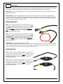
Engine Compartment Branch
PCM 70-WAY - This 70-way terminated connector plugs into
the engine wire harness supplied with the Ford Racing crate
engine. The engine harness side of this connection includes a
white plastic latch that swings over and locks into position
when the connection is fully seated.
AUX INLINE to ENGINE - This 16-way terminated connector
plugs into the engine wire harness supplied with the Ford
Racing crate engine. It is normal for this connector to have
only three wires in it. The remainder of the unused positions
are sealed with blanking plugs.
ALT - This 3-way terminated connector plugs directly into a
customer-supplied alternator, Ford Racing P/N M-8600-
M50BALT. The AEM Infinity ECU controls the voltage set
point of the alternator, see 'Alternator Control' section for details.

P/N 30-38138
© 2017 AEM Performance Electronics
FAN +12V - Orange 12ga flying lead should connect to radiator fan positive terminal. This provides for ECU control
of the electric radiator fan, adjustable on/off temperature configurable via Infinity Tuner Setup Wizard.
FAN -GND - Black 12ga flying lead should connect to radiator fan negative terminal. This wire terminates at the
adjacent ring terminal.
Ring Terminal - Black 12ga lead provides ground to the electric radiator fan. Remove paint or plating at the
attachment point of this ring terminal. Verify that you have a good reliable ground path from the battery negative
post to the location being used for this ring terminal. In general, the the resistance from the battery ground to this
chassis location should be less than 0.1 Ohm.
Exhaust Branch
UEGO 1 - This 6-way terminated connector plugs directly into
a customer-supplied wideband oxygen "UEGO" sensor, AEM
P/N 30-2001. This sensor should be mounted in the exhaust
collector of Bank 1 (cylinders 1-2-3-4), typically passenger
side of the vehicle. Proper cylinder sampling is critical for
closed loop air fuel ratio control.
UEGO 2 - This 6-way terminated connector plugs directly into
a customer-supplied wideband oxygen "UEGO" sensor, AEM
P/N 30-2001. This sensor should be mounted in the exhaust
collector of Bank 2 (cylinders 5-6-7-8), typically driver side of
the vehicle. Proper cylinder sampling is critical for closed loop
air fuel ratio control.
STARTER SOL - Orange 12ga flying lead should be
connected to the starter solenoid. The use of a clutch position switch allows for the use of ECU-controlled starter
solenoid safety lockout function. This function may be bypassed via Infinity Tuner software if the user chooses not
to use a clutch switch. See 'Clutch Position Switch' section for details.
Cabin Branch
Coil 1 - There is a pair of terminated branches marked 'Coil 1'-
one 4-way and one 5-way connector. These connectors should
be plugged into opposite ends of the same 4-Channel Ignitor,
provided in this kit. See '4-Channel Ignitors' section for
mounting requirements.
Coil 2 - There is a pair of terminated branches marked 'Coil 2'-
one 4-way and one 5-way connector. These connectors should
be plugged into opposite ends of the same 4-Channel Ignitor,
provided in this kit. See '4-Channel Ignitors' section for
mounting requirements.

INFINITY ADAPTER HARNESS
9
© 2017 AEM Performance Electronics
Flash - This 2-way connector is used for secondary hardware
flashing. This connector is normally protected with a dust cap.
The included shunt connector jumps the two wires together
when required. Once initially flashed, the EMS is normally
upgraded in the software, not requiring this connector.
AUX - This 12-way connector is used to adapt many common
ancillary inputs and outputs easily. Included in this kit are a
12-way mating connector, 12 terminals, and a connector
wedgelock. These components will need to be terminated by
the installer with 16-22ga wire. For a plug & play installation
of the MAP and IAT sensors required to run this engine,
use the Auxiliary Harness AEM P/N 30-3510-00 (sold
separately). This will allow the installer to plug in the required
sensors with out any custom wiring or termination. Note: the
pin numbering is molded into the wire side of the connector. See 'Pinouts' section for details of this connector's
pins.
ECU C1 - This 73-way connector should be plugged directly
into the AEM Infinity ECU. This ECU is identified by the gray
terminal position lock, and mates to the gray connector on the
ECU.
ECU C2 - This 56-way connector should be plugged directly
into the AEM Infinity ECU. This ECU is identified by the blue
terminal position lock, and mates to the blue connector on the
ECU.
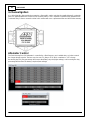
Power Distribution Module - The
PDM contains the fuses and relays
required for operation of the engine,
fuel pump, starter solenoid, and
electric radiator fan. Always replace
fuses and relays with components of
an identical rating. Refer to the
diagram at right for fuse values and
component locations.

P/N 30-381310
© 2017 AEM Performance Electronics
4-Channel Ignitors
It is critical that this driver module be mounted to a flat metallic surface and that the supplied thermally conductive
grease is applied between the module and its mounting surface. This is required to allow the heat generated to be
conducted away. Failure to mount the driver in this manner will cause a premature failure and will void the warranty.
Alternator Control
The Ford Mustang Boss 302 Alternator is controlled by a fixed frequency and a variable duty cycle that controls
the charge voltage set point. The base session sets LS0_Duty to 35 % which correlates to ~14.7v charge.
Decreasing the LS0_Duty percentage will increase the battery set point (higher voltage), and increasing the duty
percentage will decrease the battery set point (lower voltage).

Clutch Position Switch
11
© 2017 AEM Performance Electronics
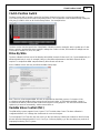
Clutch Position Switch
The base session will not provide a ground for the Starter Solenoid relay unless a ground is provided to the
CLUTCH POS flying lead on the Ford Racing wiring harness. This requirement can be modified through setting the
LS8_Duty [%] table to 100% at all ClutchSwitch positions. See example below:
The base session sets the input for the ‘ClutchSwitch’ 1D table channel to Analog20, which is pulled up to 5 volts.
When a ground is provided this drops Analog20’s voltage from 5 volts to 0 volts, this transition in voltage sets the
ClutchSwitch channel to 0 (OFF) or 1 (ON).
Drive By Wire
The base calibration will set most of the Drive-By-Wire (DBW) channels for the stock 5.0L Coyote throttle body. If a
different throttle body is used, for example Cobra Jet, then further adjustments to the DBW channels will be
required. To complete the DBW setup the Drive By Wire Wizard must be ran.
Select Calibrate sensor data only and follow the DBW Setup steps.
Note: There are a few integrated DBW fail safes incorporated into the Infinity system. For instance, if the
accelerator pedal and throttle position sensors do not track each other, or if the maximum DBW current is
exceeded, there will be a fatal error which will kill the engine for safety purposes. This error will reset when the
ignition key is turned off momentarily, and then turned back on.
Variable Valve Control (VVC)
The AEM Infinity system supports Fords Coyote’s Ti-VCT Variable Valve Control. The base calibration is
configured with base VVC settings that should work for most stock engines.
To ensure proper Ti-VCT function, the user must sync the cam timing by following the instructions listed in Setup
Wizard: Wizards>Setup Wizard>VVC>VVC Cam Sync. Failure to properly sync the cam timing may result in an
improperly functioning Ti-VCT system.

P/N 30-381312
© 2017 AEM Performance Electronics
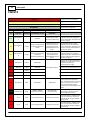
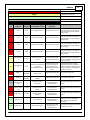
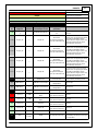
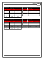
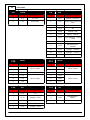
PINOUTS
Dedicated
Dedicated and not reconfigurable
Assigned
Assigned but reconfigurable
Available
Available for user setup
Not Applicable
Not used in this configuration
Required
Required for proper function
Infinity
Pin
Infinity
Assignment
Pin
Destination
AEM Coyote Engine
Harness Adapter Function
Infinity Hardware
Specification
Notes
C1-1
LowsideSwitch_
4
---
Available
Lowside switch, 4A max,
NO internal flyback diode.
'See Setup Wizard Page "LowSide
Assignment Tables" for configuration
options. See 2D table "LS4_Duty [%]" for
activation settings.
C1-2
LowsideSwitch_
5
C3-16
Variable Camshaft Timing
21 Solenoid (Driverside
Intake)
Lowside switch, 4A max
with internal flyback
diode. Inductive load
should NOT have full time
power.
'See Setup Wizard Page "LowSide
Assignment Tables" for configuration
options. See 2D table "LS5_Duty [%]" for
activation settings. See Setup Wizard
page 'VVC' for options.
C1-3
LowsideSwitch_
6
C3-56
Variable Camshaft Timing
12 Solenoid
(Passengerside Exhaust)
Lowside switch, 4A max
with internal flyback
diode. Inductive load
should NOT have full time
power.
'See Setup Wizard Page "LowSide
Assignment Tables" for configuration
options. See 2D table "LS6_Duty [%]" for
activation settings. See Setup Wizard
page 'VVC' for options.
C1-4
UEGO 1 Heat
C10-4
UEGO 1 Heat
Bosch UEGO controller
Connect to pin 4 of Bosch UEGO sensor.
NOTE that pin 3 of the Sensor is heater
(+) and must be power by a
fused/switched 12V supply.
C1-5
UEGO 1 IA
C10-2
UEGO 1 IA
Connect to pin 2 of Bosch UEGO sensor
C1-6
UEGO 1 IP
C10-6
UEGO 1 IP
Connect to pin 6 of Bosch UEGO sensor
C1-7
UEGO 1 UN
C10-1
UEGO 1 UN
Connect to pin 1 of Bosch UEGO sensor
C1-8
UEGO 1 VM
C10-5
UEGO 1 VM
Connect to pin 5 of Bosch UEGO sensor.
C1-9
Flash_Enable
C8-2
Flash Enable
10K pulldown
Not usually needed for automatic
firmware updates through Infinity
Tuner. If connection errors occur during
update, connect 12 volts to this pin
before proceeding with upgrade.
Disconnect the 12 volts signal after the
update.
C1-10
+12V_R8C_CPU
P1-9
KAPWR / 12VHAAT
Permanent +12V Power
Dedicated power
management CPU
Full time battery power. MUST be
powered before the ignition switch
input is triggered (See C1-65).
C1-11
Coil 4
C4-5
Coil on Plug Assembly 4
25 mA max source current
0-5V Falling edge fire. DO NOT connect
directly to coil primary. Must use an
ignitor OR CDI that accepts a FALLING
edge fire signal.
C1-12
Coil 3
C4-4
Coil on Plug Assembly 3
25 mA max source current
0-5V Falling edge fire. DO NOT connect
directly to coil primary. Must use an
ignitor OR CDI that accepts a FALLING
edge fire signal.

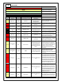
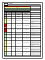
PINOUTS
13
© 2017 AEM Performance Electronics
Dedicated
Dedicated and not reconfigurable
Assigned
Assigned but reconfigurable
Available
Available for user setup
Not Applicable
Not used in this configuration
Required
Required for proper function
Infinity
Pin
Infinity
Assignment
Pin
Destination
AEM Coyote Engine
Harness Adapter Function
Infinity Hardware
Specification
Notes
C1-13
Coil 2
C4-2
Coil on Plug Assembly 2
25 mA max source current
0-5V Falling edge fire. DO NOT connect
directly to coil primary. Must use an
ignitor OR CDI that accepts a FALLING
edge fire signal.
C1-14
Coil 1
C4-1
Coil on Plug Assembly 1
25 mA max source current
0-5V Falling edge fire. DO NOT connect
directly to coil primary. Must use an
ignitor OR CDI that accepts a FALLING
edge fire signal.
C1-15
Coil 6
C6-2
Coil on Plug Assembly 6
25 mA max source current
0-5V Falling edge fire. DO NOT connect
directly to coil primary. Must use an
ignitor OR CDI that accepts a FALLING
edge fire signal.
C1-16
Coil 5
C6-1
Coil on Plug Assembly 5
25 mA max source current
0-5V Falling edge fire. DO NOT connect
directly to coil primary. Must use an
ignitor OR CDI that accepts a FALLING
edge fire signal.
C1-17
LowsideSwitch_
2
P1-14
Radiator Fan Relay
Control
Lowside switch, 4A max,
NO internal flyback diode.
See Setup Wizard Page "LowSide
Assignment Tables" for configuration
options. See 2D table "LS5_Duty [%]" for
activation settings.
C1-18
LowsideSwitch_
3
C3-2
Variable Camshaft Timing
11 Solenoid
(Passengerside Intake)
Lowside switch, 4A max
with internal flyback
diode. Inductive load
should NOT have full time
power.
'See Setup Wizard Page "LowSide
Assignment Tables" for configuration
options. See 2D table "LS3_Duty [%]" for
activation settings. See Setup Wizard
page 'VVC' for options.
C1-19
AGND_1
SP1
(AGND)
APP
Sensor Ground
Dedicated analog ground
Analog 0-5V sensor ground
C1-20
AGND_1
SP2
(AGND)
Digital Cams Ground (E-
SIGRTN)
Dedicated analog ground
Analog 0-5V sensor ground
C1-21
Crankshaft
Position Sensor
Hall
---
Crankshaft Position
Sensor Hall
10K pullup to 12V. Will
work with ground or
floating switches.
See Setup Wizard page 'Cam/Crank' for
options.
C1-22
Camshaft
Position Sensor
1 Hall
C3-41
Camshaft Position Bank 1
(Passenger Intake)
(CMP11)
10K pullup to 12V. Will
work with ground or
floating switches.
See Setup Wizard page 'Cam/Crank' for
options.
C1-23
Digital_In_2
C3-42
Camshaft Position Bank 2
(Driverside Intake)
(CMP21)
10K pullup to 12V. Will
work with ground or
floating switches.
See Setup Wizard page 'Cam/Crank' for
options.
C1-24
Digital_In_3
---
Turbo Speed Hz
10K pullup to 12V. Will
work with ground or
floating switches.
See Setup Wizard page 'Turbo Speed' for
calibration constant. TurboSpeed
[RPM] = Turbo [Hz] * Turbo Speed
Calibration.
C1-25
Digital_In_4
---
Vehicle Speed Sensor
10K pullup to 12V. Will
work with ground or
floating switches.
See Setup Wizard page 'Vehicle Speed'
for calibration constant.

P/N 30-381314
© 2017 AEM Performance Electronics
Dedicated
Dedicated and not reconfigurable
Assigned
Assigned but reconfigurable
Available
Available for user setup
Not Applicable
Not used in this configuration
Required
Required for proper function
Infinity
Pin
Infinity
Assignment
Pin
Destination
AEM Coyote Engine
Harness Adapter Function
Infinity Hardware
Specification
Notes
C1-26
Digital_In_5
C9-6
Flex Fuel
10K pullup to 12V. Will
work with ground or
floating switches.
See channel FlexDigitalIn [Hz] for raw
frequency input data.
C1-27
Knock Sensor 1
C3-7
Knock Sensor+ [KS1+]
Dedicated knock signal
processor
See Setup Wizard page 'Knock Setup' for
options.
C1-28
Knock Sensor 2
C3-45
Knock Sensor+ [KS2+]
Dedicated knock signal
processor
See Setup Wizard page 'Knock Setup' for
options.
C1-29
+12V_Relay_Con
trol
P1-18
PCM Relay control
0.7A max ground sink for
external relay control
Will activate at key on and at key off
according to the configuration settings.
C1-30
Power Ground
C14-4
Shield Drain
Power Ground
Connect directly to battery ground
C1-31
CANL_Aout
C14-2
AEMNet CANL
Dedicated High Speed CAN
Transceiver
Recommend twisted pair (one twist per
2") with terminating resistor. Contact
AEM for additional information.
C1-32
CANH_Aout
C14-1
AEMNet CANH
Dedicated High Speed CAN
Transceiver
Recommend twisted pair (one twist per
2") with terminating resistor. Contact
AEM for additional information.
C1-33
LowsideSwitch_
1
C9-7
Boost Control
Lowside switch, 4A max
with internal flyback
diode. Inductive load
should NOT have full time
power.
See Setup Wizard Page "LowSide
Assignment Tables" for configuration
options. See 2D table "LS1_Duty [%]" for
activation settings. See Setup Wizard
page 'Boost Control' for options.
Monitor BoostControl [%] channel for
output state.
C1-34
LowsideSwitch_
0
C13-2
GENRC
Lowside switch, 4A max,
NO internal flyback diode.
See Setup Wizard Page "LowSide
Assignment Tables" for output
assignment and 2D table "LS0_Duty [%]"
for activation.
C1-35
Analog_In_7
C3-39
DBW Negative Slope (TP1)
12 bit A/D, 100K pullup to
5V
0-5V analog signal. Use +5V Out pins as
power supply and Sensor Ground pins
as the low reference. Do not connect
signals referenced to +12V as this can
permanently damage the ECU. See the
Setup Wizard Set Throttle Range page
for automatic min/max calibration.
Monitor the Throttle [%] channel. Also
DB1_TPSA [%] for DBW applications.
C1-36
Analog_In_8
C9-5
MAP Sensor
12 bit A/D, 100K pullup to
5V
0-5V analog signal. Use +5V Out pins as
power supply and Sensor Ground pins
as the low reference. Do not connect
signals referenced to +12V as this can
permanently damage the ECU. See the
Setup Wizard Set Manifold Pressure
page for setup and calibration. Monitor
the MAP [kPa] channel.
C1-37
Analog_In_9
C9-1
Fuel Pressure
12 bit A/D, 100K pullup to
5V
0-5V analog signal. Use +5V Out pins as
power supply and Sensor Ground pins
as the low reference. Do not connect

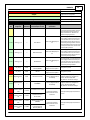
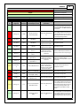
PINOUTS
15
© 2017 AEM Performance Electronics
Dedicated
Dedicated and not reconfigurable
Assigned
Assigned but reconfigurable
Available
Available for user setup
Not Applicable
Not used in this configuration
Required
Required for proper function
Infinity
Pin
Infinity
Assignment
Pin
Destination
AEM Coyote Engine
Harness Adapter Function
Infinity Hardware
Specification
Notes
signals referenced to +12V as this can
permanently damage the ECU. See the
Setup Wizard Fuel Pressure page for
setup and calibration. Monitor the
FuelPressure [psig] channel.
C1-38
Analog_In_10
---
Baro Sensor
12 bit A/D, 100K pullup to
5V
0-5V analog signal. Use +5V Out pins as
power supply and Sensor Ground pins
as the low reference. Do not connect
signals referenced to +12V as this can
permanently damage the ECU. See the
Setup Wizard Barometric Pressure page
for setup and calibration. Monitor the
BaroPress [kPa] channel.
C1-39
Analog_In_11
---
Shift Switch Input
12 bit A/D, 100K pullup to
5V
0-5V analog signal. Use +5V Out pins as
power supply and Sensor Ground pins
as the low reference. Do not connect
signals referenced to +12V as this can
permanently damage the ECU.
C1-40
Analog_In_12
---
Mode Switch
12 bit A/D, 100K pullup to
5V
0-5V analog signal. Use +5V Out pins as
power supply and Sensor Ground pins
as the low reference. Do not connect
signals referenced to +12V as this can
permanently damage the ECU.
C1-41
+5V_Out_1
C3-9
Electronic Throttle
Control (ETCREF)
Regulated, fused +5V
supply for sensor power
Analog sensor power
C1-42
+5V_Out_1
C9-4
+5V Out
Regulated, fused +5V
supply for sensor power
Analog sensor power
C1-43
HighsideSwitch_
1
C9-9
HS1 (switched 12V)
0.7A max, High Side Solid
State Relay
See Setup Wizard page 'HighSide
Assigment Tables' for configuration
options. See 2D lookup table
'HS1_Table' for activation settings.
C1-44
HighsideSwitch_
0
---
Available
0.7A max, High Side Solid
State Relay
See Setup Wizard page 'HighSide
Assigment Tables' for configuration
options. See 2D lookup table
'HS0_Table' for activation settings.
C1-45
Crankshaft
Position Sensor
VR+
C3-13
Crankshaft Position (CKP+)
Differential Variable
Reluctance Zero Cross
Detection
See Setup Wizard page 'Cam/Crank' for
options.
C1-46
Crankshaft
Position Sensor
VR-
C3-12
Crankshaft Position
Sensor (CKP-)
C1-47
Camshaft
Position Sensor
1 VR-
C3-29
VR Reluctance Sensor
(VRSRTN)
Differential Variable
Reluctance Zero Cross
Detection
See Setup Wizard page 'Cam/Crank' for
options.
C1-48
Camshaft
Position Sensor
1 VR+
C3-46
Camshaft Position Bank 1
In (Passengerside
Exhaust) (CMP12)

P/N 30-381316
© 2017 AEM Performance Electronics
Dedicated
Dedicated and not reconfigurable
Assigned
Assigned but reconfigurable
Available
Available for user setup
Not Applicable
Not used in this configuration
Required
Required for proper function
Infinity
Pin
Infinity
Assignment
Pin
Destination
AEM Coyote Engine
Harness Adapter Function
Infinity Hardware
Specification
Notes
C1-49
VR+_In_2
C3-47
Camshaft Position Bank 2
In (Driverside Exhaust)
(CMP22)
Differential Variable
Reluctance Zero Cross
Detection
See Setup Wizard page 'Cam/Crank' for
options.
C1-50
VR-_In_2
C3-48
Variable Reluctance
Sensor (VRSRTN2)
C1-51
VR-_In_3
---
Driven Left Wheel Speed
Sensor -
Differential Variable
Reluctance Zero Cross
Detection
See 'Driven Wheel Speed Calibration' in
the Setup Wizard 'Vehicle Speed' page.
C1-52
VR+_In_3
---
Driven Left Wheel Speed
Sensor +
C1-53
DBW1 Motor -
C3-67
Throttle Actuator Control
Motor (TACM-)
5.0A max Throttle Control
Hbridge Drive
+12V to close
C1-54
DBW1 Motor +
C3-68
Throttle Actuator Control
Motor (TACM+)
5.0A max Throttle Control
Hbridge Drive
+12V to open
C1-55
Power Ground
SP3
(PGND)
Crankshaft Position
Sensor Shield (SHDRTN)
Power Ground
Connect directly to battery ground
C1-56
Injector 6
C3-64
Fuel Injector Driver 6
(INJ6)
Saturated or peak and
hold, 3A max continuous
Injector 6
C1-57
Injector 5
C3-63
Fuel Injector Driver 5
(INJ5)
Saturated or peak and
hold, 3A max continuous
Injector 5
C1-58
Injector 4
C3-62
Fuel Injector Driver 4
(INJ4)
Saturated or peak and
hold, 3A max continuous
Injector 4
C1-59
Injector 3
C3-55
Fuel Injector Driver 3
(INJ3)
Saturated or peak and
hold, 3A max continuous
Injector 3
C1-60
Power Ground
R2
PWR Ground
Power Ground
Connect directly to battery ground
C1-61
+12V
P1-6
Injector and Digital Cam
Sensor +12V Power
12 volt power from relay
12 volt power from relay. Relay must be
controlled by +12V Relay Control signal,
pin C1-29 above.
C1-62
Injector 2
C3-54
Fuel Injector Driver 2
(INJ2)
Saturated or peak and
hold, 3A max continuous
Injector 2
C1-63
Injector 1
C3-53
Fuel Injector Driver 1
(INJ1)
Saturated or peak and
hold, 3A max continuous
Injector 1
C1-64
+12V
---
+12V In
12 volt power from relay
12 volt power from relay. Relay must be
controlled by +12V Relay Control signal
pin C1-29 above.
C1-65
+12V_SW
F2
12V Start & Run (ISP-R)
Blunt Lead
10K pulldown
Full time battery power must be
available at C1-10 before this input is
triggered.
C1-66
Analog_In_Temp
_1
C3-30
Cylinder Head
Temperature (CHT)
12 bit A/D, 2.49K pullup to
5V
See 'Coolant Temperature' Setup
Wizard for selection.
C1-67
Analog_In_Temp
_2
C9-2
Intake Air Temperature
12 bit A/D, 2.49K pullup to
5V
See 'Air Temperature' Setup Wizard for
selection.

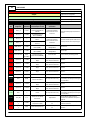
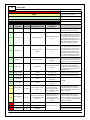
PINOUTS
17
© 2017 AEM Performance Electronics
Dedicated
Dedicated and not reconfigurable
Assigned
Assigned but reconfigurable
Available
Available for user setup
Not Applicable
Not used in this configuration
Required
Required for proper function
Infinity
Pin
Infinity
Assignment
Pin
Destination
AEM Coyote Engine
Harness Adapter Function
Infinity Hardware
Specification
Notes
C1-68
Analog_In_Temp
_3
---
Oil Temperature Sensor
12 bit A/D, 2.49K pullup to
5V
See 'Oil Temperature' Setup Wizard for
selection.
C1-69
Stepper_2A
---
Stepper 2A
Automotive,
Programmable Stepper
Driver, up to 28V and ±1.4A
Be sure that each internal coil of the
stepper motor are properly paired with
the 1A/1B and 2A/2B ECU outputs.
Supports Bi-Polar stepper motors only.
See Setup Wizard page 'Idle - Show
Advanced Setup' for options.
C1-70
Stepper_1A
---
Stepper 1A
Automotive,
Programmable Stepper
Driver, up to 28V and ±1.4A
Be sure that each internal coil of the
stepper motor are properly paired with
the 1A/1B and 2A/2B ECU outputs.
Supports Bi-Polar stepper motors only.
See Setup Wizard page 'Idle - Show
Advanced Setup' for options.
C1-71
Stepper_2B
---
Stepper 2B
Automotive,
Programmable Stepper
Driver, up to 28V and ±1.4A
Be sure that each internal coil of the
stepper motor are properly paired with
the 1A/1B and 2A/2B ECU outputs.
Supports Bi-Polar stepper motors only.
See Setup Wizard page 'Idle - Show
Advanced Setup' for options.
C1-72
Stepper_1B
---
Stepper 1B
Automotive,
Programmable Stepper
Driver, up to 28V and ±1.4A
Be sure that each internal coil of the
stepper motor are properly paired with
the 1A/1B and 2A/2B ECU outputs.
Supports Bi-Polar stepper motors only.
See Setup Wizard page 'Idle - Show
Advanced Setup' for options.
C1-73
Power Ground
R2
PWR Ground
Power Ground
Connect directly to battery ground
C2-1
DBW2 Motor +
---
DBW Motor Control Open
5.0A max Throttle Control
Hbridge Drive
+12V to open
C2-2
DBW2 Motor -
---
DBW Motor Control Close
5.0A max Throttle Control
Hbridge Drive
+12V to close
C2-3
Power Ground
R2
Ground
Power Ground
Connect directly to battery ground
C2-4
Injector 7
C3-65
Fuel Injector Driver 7
(INJ7)
Saturated or peak and
hold, 3A max continuous
Injector 7
C2-5
Injector 8
C3-66
Fuel Injector Driver 8
(INJ8)
Saturated or peak and
hold, 3A max continuous
Injector 8
C2-6
Injector 9
---
Injector 9
Saturated or peak and
hold, 3A max continuous
Injector 9
C2-7
Injector 10
---
Injector 10
Saturated or peak and
hold, 3A max continuous
Injector 10
C2-8
Power Ground
---
Available
Power Ground
Connect directly to battery ground
C2-9
+12V
P1-19
VPWR
12 volt power from relay
12 volt power from relay. Relay must be
controlled by +12V Relay Control signal,
pin C1-29 above.

P/N 30-381318
© 2017 AEM Performance Electronics
Dedicated
Dedicated and not reconfigurable
Assigned
Assigned but reconfigurable
Available
Available for user setup
Not Applicable
Not used in this configuration
Required
Required for proper function
Infinity
Pin
Infinity
Assignment
Pin
Destination
AEM Coyote Engine
Harness Adapter Function
Infinity Hardware
Specification
Notes
C2-10
Injector 11
---
Injector 11
Saturated or peak and
hold, 3A max continuous
Not used
C2-11
Injector 12
---
Injector 12
Saturated or peak and
hold, 3A max continuous
Not used
C2-12
Analog_In_17
C9-10
Mode Switch Input
12 bit A/D, 100K pullup to
5V
0-5V analog signal. Use +5V Out pins as
power supply and Sensor Ground pins
as the low reference. Do not connect
signals referenced to +12V as this can
permanently damage the ECU. See
Setup Wizard 'Input Functions' page for
input selection.
C2-13
Analog_In_18
C12-2
DBW_APP1 [%]
12 bit A/D, 100K pullup to
5V
0-5V analog signal. Use +5V Out pins as
power supply and Sensor Ground pins
as the low reference. Do not connect
signals referenced to +12V as this can
permanently damage the ECU.
C2-14
Analog_In_19
C12-5
DBW_APP2 [%]
12 bit A/D, 100K pullup to
5V
0-5V analog signal. Use +5V Out pins as
power supply and Sensor Ground pins
as the low reference. Do not connect
signals referenced to +12V as this can
permanently damage the ECU.
C2-15
Analog_In_Temp
_4
---
Charge Out Temperature
12 bit A/D, 2.49K pullup to
5V
See ChargeOutTemp [C] table for
calibration data and ChargeOutTemp
[C] for channel data.
C2-16
Analog_In_Temp
_5
---
Airbox Temperature
12 bit A/D, 2.49K pullup to
5V
See AirboxTemp [C] table for calibration
data and AirboxTemp [C] for channel
data.
C2-17
Analog_In_Temp
_6
---
Trans Temperature
12 bit A/D, 2.49K pullup to
5V
See TransTemp [C] table for calibration
data and TransTemp [C] for channel
data.
C2-18
Analog_In_13
C9-11
Oil Pressure
12 bit A/D, 100K pullup to
5V
0-5V analog signal. Use +5V Out pins as
power supply and Sensor Ground pins
as the low reference. Do not connect
signals referenced to +12V as this can
permanently damage the ECU. See
Setup Wizard 'Oil Pressure' page for
setup options. See OilPressure [psig]
for channel data.
C2-19
Analog_In_14
C9-12
Traction Control Mode /
Sensitivity
12 bit A/D, 100K pullup to
5V
0-5V analog signal. Use +5V Out pins as
power supply and Sensor Ground pins
as the low reference. Do not connect
signals referenced to +12V as this can
permanently damage the ECU. See the
TC_SlipTrgtTrim [MPH] 1-axis table.
C2-20
Analog_In_15
---
Exhaust Back Pressure
12 bit A/D, 100K pullup to
5V
0-5V analog signal. Use +5V Out pins as
power supply and Sensor Ground pins
as the low reference. Do not connect
signals referenced to +12V as this can

PINOUTS
19
© 2017 AEM Performance Electronics
Dedicated
Dedicated and not reconfigurable
Assigned
Assigned but reconfigurable
Available
Available for user setup
Not Applicable
Not used in this configuration
Required
Required for proper function
Infinity
Pin
Infinity
Assignment
Pin
Destination
AEM Coyote Engine
Harness Adapter Function
Infinity Hardware
Specification
Notes
permanently damage the ECU. See
Setup Wizard 'Exhaust Pressure' page
for setup options. See EBPress [kPa] for
channel data.
C2-21
Analog_In_16
C3-10
Throttle Position #
Positive Slope (TP2)
12 bit A/D, 100K pullup to
5V
0-5V analog signal. Use +5V Out pins as
power supply and Sensor Ground pins
as the low reference. Do not connect
signals referenced to +12V as this can
permanently damage the ECU.
C2-22
+5V_Out_2
C12-1
APPVREF (1)
Regulated, fused +5V
supply for sensor power
Analog sensor power
C2-23
+5V_Out_2
C12-6
APPVREF (2)
Regulated, fused +5V
supply for sensor power
Analog sensor power
C2-24
+5V_Out_2
---
+5V Out
Regulated, fused +5V
supply for sensor power
Analog sensor power
C2-25
VR+_In_5
---
Driven Right Wheel Speed
Sensor +
Differential Variable
Reluctance Zero Cross
Detection
See Driven Wheel Speed Calibration in
the Setup Wizard 'Vehicle Speed' page.
C2-26
VR-_In_5
---
Driven Right Wheel Speed
Sensor -
C2-27
VR-_In_4
---
Non Driven Right Wheel
Speed Sensor -
Differential Variable
Reluctance Zero Cross
Detection
See Non Driven Wheel Speed
Calibration in the Setup Wizard 'Vehicle
Speed' page.
C2-28
V R+_In_4
---
Non Driven Right Wheel
Speed Sensor +
C2-29
LowsideSwitch_
9
F8
Tacho (CTO) Blunt Lead
Lowside switch, 4A max
with internal flyback
diode, 2.2K 12V pullup.
Inductive load should NOT
have full time power.
See Setup Wizard page 'Tacho' for
configuration options.
C2-30
AGND_2
C3-32
DBW Ground (ETCRTN)
Dedicated analog ground
Analog 0-5V sensor ground
C2-31
AGND_2
C9-3
Knock Sensor 1 & 2
Ground [KS1 - & KS2 -]
Dedicated analog ground
Analog 0-5V sensor ground
C2-32
AGND_2
C3-8
APP Sensor 1 & 2 Ground
APPRTN (1) & (2)
Dedicated analog ground
Analog 0-5V sensor ground
C2-33
Analog_In_20
F9
Clutch Position (Neutral
Switch) Blunt Lead
12 bit A/D, 100K pullup to
5V
0-5V analog signal. Use +5V Out pins as
power supply and Sensor Ground pins
as the low reference. Do not connect
signals referenced to +12V as this can
permanently damage the ECU. 'See
ClutchSwitch 1-axis table for setup
options.
C2-34
Analog_In_21
---
3 Step Enable Switch /
TPS2A
12 bit A/D, 100K pullup to
5V
0-5V analog signal. Use +5V Out pins as
power supply and Sensor Ground pins
as the low reference. Do not connect
signals referenced to +12V as this can

P/N 30-381320
© 2017 AEM Performance Electronics
Dedicated
Dedicated and not reconfigurable
Assigned
Assigned but reconfigurable
Available
Available for user setup
Not Applicable
Not used in this configuration
Required
Required for proper function
Infinity
Pin
Infinity
Assignment
Pin
Destination
AEM Coyote Engine
Harness Adapter Function
Infinity Hardware
Specification
Notes
permanently damage the ECU. See
3StepSwitch 1-axis table for setup.
C2-35
Analog_In_22
---
USB Logging Activate
12 bit A/D, 100K pullup to
5V
0-5V analog signal. Use +5V Out pins as
power supply and Sensor Ground pins
as the low reference. Do not connect
signals referenced to +12V as this can
permanently damage the ECU. See
USBLoggingRequestIn channel for input
state. See Setup Wizard page 'USB
Logging' for configuration options.
C2-36
Analog_In_23
---
Charge Out Pressure /
TPS2B
12 bit A/D, 100K pullup to
5V
0-5V analog signal. Use +5V Out pins as
power supply and Sensor Ground pins
as the low reference. Do not connect
signals referenced to +12V as this can
permanently damage the ECU. See
ChargeOutPress [kPa] channel for input
state. See Setup Wizard page 'Charge
Out Pressure' for calibration options.
C2-37
Digital_In_6
---
Spare Digital Input
No pullup. Will work with
TTL signals.
Input can be assigned to different pins.
See Setup Wizard page Input Function
Assignments for input mapping options.
C2-38
Digital_In_7
---
Brake Switch
No pullup. Will work with
TTL signals.
See BrakeSwitch 1-axis table for setup
options. Input can be assigned to
different pins. See Setup Wizard page
'Input Function Assignments' for input
mapping options.
C2-39
Power Ground
---
Ground
Power Ground
Connect directly to battery ground
C2-40
Power Ground
---
Ground
Power Ground
Connect directly to battery ground
C2-41
CanH_Bout
---
CANH
Dedicated High Speed CAN
Transceiver
Ford EPAS
C2-42
CanL_Bout
---
CANL
Dedicated High Speed CAN
Transceiver
C2-43
LowsideSwitch_
8
P1-36
Starter Motor Control
(SMC)
Lowside switch, 4A max
with internal flyback
diode. Inductive load
should NOT have full time
power.
See Setup Wizard Page "LowSide
Assignment Tables" for configuration
options. See 2D table "LS8_Duty [%]" for
activation settings.
C2-44
LowsideSwitch_
7
C3-57
Variable Camshaft Timing
22 Solenoid (Driverside
Exhaust)
Lowside switch, 4A max
with internal flyback
diode. Inductive load
should NOT have full time
power.
'See Setup Wizard Page "LowSide
Assignment Tables" for configuration
options. See 2D table "LS7_Duty [%]" for
activation settings. See Setup Wizard
page 'VVC' for options.
C2-45
UEGO 2 VM
C11-5
UEGO 2 VM
Bosch UEGO Controller
Connect to pin 5 of Bosch UEGO sensor.
C2-46
UEGO 2 UN
C11-1
UEGO 2 UN
Connect to pin 1 of Bosch UEGO sensor
C2-47
UEGO 2 IP
C11-6
UEGO 2 IP
Connect to pin 6 of Bosch UEGO sensor
Page is loading ...
Page is loading ...
Page is loading ...
Page is loading ...
Page is loading ...
Page is loading ...
-
 1
1
-
 2
2
-
 3
3
-
 4
4
-
 5
5
-
 6
6
-
 7
7
-
 8
8
-
 9
9
-
 10
10
-
 11
11
-
 12
12
-
 13
13
-
 14
14
-
 15
15
-
 16
16
-
 17
17
-
 18
18
-
 19
19
-
 20
20
-
 21
21
-
 22
22
-
 23
23
-
 24
24
-
 25
25
-
 26
26


Ask a question and I''ll find the answer in the document
Finding information in a document is now easier with AI
Related papers
-
AEM 30-3702 Operating instructions
-
-
-
-
-
-
-
-
AEM 30-2061 Operating instructions
-
Other documents
-
Ford 2018 Mustang User manual
-
 Track Your Truck Coyote AT Hardware Installation Manual
-
Powerplus PP-MUSTANG Datasheet
-
Edelbrock Pro-Flo 4+ EFI Engine Management System #36160-bundle for 2015-17 Ford Coyote Installation guide
-
-
Holley EFI 554-112 Operating instructions
-
PAC SWI-X Tech Brief
-
DW 300c Fuel Pump DeatschWerks Installation guide
-
 AEM Filters 21-8316DS Installation guide
-
Coyote CBIRL Owner's manual

