Page is loading ...

Tankless Water
Heater Kit
Installation Guide
Model:3006
WARNING: Drain Valves should remain closed during normal operation. The valves are not
designed for installation exposed to subfreezing or extreme weather conditions

Installation Instructions
Inspection and Set-up
Check Valve set complete with the following:
- Cold Water Valve
- Hot Water Valve
- Pressure Relief Valve
1.Use and Installation Manual
a) Remove tank-less from packaging and inspect contents
b) Carefully position tank-less unit front face-up on floor or
blocks in a stable location for valve installation
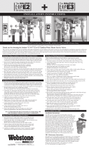
2.Installing the valve set
a) Begin with applying approved thread sealant and/or Teflon
tape to the male threads on your tank-less unit
b) Next remove the hot water valve from packaging and hand
thread pipe nipple into the valve outlet
c) Use the pipe nipple as a handle and rotate valve handle a
couple of times to exercise it before installing
d) Gently thread hot water valve onto hot outlet of tank-less
heater, position of valve should face handle away from tank-
less unit when in the “Run” Position/ wrench tighten

carefully using a back-up wrench to protect the outlet on the
tank-less unit
e) On the final turn of your wrench position the handle at a
slight angle past center of facing forward from the unit
f) Next remove the cold water valve from the packaging and
hand thread a pipe nipple into the valve inlet
g) Use the pipe nipple as handle and rotate the valve handle a
couple times to exercise it before installing
h) Gently thread cold water valve onto cold inlet of tank-less
heater, position of valve should face handle away from tank-
less unit when in the “Run” position/ wrench tighten
carefully using a back-up wrench to protect the outlet on the
tank-less unit
i) On the final turn of your wrench position the handle at a
slight angle past center of facing forward from the unit
3.Installing the Pressure Relief Valve (PRV)
a) Apply approved thread sealant and/or Teflon Tape to the
male threads on the relief valve
b) Gently thread relief valve into open port opposite hose
thread on hot water valve/ wrench tighten and position valve
for connection to drain line

Pressure Relief Valve (PRV)
Installation instructions:
• The PRV must be connected by the threaded connection
opposite the wing handle on the hot water valve (designated
by the RED Drain handle) or the threaded connection on the
side of the relocation fitting above the hot water valve.
• Installation must maintain a ¾ port size with no shut off
valve or line restriction in-between the appliance and the
PRV. The discharge line from the PRV should pitch downward
and terminate 6” above drains where discharge will be
clearly visible. The discharge end of the line shall be plain
(unthreaded) and a minimum of ¾” in diameter. The
discharge line material must be suitable for water at least
180°Fahrenheit and can be no more than 30 feet in length
and contain no more than 4 elbows or bends. No valve of any
type may be installed in the discharge line of the pressure
relief valve.
/


