Hinkley Lighting 15452BZ Operating instructions

Type
Operating instructions

This manual is also suitable for

Hinkley Lighting 15452BZ is a low-voltage sign light designed to be mounted on a wall or ceiling. It comes with two extension tubes, one 3 inches long and the other 6 inches long, so you can choose the length that best fits your needs. The light has a constant voltage LED driver and is designed to be operated with Hinkley approved LED drivers. Connecting the LED to a standard 120-volt supply without using the driver will result in failure of the LEDs. The light also has a retaining nut on the backside of the mounting plate that allows you to easily replace the extension tube if needed.

Hinkley Lighting 15452BZ is a low-voltage sign light designed to be mounted on a wall or ceiling. It comes with two extension tubes, one 3 inches long and the other 6 inches long, so you can choose the length that best fits your needs. The light has a constant voltage LED driver and is designed to be operated with Hinkley approved LED drivers. Connecting the LED to a standard 120-volt supply without using the driver will result in failure of the LEDs. The light also has a retaining nut on the backside of the mounting plate that allows you to easily replace the extension tube if needed.

I.S. 155 Nexus Sign Light
Mounting Instructions
Item No: 15450, 15452
Start Here
SAFETY WARNING: TURN POWER SUPPLY OFF DURING INSTALLATION. IF
NEW WIRING IS REQUIRED, CONSULT A QUALIFIED ELECTRICIAN OR
LOCAL AUTHORITY FOR CODE REQUIREMENTS.
IMPORTANT OPERATION NOTE: THIS LIMINAIRE IS DESIGNED TO BE
OPERATED WITH HINKLEY APPROVED LED DRIVERS. CONNECTING LED TO
STANDARD INCOMIMG 120VOLT SUPPLY WITHOUT THE USE OF THE DRIVER
WILL RESULT IN FAILURE OF LEDS
1. Find a clear area to work.
2. Unpack xture from carton.
3. Carefully review instructions prior to assembly.
Electrical Connections:
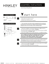
1. The xture is supplied with a constant voltage LED driver (A). Feed Fixture
wires through Extension Tube (B) and Mounting Plate (C).
Driver Wire: (2) red wires connect to the xture wire and black and white
wires conncet to supply wire.
Fixture Wire: (4) Black wires from light = (2) wires (-) negative and (2) wires (+)
positive. **One (-) negative and one (+) positive for each light bar
Connect the 2 wires with labels to one red wire on driver and other 2 without
labels to the other red wire on driver.
The other set of Black and White wires are to be connected to the Incoming
Black and White supply wires. The driver is designed to “Float” inside the
junction box.
Fixture Mounting:
1. Make electrical connections according Electrical Connections above.
2. Attach the Fixture (D) to the Extension tube (B) by turning it onto the
threaded stem that is attached to the xture.
3. Holes in Mounting Plate (C) should line up with mounting ears on junction
box. Using screws supplied with junction box attach mounting plate. Tighten
screws until snug.
4. It is important to seal the joint between the mounting plate and the
mounting surface with the appropriately rated silicone for the surface being
applied to.
Extension Tube Replacement :
Your xture is supplied with two Extension tubes. One is 3 inches long and
the other one is 6 inches long. If you want to
use the shorter or the longer
tube you will need to remove the retaining nut (E) on the backside of the
Mounting plate and then replace the existing tube.
Low Voltage Wire Replacement:
Low voltage wire can be purchased through Hinkley’s website or contacting
our customer care department.
Electrical Connections
(A) LED
Driver
(C) Mounting
Plate
(B) Extension
Tube
Fixture Mounting
Mounting screws
(supplied with
Junction Box)
Extension Tube Replacement
(E) Retaining
Nut
(B) Extension
Tube
I.S. 155 Luz de la señal del nexo
Instrucciones de montaje
English Item No: 15450, 15452 Spanish
Empieza aqui
ADVERTENCIA DE SEGURIDAD: APAGUE LA ALIMENTACIÓN DURANTE
LA INSTALACIÓN. SI SE REQUIERE NUEVO CABLEADO, CONSULTE A UN
ELECTRICISTA CALIFICADO O AUTORIDAD LOCAL PARA REQUISITOS DE
CÓDIGO.
FUNCIONAMIENTO IMPORTANTE NOTA: ESTE LIMINAIRE ESTÁ DISEÑADO
PARA SER OPERADO CON LOS CONDUCTORES DEL LED HINKLEY APROBADOS.
CONECTANDO EL LED A UN SUMINISTRO ESTÁNDAR DE 120VOLT INCOMIMG
SIN EL USO DEL CONDUCTOR RESULTARÁ EN FALLO DE LEDS
1. Encuentre un área clara para trabajar.
2. Desempaque el aparato de la caja.
3. Revise cuidadosamente las instrucciones antes de ensamblarlas.
Conexiones eléctricas:
1. El aparato se suministra con un controlador LED de voltaje constante (A).
Alimente los cables de la instalación a través del tubo de extensión (B) y la
placa de montaje (C).
Cable del conductor: (2) los cables rojos conectan al alambre del accesorio y
los alambres blancos y negros conncet para suministrar el alambre.
Cable de jación: (4) cables negros de luz = (2) cables (-) negativo y (2)
cables (+) positivo. ** Uno (-) negativo y uno (+) positivo para cada barra de
luz
Conecte los 2 hilos con las etiquetas a un cable rojo en el controlador y
otros 2 sin etiquetas al otro cable rojo en el controlador.
El otro conjunto de cables Negro y Blanco se conectará a los cables de
alimentación de entrada blanco y negro. El controlador está diseñado para
"otar" dentro de la caja de conexiones.
Montaje del accesorio:
1. Realice las conexiones eléctricas de acuerdo a Conexiones eléctricas arriba.
2. Fije el accesorio (D) al tubo de extensión (B) girándolo sobre el vástago
roscado que está jado al aparato.
3. Los oricios en la placa de montaje (C) deben alinearse con las orejas de
montaje en la caja de conexiones. Utilizando los tornillos suministrados con
la caja de conexiones, je la placa de montaje. Apriete los tornillos hasta
que quede ajustado.
4. Es importante sellar la unión entre la placa de montaje y la supercie de
montaje con la silicona apropiadamente calicada para la supercie a la
que se aplica.
Reemplazo del tubo de extensión:
Su aparato se suministra con dos tubos de extensión. Uno es de 3 pulgadas
de largo y el otro es de 6 pulgadas de largo. Si desea utilizar el tubo más
corto o más largo, tendrá que quitar la tuerca de retención (E) en la parte
posterior de la placa de montaje y luego reemplazar el tubo existente.
Reemplazo de alambre de baja tensión:
El cable de baja tensión se puede adquirir a través del sitio web de Hinkley o
ponerse en contacto con nuestro departamento de atención al cliente.
AVERTISSEMENT DE SÉCURITÉ: ÉTEINDRE L 'ALIMENTATION LORS DE L'
INSTALLATION. SI UN NOUVEAU CABLAGE EST NÉCESSAIRE,
CONSULTEZ UN ÉLECTRICIEN QUALIFIÉ OU UNE AUTORITÉ LOCALE
POUR LES EXIGENCES DE CODE.
FONCTIONNEMENT IMPORTANT REMARQUE: CE LIMINAIRE EST CONÇU
POUR ÊTRE FONCTIONNÉ AVEC DES CONDUCTEURS À DEL APPROUVÉS
HINKLEY. CONNECTER LA DEL À L'ALIMENTATION STANDARD DE 120VOLT
INCOMIMG SANS L'UTILISATION DU CONDUCTEUR PEUT ENTRAÎNER LA
DÉFAILLANCE DES DEL
1. Trouver une zone claire pour travailler.
2. Déballer l'appareil du carton.
3. Examinez soigneusement les instructions avant le montage.
Connections electriques:
1. Le luminaire est fourni avec un pilote de LED à tension constante (A).
Enlez les ls de xation à travers le tube d 'extension (B) et la plaque de
montage (C).
Fil conducteur: (2) les ls rouges se connectent au l de l'appareil et les
câbles noir et blanc servent à alimenter le l.
Fil de xation: (4) ls noirs de la lumière = (2) ls (-) négatifs et (2) ls (+)
positifs. ** Un (-) négatif et un (+) positif pour chaque barre lumineuse
Connectez les 2 ls avec les étiquettes à un l rouge sur le conducteur et les
autres 2 sans étiquettes à l'autre l rouge sur le conducteur.
L'autre ensemble de ls noirs et blancs doit être connecté aux ls
d'alimentation noir et blanc entrants. Le pilote est conçu pour "otter" à
l'intérieur de la boîte de jonction.
Fixture Montage:
1. Eectuer les connexions électriques conformément aux connexions
électriques ci-dessus.
2. Fixez le luminaire (D) au tube de prolongation (B) en le tournant sur la tige
letée qui est xée à l'appareil.
3. Les trous de la plaque de montage (C) doivent être alignés avec les oreilles
de montage sur la boîte de jonction. À l 'aide des vis fournies avec la boîte de
jonction, xer la plaque de montage. Serrer les vis jusqu'à ce qu'elles soient
serrées.
4. Il est important de sceller le joint entre la plaque de montage et la surface de
montage avec la silicone appropriée pour la surface appliquée.
Remplacement du tube d'extension:
Votre appareil est fourni avec deux tubes d'extension. L'un est de 3 pouces
de long et l'autre est de 6 pouces de long. Si vous souhaitez utiliser le tube
plus court ou plus long, vous devrez enlever l'écrou de retenue (E) à l'arrière
de la plaque de montage et remplacer le tube existant.
Remplacement du l basse tension:
Le l à basse tension peut être acheté via le site Web de Hinkley ou contacter
notre service clientèle.
I.S. 155 Lampe de signalisation Nexus
Instructions de montage
Item No: 15450, 15452 French
Commencer ici
H I N K L E Y L I G H T I N G 3300 0 Pin Oak P arkw a y, Avon L ake, OH 4 4 012 800. 446.5 539 / 440. 6 53.5 5 00 hin kleyl ight i ng.c o m
  • Page 1 1

Hinkley Lighting 15452BZ Operating instructions

Type
Operating instructions
This manual is also suitable for

Hinkley Lighting 15452BZ is a low-voltage sign light designed to be mounted on a wall or ceiling. It comes with two extension tubes, one 3 inches long and the other 6 inches long, so you can choose the length that best fits your needs. The light has a constant voltage LED driver and is designed to be operated with Hinkley approved LED drivers. Connecting the LED to a standard 120-volt supply without using the driver will result in failure of the LEDs. The light also has a retaining nut on the backside of the mounting plate that allows you to easily replace the extension tube if needed.

Ask a question and I''ll find the answer in the document

Finding information in a document is now easier with AI