Page is loading ...

P/N: 974149 | Rev: 120519 | ECO: 50880
www.dynisco.com
From lab to production,
providing a window into the process
-1-
Intrinsically safe and Explosion-proof
Pressure transmitters with integrated amplifier
For use in hazardous environments
Operating Manual
SPX Product Family
Smart Melt Pressure Transmitters

P/N: 974149 | Rev: 120519 | ECO: 50880
www.dynisco.com
From lab to production,
providing a window into the process
-2-
DYNISCO SPX QUICK START CARD
This Quick Start Setup guide can be used by experienced instrumentation technicians to configure the
Transmitter using the Zero and Span actuators or via the optional HART Communications. For more
detailed information please consult the complete manual before operating. The Quick Start procedure
with HART is designed for users already familiar with the use of the HART Communicator and loop
powered instrumentation.
QUICK START Using Zero Actuator
1. Insure the mounting hole is clear of any frozen polymer or debris and is machined to the proper
dimensions. Apply a quality high temperature Anti-Seize lubricant to the snout tip threads. For
flanged configuration units, apply Anti-Seize to mounting bolt threads and use proper button
seal gasket and install on transducer snout. Install unit into the process connection. (Do NOT
torque transmitter into the hole at this time!) Allow time for the transmitter snout temperature
to equalize to the process temperature. This will help eliminate thread galling and ease removal
later. There should be NO pressure applied at this time.
2. Connect power to the transmitter. For conduit output configurations, Red wire is Sig+/Exc +,
Black wire is Sig-/Exc-, Green wire is Ground. For a 6 or 8 pin connector version, Pin A is
Sig+/Exc+ and pin B is Sig-/Exc-. Insure proper loop supply voltage is applied to transmitter.
3. After temperatures have equalized, apply proper torque as described in Section 5 of the Manual
and tighten transmitter into mounting hole.
4. Perform Zero Function
a. SPX 2XXX/4XXX/5XXX (Pushbutton)
• Do not remove seal screw when the circuit is live in a hazardous area
• Remove zero pushbutton seal screw
• Using a 2mm or smaller Allen key, depress the pushbutton for a ½ second
• Release pushbutton for a ½ second
• Depress the pushbutton again for a ½ second and release
b. SPX 3XXX (Hall Effect Switch)
• Unthread Zero screw from endplate
• Depress screw
• Release screw
• Depress screw
• Release screw
• Restore screw in endplate
Note: The screw must be threaded into the endplate for normal operation. Failing to do so will cause
the device to go into failsafe.
ATTENTION

P/N: 974149 | Rev: 120519 | ECO: 50880
www.dynisco.com
From lab to production,
providing a window into the process
-3-
5. Verify loop output is zero (4 mA).
QUICK START UTILIZING HART COMMUNICATOR
1. Follow Steps 1 through 3 from Quick Start Using Zero Actuator.
2. Connect Communicator to the loop. If unsure on how to do this, refer to “Connecting the HART
Handheld Communicator” (Figure 6-1).
3. Power on HART Communicator. See HART Command tree on the following page for reference.
4. From the Main Menu:
a. Enter Tag (Quick Key 1, 3, 1)
b. Set Pressure Units (Quick Key 1, 3, 2), if required
c. Set URV (Quick Key 1, 3, 3, 2) if output turndown (rescaling), is required
d. Perform Zero Trim (Quick Key 1, 2, 5, 1, 3, 1)
5. Verify loop output is zero (4mA).
6. Remove HART Communicator from loop.

P/N: 974149 | Rev: 120519 | ECO: 50880
www.dynisco.com
From lab to production,
providing a window into the process
-4-
Menu Tree
NOTE: Above is the Menu Tree for the latest Device Descriptor. For units with software revision < 100
refer to Appendix 2 for appropriate Menu Tree.
1 Device Setup 1 Process 1 PV Pres 1 Alrms & Wrnings EEPROM Failure
Variables 2 Pv % rnge Gage Failure
3 PV AO 2 Max. Pressure Watchdog Error
4 TV Snout temp Pushbutton Stuck
5 TV % rnge 3 Max. Electronics Low Voltage
6 TV AO Temperature Outside URV LRV
7 SV Elect temp 4 Max. Snout Temp Current SIM ON
2 Diag/Service 1 Device Status 1 Pressure 1 Rerange 1 Enter values 1 PV LRV
2 Apply value s 2 PV URV
2 Self Test 2 Temperature 2 Trim analog 3 PV USL
output 1 Zero trim 4 PV LSL
3 Master reset 3 Recall Fact. Trim 3 Sensor trim 2 Lower Sensor Trim
2 PV Pres 3 Upper Sensor Trim
4 Loop test psi 4 Rcal
bar 1 Rcal Set
5 Calibration kg/Sqcm
% 1 Temperature 1 Temp Override Disable
6 Restore MPa Override Enable
Factory Defaults KPa 2 Trim analog 2 Temp Override
Output Value
3 Basic Setup 1 Tag 1 PV LRV
2 PV URV 1 PV Pres
2 PV Unit 3 TV LRV 2 PV % rgne
4 TV URV 3 PV AP 1 PV LRV
3 Range values 5 PV LSL 4 TV Snout temp 2 PV URV
6 PV USL 5 TV % rnge 3 PV USL
3 TV Snout 4 Device 7 TV LSL 6 TV AO 4 PV LSL
Temp Information 8 TV USL 7 SV Elect temp
5 PV Damp
1 Date 1 Enter values
4 Detaile d 1 Si gnal condi tion 2 Descri ptor 2 Appl y value s
Setup 3 Message
2 Output condition psi
1 Process variables bar
3 Field Device Inf. kg/Sqcm
2 Rerange %
MPa
5 Revie w 1 Model 3 PV Unit KPa
2 Manufacturer
3 Dev id 4 PV Rnge unit psi
4 Distri butor bar
4 PV LRV 1 PV LRV 5 Poll addr 5 PV Min span kg/Sqcm
2 PV URV 6 Num req preams %
7 PV Unit 6 PV Damp MPa
5 PV URV 1 PV LRV 8 PV USL KPa
2 PV URV 9 PV LSL 7 SV C
PV Min span 1 PV Pres
PV Damp 1 Process variables 2 PV % rgne
PV % rnge 3 PV AP
PV Xfer fnctn 2 Analog output 4 TV Snout temp
PV Rnge unit 5 TV % rnge
PV URV 3 HART output 6 TV AO 1 Enter values 1 PV LRV
PV LRV 7 SV Elect temp 2 PV URV
Lower Trim Poi nt V… Hi 2 Apply value s 3 PV USL
Upper Trim Point V… 1 PV AO Lo 4 PV LSL
TV C 2 TV AO Hold last out val ue
TV USL 3 PV AO Alrm typ
TV LSL 4 Loop test 1 Pressure 1 Rerange 1 Zero trim
TV % rnge 5 Calibration 2 Lower Sensor
TV Rnge unit 2 Temperature 2 Trim AO Trim
TV URV 1 Poll addr 3 Upper Sensor
TV LRV 2 Num req preams 3 Recall Fact. Trim 3 Sensor trim Trim
Write protect 3 Burst mode
Tag 4 Burst option Off 4 Rcal 1 Rcal Set
Descriptor 1 Tag On
Message 2 Date Disable Not used 1 Temp 1 Temp Disable
Date 3 Descriptor Enable None Override Override Enable
Universal rev 4 Message Std Unknown 2 Trim AO
Fld dev rev 5 Model Zero trim Spcl 2 Temp
Software rev 6 Local Pushbuttons Override Val
Hardware rev 7 Revision #'s 1 Uni versal rev PV
8 Final asmbly num 2 Fld dev rev % range/current
9 Dev id 3 Software rev Process vars/crnt

P/N: 974149 | Rev: 120519 | ECO: 50880
www.dynisco.com
From lab to production,
providing a window into the process
-5-
Table of Contents
1 GENERAL ....................................................................................... 6
2 NOTES ON SAFETY ...................................................................... 11
3 TECHNICAL DATA ........................................................................ 21
4 TRANSPORT/DELIVERY ............................................................... 26
5 INSTALLATION ............................................................................ 27
6 COMMISSIONING ....................................................................... 35
7 MAINTENANCE ........................................................................... 49
8 TROUBLESHOOTING ................................................................... 51
9 ACCESSORIES .............................................................................. 52
10 APPROVALS/CERTIFICATES ......................................................... 53
11 APPENDIX 1 - DEFAULT VALUES ................................................. 73
12 APPENDIX 2 – Menu Tree (Software Revision < 100) ................. 74
13 APPENDIX 3 – Oil Fill Offset ........................................................ 75
14 OUTLINE DRAWINGS .................................................................. 76
15 DYNISCO CONTACT INFORMATION ............................................ 92

P/N: 974149 | Rev: 120519 | ECO: 50880
www.dynisco.com
From lab to production,
providing a window into the process
-6-
1 GENERAL
1.1 IMPORTANT INFORMATION
This manual applies to the SPX melt pressure product family. The SPX industrial pressure family is
covered in a separate manual. This manual must be kept near the equipment in a readily and
immediately accessible location at all times. The content of this manual must be read, understood and
followed in its entirety. This applies in particular to the notes on safety. Following the safety
instructions will help to prevent accidents, defects and malfunctions.
DYNISCO will not be held liable for any injury, loss or damage resulting from failure to follow the
instructions in this manual.
If the product malfunctions, in spite of having followed the operating instructions, please contact
customer service from our website:
www.dynisco.com
1.2 COPYRIGHT
Copyright law requires that this manual be used for intended purposes only.
It is strictly forbidden to allow reproduction of any kind “in whole or in part” to persons outside of
Dynisco, without approval from Dynisco.
HART is a registered trademark of HART Communication Foundation.

P/N: 974149 | Rev: 120519 | ECO: 50880
www.dynisco.com
From lab to production,
providing a window into the process
-7-
1.3 EXPLANATION OF ICONS
The manual uses icons to indicate information pertaining to safety:
Risk of destruction or damage to equipment, machines or installations
General danger to life or limb
Specific danger to life or limb
CE EMC specific requirements
ATEX Intrinsic Safety specific requirements
FM Approvals Explosion proof specific requirements
CSA Explosion proof specific requirements
NEPSI Intrinsic Safety or Explosion proof specific requirements
Related to Safety Integrity and Performance Level Applications
The safety instructions are provided again in the individual sections of the manual.
ATTENTION

P/N: 974149 | Rev: 120519 | ECO: 50880
www.dynisco.com
From lab to production,
providing a window into the process
-8-
1.4 ABBREVIATIONS
The following abbreviations are used:
BSL Best Straight Line
DD Device Descriptor
EEPROM Electrically Erasable Programmable Read Only Memory
FS Full Scale
HART Highway Addressable Remote Transducer
LRV Lower Range Value
PT Pressure Transmitter
PV Primary Variable (Pressure)
RTD Resistance Temperature Detector (A very accurate temperature sensor)
SV Secondary Variable (Electronics Temperature)
TV Tertiary Variable (Snout Temperature)
URV Upper Range Value
Watchdog An internal monitor for the electronics
1.5 NAMING CONVENTION
SPX Melt Smart Pressure Transmitters (SPX 2xxx/3xxx/4xxx/5xxx Series)
SPX-L Melt Smart Pressure Transmitters with Linearity Correction (SPX 5xxx series)
SPX-T Melt Smart Pressure Transmitters with Linearity Correction and Process
Temperature Compensation (SPX 3xxx series)

P/N: 974149 | Rev: 120519 | ECO: 50880
www.dynisco.com
From lab to production,
providing a window into the process
-9-
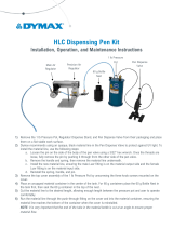
1.6 TRANSMITTER PRINCIPLES OF OPERATION
The mechanical system (filled assembly) consists of a lower diaphragm, a filled capillary tube, and an
upper diaphragm with a strain gage. The filled assembly transmits pressure from the process to the
strain gage diaphragm where it is converted to an electrical signal. The filled assembly isolates the
electronics from the high process temperatures.
The lower diaphragm is the surface in contact with the media being measured. This diaphragm can be
made from a choice of materials. The standard material is heat-treated 15-5 stainless steel with
DymaxTM coating. This has average corrosion and abrasion resistance and is similar to 17-4 stainless
steel. Other materials are also available including Hastelloy C-276 which has excellent corrosion resistant
properties (but is not good for abrasion). For other materials please consult the factory.
Behind the lower diaphragm is a capillary tube filled with a liquid (typically Hg, mercury) to the upper
diaphragm. As the process pressure deflects the lower diaphragm, the fill is displaced through the
capillary tube to deflect the upper diaphragm. Other fill liquids are available, please consult the factory.
The upper diaphragm has a strain gage element in the configuration of a Wheatstone Bridge. The
deflection of the upper diaphragm causes a change in the resistance of the strain gage and hence a
change in the balance of the bridge. The amount of imbalance is directly proportional to the applied
pressure. This completes the translation of pressure applied to the lower diaphragm into a usable
electrical signal.
Figure 1-1 Functioning Principle of the SPX 3xxx Filled Assembly

P/N: 974149 | Rev: 120519 | ECO: 50880
www.dynisco.com
From lab to production,
providing a window into the process
-10-
The low level output signal from the bridge is amplified via an instrumentation amp circuit. The
amplified signal then goes to the input of the analog-to-digital (A/D) converter.
Once the microprocessor has the converted voltage input from the A/D converter, the digital signal is
sent to a digital-to-analog (D/A) converter which modulates the current of the unit’s power supply
between 4 and 20 mA for an output current proportional to the applied pressure.
There is also a resistance temperature detector (RTD) in the tip of the sensor (SPX 3XXX Models only).
This sensor is used to measure the temperature of the snout tip to improve accuracy by compensating
for snout temperature effects on the pressure measurement. The temperature sensed by this RTD can
be accessed digitally via HART or via an optional 4-20 mA temperature output. 4 mA and 20 mA
correspond to 0 and 400 Celsius, respectively.
An alternative 3 wire RTD temperature output option is available. The 3 wire RTD temperature output
comes from a second RTD located in the snout tip (SPX 3XXX Models only, not available with 4-20 mA
temperature output). The RTD is a 100 ohm RTD with an alpha of 0.00385 ohms/°C.
1.7 CORRECT USE
When using an SPX as a safety component in accordance with the EC Machine Directive, Annex LLC, the
equipment manufacturer must take any necessary precautions to ensure that malfunction of the PT
cannot cause damage or injury.
For installation in explosive gas atmospheres the device must be installed in accordance with European
installation guidelines EN 60079-14. For category 1 (zone 0) installations, over voltage protection of the
electrical connections shall be in accordance to EN 60079-14.
When planning machinery and using one of the units from the SPX Family, follow the safety and accident
prevention regulations that apply to your application, such as:
• EN 60204, Electrical equipment in machines
• EN 12100, Machine safety, general design guidelines
• DIN 57 100 Part 410, Protection against electric shock
• EN 60079-0 Explosive atmospheres - General Requirements
• EN 60079-11 Explosive atmospheres - Intrinsically Safe Apparatus
• EN 60079-26 Special Requirements for EPL Ga
1.8 USER’S OBLIGATIONS
The operator or owner of the larger overall system, e.g. a machine, is responsible for following the
safety and accident prevention regulations that apply to the specific application.

P/N: 974149 | Rev: 120519 | ECO: 50880
www.dynisco.com
From lab to production,
providing a window into the process
-11-
2 NOTES ON SAFETY
2.1 GENERAL DANGER TO LIFE OR LIMB
The operator or owner of the larger overall system is responsible for following the safety and accident
prevention regulations that apply to the specific application.
DYNISCO will not be held liable for any injury, loss or damage resulting from failure to follow the
instructions in this manual.
The SPX is an ESD sensitive component. Electrostatic discharge may damage the SPX. Take ESD
precautions.
Electrical shock can result in death or serious injury. Avoid contact with the leads and terminals. High
voltage that may be present on leads can cause electrical shock.
Mounting and electrical connection of the PT must be done by specialists with EMC training, following
all applicable regulations, and in pressure-less, voltage-free, intrinsically safe condition with the
machine switched off. The machine must be secured against being switched back on!
Deviation of the supply voltage from the value given in the technical specifications, or reverse polarity,
can damage the pressure transmitter and cause malfunctions that can pose a risk of explosion.
Several configurations of the SPX are designed and approved for use in hazardous classified areas. Units
intended for installation in these areas must bear the applicable approval agency label.
The SPX can be used in media temperatures up to +400°C (based on configuration). If the pressure
transmitter is used in other applications, the safety and accident prevention regulations specific to that
application must be followed. Ambient temperature for the electronics housing is +85°C maximum in
areas that are not classified as hazardous.

P/N: 974149 | Rev: 120519 | ECO: 50880
www.dynisco.com
From lab to production,
providing a window into the process
-12-
Higher temperatures can result in damage and malfunction. Do not install the pressure transmitter in
places where these temperatures are exceeded.
Before connecting a HART handheld communicator in an explosive atmosphere, make sure the
instruments in the loop are installed in accordance with intrinsically safe or non-incendive field wiring
practices.
2.2 SPECIFIC DANGER TO LIFE OR LIMB
Toxic Hazard!
The SPX typically contains a very small amount of mercury, Hg (approx. 0.00322 in³ for a 6/18
configuration), as its transmission medium. If the diaphragm is damaged, mercury may escape. Never
transport or store the SPX without the protective cap. Remove the cap shortly before installation.
If mercury is inhaled or swallowed, seek medical attention immediately!
Mercury is hazardous waste and must be disposed of in accordance with applicable laws. DYNISCO will
accept defective PT’s. If mercury escapes, use airtight packaging!
2.3 CE EMC SPECIFIC REQUIREMENTS
Connect the shield of the connecting cable on both sides, making sure it conducts with full and
continuous contact.
When introducing the connecting cable into an EMC compliant switch cabinet, for example, connect the
shield correctly (cable gland, conducting, full contact, and continuous) to the conductive housing or
route it via a built-in cable connector that is also connected to the conductive housing. Connect unused
cable cores or free cable ends correctly to the cable shield on both sides.

P/N: 974149 | Rev: 120519 | ECO: 50880
www.dynisco.com
From lab to production,
providing a window into the process
-13-
2.4 ATEX INTRINSIC SAFETY APPROVAL SPECIFIC REQUIREMENTS
The housing of the SPX shall be connected reliably to the local equipotential bonding system. The
housing is electrically bonded to the process equipment through the process connection.
The installation of the SPX must be in accordance with European installation guidelines EN 60079-10.
For category 1 (zone 0) installations, over voltage protection of the electrical connections shall be in
accordance to EN 60079-14.
For category 1 (Zone 0) installations, care must be taken to avoid the danger of ignition due to
electrostatic discharges (ESD). The chance for static build up on the cable surface during normal
conditions of use, maintenance and cleaning must be eliminated. Install the cable in an appropriate
conduit or use some other cable reliable installation technique to avoid static electricity at the cable
surface.
The free length of the cable must be below 5 cm. If metallic conduits are used they need to be
grounded. If nonmetallic conduits are used they need to be antistatic (< 1G Ohm/cm2).
For application as category-1-equipment the connecting cable shall be equipped with a suitable
conductive coating (Rsurface < 109 ohms) to avoid possible electrostatic charge.
Those variants of the SPX that include the material aluminum shall be installed in such a way that
sparking as a result of impact or friction between aluminum and steel is excluded. Impact or friction
between aluminum and stainless steel is allowed if the existence of rust particles can be excluded.
After installation before operating the device the user must check that the complete installation and
wiring is intrinsically safe. Special care must be taken to insure that the power source is a certified
apparatus.
If the transmitter is installed in hazardous areas, only passive devices like switches or resistors may be
connected between the RCAL+ and RCAL- signals. Connection of any active electronic circuits or voltage
or current sources is not allowed.
In non-conduit units with the secondary 4-20mA option proper creepage and clearance distances must
be maintained between the mating connector and cabling per EN/IEC 60079-11. Proper creepage and
clearance distances are maintained using Dynisco SPX-T ATEX Intrinsically Safe mating connector cable
assemblies;
PT style connector cable assy’ s - 50 ft cable - p/n 641002, 100 ft cable - 641004
PC style connector cable assay’s - 50 ft cable - p/n 641012, 100 ft cable - 641014
Additional ATEX Intrinsically Safe approval specific requirements are provided on the EC Type
Examination certificate, Dynisco drawing number 975161, located in section 10 of this manual. The
medium temperature (Tmed) listed in the EC Type Examination certificate is defined as the temperature

P/N: 974149 | Rev: 120519 | ECO: 50880
www.dynisco.com
From lab to production,
providing a window into the process
-14-
of the pressure transmission fluid below the measuring diaphragm (See Figure 1-1). This temperature
can be verified by measuring the surface temperature at the base of the electronics housing.
Maximum allowed pressure range of each SPX by pressure range model code:
Pressure Range
XX
Code PSI Bar K
g
f/cm2 MPa KPa
01 1 0.07 0.07 0.007 7
02 2 0.14 0.14 0.014 14
03 3 0.2 0.2 0.02 20
04 4 0.27 0.27 0.027 27
05 5 0.35 0.35 0.035 35
06 10 0.7 0.7 0.07 70
07 15 1 1 0.1 100
08 25 1.75 1.75 0.175 175
09 50 3.5 3.5 0.35 350
10 75 5 5 0.5 500
11 100 7 7 0.7 700
12 150 10 10 1 1000
13 250 17.5 17.5 1.75 1750
14 500 35 35 3.5 3500
15 750 50 50 5 5000
16 1000 70 70 7 7000
17 1500 100 100 10 10000
18 2000 140 140 14 14000
19 2500 175 175 17.5 17500
20 3000 200 200 20 20000
21 5000 350 350 35 35000
22 7500 500 500 50 50000
23 10000 700 700 70 70000
24 15000 1000 1000 100 100000
25 20000 1400 1400 140 140000
26 25000 1750 1750 175 175000
27 30000 2000 2000 200 200000
33 200 14 14 1.4 1400

P/N: 974149 | Rev: 120519 | ECO: 50880
www.dynisco.com
From lab to production,
providing a window into the process
-15-
2.5 FM EXPLOSIONPROOF APPROVAL SPECIFIC REQUIREMENTS
Installation shall comply with the relevant requirements of the National Electrical Code (ANSI/NFPA 70)
Installation shall comply with the latest edition of the instruction manual. The latest edition of the
instruction manual is available for download from the Dynisco website:
www.dynisco.com
Replacement with non-factory components may adversely affect the safe use of the systems.
Additional SPX-T FM Explosionproof Approval specific installation requirements are provided on the
SPX-T FM Explosionproof Control drawing, Dynisco drawing number 000610, located in section 5 of
this manual.
Also see section 10 of this manual (Approvals and Certificates) for FM certificates of compliances that
list hazardous location limitations and approved model code configurations.
For SPX units that are explosion-proof approved the power supply rating is 13-30 Vdc.
1) Do not remove the transmitter push-button seal screws in explosive environments when the circuit is
live (applicable to all models except SPX-T).
2) Transmitter push-button seal screws must be fully engaged to meet Explosion-proof requirements
(applicable to all models except SPX-T).

P/N: 974149 | Rev: 120519 | ECO: 50880
www.dynisco.com
From lab to production,
providing a window into the process
-16-
2.6 CSA EXPLOSIONPROOF APPROVAL SPECIFIC REQUIREMENTS
SPX-T CSA Explosionproof Approval specific installation requirements are provided on the SPX-T CSA
Explosionproof Control drawing, Dynisco drawing number 000611, of this manual.
Contact factory for CSA certificates of compliances that list hazardous location limitations and approved
model code configurations.
SPX-T units are Explosionproof with Intrinsically Safe Output, Exia
Maximum non-hazardous voltage not to exceed 250V.
For SPX units the power supply rating is 13-30 Vdc.
1) Do not remove the transmitter push-button seal screws in explosive environments when the circuit is
live (applicable to all models except SPX-T).
2) Transmitter push-button seal screws must be fully engaged to meet Explosion-proof requirements
(applicable to all models except SPX-T).
See pressure range table in section 2.4 for maximum allowed pressure range of each SPX by
pressure range model code:

P/N: 974149 | Rev: 120519 | ECO: 50880
www.dynisco.com
From lab to production,
providing a window into the process
-17-
2.7 NEPSI INTRINSIC SAFETY REQUIREMENTS
一、 产品安全使用特殊条件
产品防爆合格证号后缀“X”代表产品安全使用有特殊条件:
1. 产品外壳含有轻金属,用于 0区时需注意防止由于冲击或摩擦产生的点燃危险。
2. 产品外壳含非金属,使用时须防止产生静电火花,只能用湿布清理。
二、产品使用注意事项
1. 产品温度组别与使用环境温度范围和介质温度范围之间关系为:
温度组别 T6 T4
使用环境温度范围 -20℃~+50℃ -20℃~+85℃
介质温度范围 -20℃~+60℃ -20℃~+85℃
2. 本安电气参数:
最高输入电压
Ui (V)
最大输入电流
Ii (mA)
最大输入功率
Pi (W)
最大内部等效参数
Ci(nF) Li(µH)
30 100 0.75 4.5 40
3. 该产品必须与已通过防爆认证的关联设备配套共同组成本安防爆系统方可使用于爆炸性
气体环境。其系统接线必须同时遵守本产品和所配关联设备的使用说明书要求,接线端子不得接
错。
4. 用户不得自行更换该产品的零部件,应会同产品制造商共同解决运行中出现的故障,以
杜绝损坏现象的发生。
5. 产品的安装、使用和维护应同时遵守产品使用说明书、GB3836.13-2013“爆炸性环境 第
13部分:设备的修理、检修、修复和改造”、GB3836.15-2017“爆炸性环境第15部分:电气装置的
设计、选型和安装”、GB3836.16-2017“爆炸性环境第16部分:电气装置的检查和维护”、GB50257-
2014 “电气装置安装工程爆炸和火灾危险环境电力装置施工及验收规范”的有关规定。

P/N: 974149 | Rev: 120519 | ECO: 50880
www.dynisco.com
From lab to production,
providing a window into the process
-18-
2.8 NEPSI EXPLOSIONPROOF SPECIFIC REQUIREMENTS
二、 产品安全使用特殊条件
产品防爆合格证号后缀“X”代表产品安全使用有特殊条件:
1. 产品外壳含非金属,使用时须防止产生静电火花,只能用湿布清理。
2. 涉及隔爆结合面的维修须联系产品制造商。
二、产品使用注意事项
1. 产品温度组别与使用环境温度范围和介质温度范围之间关系为:
温度组别 使用环境温度
T6 -20℃~+60℃
T5 -20℃~+85℃
2. 用户在使用时应将产品外壳可靠接地。
3. 安装现场应不存在对产品外壳有腐蚀作用的有害气体。
4. 用户不得自行更换该产品的零部件,应会同产品制造商共同解决运行中出现的故障,以
杜绝损坏现象的发生。
5. 产品的安装、使用和维护应同时遵守产品使用说明书、GB3836.13-2013“爆炸性环境 第
13部分:设备的修理、检修、修复和改造”、GB3836.15-2017“爆炸性环境第15部分:电气装置的
设计、选型和安装”、GB3836.16-2017“爆炸性环境第16部分:电气装置的检查和维护”和
GB50257-2014“电气装置安装工程爆炸和火灾危险环境电力装置施工及验收规范”的有关规定。

P/N: 974149 | Rev: 120519 | ECO: 50880
www.dynisco.com
From lab to production,
providing a window into the process
-19-
2.9 SAFETY INTEGRITY AND PERFORMANCE LEVEL APPLICATIONS
User’s obligations
The operator or owner of the larger overall system, e.g. a machine, is responsible for following the
safety and accident prevention regulations that apply to the specific application.
Intended Use
See Certificate in section 10.5
Safety Function
See Certificate in section 10.5
For units with the optional monitoring channel (Guardian Series, Option Code = GCxxx):
Under normal operating conditions the relay contacts are closed. In the event that a failure is detected
the relay contacts open. Detectable failures include:
1) Loss of Power
2) Open Gage
3) Input over a predefined (customer selectable at time of order) threshold
The Guardian Series transducer has been designed to provide a protective measure. This has been done
by the avoidance and control of systematic and random failures.
This product will:
Measure the pressure and provide a safety relay output. Since this is being used to perform a protective
measure, this sensor should only be used for monitoring the pressure and not controlling the process.
Best practices declare that safety and control must be independent from each other.
The Guardian Series transducer detects many hardware failures including an open or short in the
measuring gage and if there is an overpressure condition. If any of these failures occur, the output relay
will open. It is the user’s responsibility to connect this relay to the system in such a way that when this
relay opens, it brings the system to a safe state.
This fault state is not latched. It is up to the user to latch this error if desired.
Recommended practices

P/N: 974149 | Rev: 120519 | ECO: 50880
www.dynisco.com
From lab to production,
providing a window into the process
-20-
This Guardian Series transducer must be installed in such a way that the opening of the output relay will
bring the system to a safe state. In this safe state the instrument that is monitoring the pressure should
be left operational.
This error indication is not latched. If it is necessary to latch the error until it is manually reset, this is the
user’s responsibility.
At startup and on a periodic basis the safety system should be tested to ensure proper operation. This
will require applying a pressure to the Guardian Series transducer that is over the safe level but less than
the maximum pressure. Verify that the protective measure is initiated to take the machine to a safe
operating condition.
Use of qualified personnel
The product may only be assembled, installed, configured, commissioned, operated and maintained by
persons with proven skills. Persons with proven skills are suitably experienced to operate devices,
systems, plant and machinery in accordance with the general standards and guidelines for safety
technology.
It is the user’s responsibility only to employ personnel who:
• Are familiar with the basic regulations concerning health and safety and accident prevention
• Have read and understood the safety guidelines given in this description
• Have a good knowledge of the generic and specialist standards applicable to the specific
application
Connecting Safety Relay
Relay specs: Maximum switching voltage: 200Vdc; Maximum switching current: 0.5A
Device pinout
/