Page is loading ...

INSTALLATION INSTRUCTIONS
Model # P1620,P1621
READ AND SAVE THESE INSTRUCTIONS
WA R N I N G ! S H U T P O W E R O F F AT F U S E O R C I R C U I T B R E A K E R .
AVERTISSEMENT! COUPER LE COURANT AU NIVEAU DES FUSIBLES OU DU DISJONCTEUR.
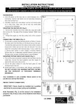
PREPARING FOR INSTALLATION (Fig.
1
)
1. Shut off the power at the fuse box or circuit breaker box and
remove the old fixture, including the mounting hardware.
2. Carefully unpack your new fixture and lay out all the parts in a
clear area. Take care not to misplace any small parts
necessary for installation.
3. Remove screws (L) and rubber rings (K) to separate metal
shade (M) from back plate (G).
4. Remove ball nuts (J) and rubber washers (H) to separate back
plate (G) from crossbar (A).
5. Attach crossbar (A) to outlet box (C) (not included) using outlet
box screws (B). The side of crossbar (A) marked “GND” must
face out.
CONNECTING THE WIRES (Fig. 2)
6. Connect the electrical wires as shown in Fig.2. Make sure that
all wire connectors are secured. If your outlet box (C) has a
ground wire (green or bare copper), connect the fixture’s
ground wire to it. Otherwise, connect the fixture’s ground wire
directly to the crossbar (A) using the green screw (E) provided.
COMPLETING THE INSTALLATION (Fig. 1)
7. Align back plate (G) onto screws (D) and secure with ball nuts
(J) and rubber washers (H). (Fig.1)
8. Place metal shade (M) over back plate (G) and secure with
screw (L) and rubber rings (K).
9. To prevent moisture from entering outlet box (C) and causing a
short, use clear silicone sealant (i.e. Indoor/Outdoor Silicone
Sealant) to outline the outside of metal shade (M) where it
meets the wall leaving a space at bottom to allow moisture a
means to escape. (Fig.3)
Your installation is now complete. Return power to the outlet box
and test the fixture.
Replacing LED module (Fig.4)
The LED module can be replaced by a qualified electrician without
cutting of wire and without damage to any decorative element to
which the fixture is attached. See installation steps for more
details (Fig 4.)
a. Shut off the power.
b. Remove fixture from the wall by loosening screws (L) and rubber
rings (K) and ball nuts (J) and rubber washers (H), then disconnect
the wires. (Fig. 1)
c. Remove screws (S) and LED shade (R) from support frame (N).
d. Remove screws (Q) and LED module (P) from support frame
(N),then carefully pull the wire out of the hole.
e. Reverse steps b-d for installing the new LED module.
Note: Illustration (Fig. 1) on this manual is for installation
purposes only. It may or may not be identical to the fixture
purchased.
Dimmable with ELV and/or LED compatible wall dimmer switches.
Fig. 1
BARE COPPER(GROUND)
Fig.2
FIXTURE
WIRES
WHITE
BLACK
(HOT)
WIRES
HOUSE
GREEN O R
WHITE
(NEUTRAL)
WIRES
HOUSE
(GROUND)
COPPE R
BARE
FIXTURE
WIRES
BLACK
WIRES
FIXTURE
GREEN OR
HOUSE
WIRES
Fig. 3
Caulking
Backplate
“CAUTION-RISK OF FIRE CONSULT A QUALIFIED ELECTRICIAN
TO ENSURE CORRECT BRANCH CIRCUIT CONDUCTOR”
ATTENTION – RISQUE D’INCENDIE, CONSULTER UN ÉLECTRICIEN
QUALIFIÉ POUR VOUS ASSURER QUE LES CONDUCTEURS DE LA
DÉRIVATION SONT ADÉ
QUATS.
Fig. 4
Crossbar (1)
Ground Screw (1)
O
utlet box
Screws
(2)
/