Installation Instructions
GENERAL
These installation instructions are for the wall mounting of
the TEMP system thermostat 33CSTM(T)-01, the VVTt
system monitor thermostat 33CSVM(T)-32, the VVT sys-
tem zone controller 33CSZC--01, the VVT system bypass
controller 33CSBC--00, and the Linkage Thermostat
33CSKITLST-08. See Fig. 1 and 2.
Book 1 4
Tab 11a 13a PC 111 Catalog No. 533-339 Printed in U.S.A. Form 33CS-25SI Pg 1 4-98 Replaces: 33CS-1SI
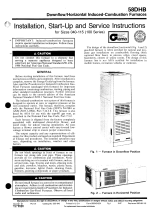
Fig. 1 — Monitor Thermostat or TEMP System Thermostat with Timeclock,
or Linkage Thermostat
Fig. 2 — Monitor Thermostat or TEMP System Thermostat Without Timeclock,
Zone Controller, or Bypass Controller
33CS
TEMP System Thermostat, Monitor Thermostat
Zone Controller, Bypass Controller, Linkage Thermostat
Manufacturer reserves the right to discontinue, or change at any time, specifications or designs without notice and without incurring obligations.

INSTALLATION
Thermostat Placement — Begin the thermostat/
controller installation by determining where the device will
be located. In most cases, this will be pre-determined by the
building plans.
The thermostat/controller should be located on an interior
wall, about 5 ft from the ground. The device should be lo-
cated away from direct sunlight, drafts, or interior heat sources
which may influence temperature readings.
The device may also be mounted in a remote location with
the use of an optional remote room sensor.
To mount the thermostat, perform the following:
1. Cut a hole in the wall for the terminal board housing. The
hole should be 1
3
⁄
4
in. by 1
3
⁄
4
inches. See Fig. 3.
NOTE: A 2-in. by 4-in. electric box mounted horizon-
tally may be used instead of cutting the hole.
2. Remove the cover from the thermostat/controller. Care-
fully remove the circuit board from the backplate of the
thermostat/controller. Line up the backplate with the hole
in the wall. Push the protruding part of the backplate into
the hole. Pull the thermostat/controller wires out through
the backplate.
3. Attach backplate to wall with screws provided.
Wiring Requirements — The wiring requirements for
the Comfort System are:
THERMOSTAT TO THERMOSTAT — Use 20 gage,
3-conductor, shielded, stranded wire, color coded (RED,
BLACK, GREEN), plenum rated if required, long enough to
run from thermostat to thermostat in daisy-chain configu-
ration, with a maximum length of 1000 ft.
THERMOSTAT TO DAMPER ACTUATOR OR RELAY
PACK — Use 18 gage, 5-conductor, shielded, stranded wire,
color coded (RED, WHITE, BLUE,YELLOW, GREEN), ple-
num rated if required, long enough to run from thermostat to
damper actuator or relay pack.
RELAYPACK TO HVAC UNIT — Use six-, seven-, or eight-
conductor wire, depending on HVAC unit. Sized to run from
relay pack to the wiring terminals of the HVAC unit.
NOTE: Do not run the thermostat network and the control
wire in the same conduit for more than 5 ft. Never run wires
near any cable carrying AC voltage. For further wiring in-
formation, consult the local Carrier distributor.
Power required to each damper actuator or relay pack is
24 vac/ 10 va. Typical wiring is 18 gage thermostat wire (stand-
ard or plenum cable). The maximum load of a relay contact
is 24 vac, 1 amp. A short in the field wiring will cause non-
warranty damage to the relay board. Test before attaching to
relay pack or damper actuator.
Call the local Carrier representative if more information
is needed about wiring.
POWER SUPPLY TO THERMOSTAT — Use 18-gage,
2-conductor thermostat wire to connect the power supply board
to the linkage thermostat. If the power supply board is over
100 ft from the thermostat, relocate the power supply board
and the equipment transformer to within 100 ft of the
thermostat.
Wiring Connections
Electric shock can cause injury or death. Ensure power
to the HVAC unit has been disconnected before wiring.
To wire the thermostat/controller, perform the following:
1. Connect the communication bus and power wiring to the
wiring connection block of the thermostat. See Fig. 4
or 5.
2. Push the wires back into the wall.
3. Align the terminal board with the right track in the back
plate housing. See Fig. 6. The ribbon strip side of the ter-
minal block should be away from the wall. Push the ter-
minal block into the track until about
1
⁄
2
-in. is left
protruding.
4. Align the ribbon cable from the thermostat/controller cir-
cuit board with the ribbon connector on the terminal board
and push gently to connect.
5. Push the terminal board fully into backplate until the latch
clicks into place.
6. Place the foam backing on the circuit board. Slide the
circuit board under the back plate securing bars. DO NOT
CREASE RIBBON CABLE.
7. Align thermostat board with alignment pin. Gently pull
down on the thermostat latch and press firmly until the
circuit board snaps into place.
8. If optional locking thermostat cover is purchased, insert
locking clip on the inside of the thermostat cover. Push
firmly into place.
9. Insert tabs on thermostat cover into top slots on the back-
plate. Press firmly on the bottom of the thermostat cover
to snap cover into place.
NOTE: If the optional locking thermostat cover was in-
stalled, the key must be inserted into the locking device
to remove front cover.
Fig. 3 — Mounting Hole Dimensions
2


Fig.5—Wiring Connections (Linkage Thermostat)
Fig.6—Terminal Board Installation
Copyright 1998 Carrier Corporation
Manufacturer reserves the right to discontinue, or change at any time, specifications or designs without notice and without incurring obligations.
Book 1 4
Tab 11a 13a PC 111 Catalog No. 533-339 Printed in U.S.A. Form 33CS-25SI Pg 4 4-98 Replaces: 33CS-1SI
/