Page is loading ...

EN
www.bdsensors.cz
BA_DS4XX_EX_E
Operating manual
Electronic Pressure Switch AX14-DS4XX for IS-areas
AX14-DS400, AX14-DS400P, AX14-DS401, AX14-DS401P
Headquarters
BD SENSORS s.r.o.
Hradišťská 817
CZ - 687 08 Buchlovice
Czech Republic
Tel.: +42 (0) 572-4110 11
Fax: +42 (0) 572-4114 97
Eastern Europe
BD SENSORS GmbH
BD-Sensors-Str. 1
D - 95199 Thierstein
Germany
Tel.: +49 (0) 9235-9811-0
Fax: +49 (0) 9235-9811-11
Russia
BD SENSORS RUS
39a, Varshavskoe shosse
RU - Moscow 117105
Russia
Tel.: +7 (0) 95-380 1683
Fax: +7 (0) 95-380 1681
China
BD SENSORS China Co, Ltd.
Room B, 2nd Floor, Building 10,
No. 1188 Lianhang Rd.
201112 Shanghai,
China
Tel.: +86 (0) 21-51600 190
Fax: +86 (0) 21-33600 613
further agencies in:
EUROPE
Belgium
Denmark
Finland
France
Great Britain
Greece
Italy
Lithuania
Luxemburg
Netherlands
Norway
Poland
Portugal
Romania
Sweden
Switzerland
Slovakia
Spain
Turkey
UK
Ukraine
AFRICA
Egypt
South Africa
ASIA
India
Iran
Israel
Japan
Kazakhstan
Malaysia
Singapore
Taiwan
Thailand
Vietnam
AUSTRALIA
The addresses of our distribution partners are listed on our
homepage www.bdsensors.com. It is possible to download
data sheets, operating manuals, ordering codes and certifi-
cates, as well.
Table of contents
1. General information
2. Product identification
3. Mechanical installation
4. Special regulations for IS-Areas
5. Electrical Installation
6. Initial start-up
7. Operation
9. Maintenance
11. Disposal
12. Warranty conditions
13. Declaration of conformity / CE
1. General information
1.1 Information on the operating manual
This operating manual contains important information on
proper usage of the device. Read this operating manual
carefully before installing and starting up the pressure
measuring device.
Adhere to the safety notes and operating instructions which
are given in the operating manual. Additionally applicable
regulations regarding occupational safety, accident preven-
tion as well as national installation standards and engineering
rules must be complied with!
For the installation, maintenance and cleaning of the device,
you must absolutely observe the relevant regulations and
stipulations on explosion protection (VDE 0160, VDE 0165 or
EN 60079-14) as well as the occupational safety provisions.
The device was constructed acc. to standards
EN IEC 60079-0:2018, EN60079-11:2012,, EN 60079-
26:2015.
This operating manual is part of the device, must be kept
nearest its location, always accessible to all employees.
This operating manual is copyrighted. The contents of this
operating manual reflect the version available at the time of
printing. It has been issued to our best knowledge. However,
errors may have occurred. BD SENSORS is not liable for any
incorrect statements and their effects.
– Technical modifications reserved –
1.2 Symbols used
DANGER! – dangerous situation, which may result in
death or serious injuries
WARNING! – potentially dangerous situation, which may
result in death or serious injuries
CAUTION! – potentially dangerous situation, which may
result in minor injuries
! CAUTION! – potentially dangerous situation, which may
result in physical damage
NOTE – tips and information to ensure a failure-free
operation
1.3 Target group
WARNING! To avoid operator hazards and damages of
the device, the following instructions have to be worked
out by qualified technical personnel.
1.4 Limitation of liability
Failure to observe the instructions or technical regulations, im-
proper use and use not as intended, and alteration of or da-
mage to the device will result in the forfeiture of warranty and
liability claims.
1.5 Intended use
- The electronic pressure switch DS 4XX has been
developed, according to the type for applications in abso-
lute, vacuum and overpressure measurement. It is
equipped with a 4-digit LED-display to show the current
system pressure. Depending on the device and the me-
chanical connection it is suitable for various areas of use.
- - The device is intended for converting the physical pa-
rameter of pressure into an electric signal. The current
system pressure is shown in a 4-digit LED-display.
- The device has to be used only for this purpose, consid-
ering the following information.
- Devices with 3-A and / or EHEDG certified process con-
nection have been developed especially for applications
in food and pharmaceutical industry. The process con-
nection is hygienic and can be sterilized.
- Permissible measuring and cleaning media are gases or
liquids, which are compatible with the media wetted parts
of the device (according to data sheet) and your system.
This must be ensured for the application.
- This operating manual applies to devices with explosion
protection approval and is intended for the use in
IS-areas. A device has an explosion protection approval
if this has been specified in the purchase order and
confirmed in our order confirmation. In addition, the
manufacturing label contains the -symbol.
- It is the operator's responsibility to check and verify the
suitability of the device for the intended application. If any
doubts remain, please contact our sales department in
order to ensure proper usage. BD SENSORS is not liable
for any incorrect selections and their effects!
- Permissible media are gases or liquids, which are com-
patible with the media wetted parts described in the data
sheet. In addition it has to be ensured, that this medium
is compatible with the media wetted parts.
- The technical data listed in the current data sheet are
engaging. If the data sheet is not available, please order
or download it from our homepage.
(http://www.bdsensors.com)
WARNING! Danger through improper usage!
Only use the device in permissible media and in accor-
dance with its intended use.
- Do not use the device as a ladder or climbing aid.
- The device must not be altered or modified in any way.
- BD SENSORS is not liable for damage caused by im-
proper or incorrect use.
NOTE - Excessive dust accumulation and complete
coverage with dust must be prevented!
1.6 Safety technical maximum values
AX 4 - DS 4XX:
Permissible temperatures for environment:
-20 ... 60 °C with patm 0.8 bar up to 1.1 bar
Ui = 28 V, Ii = 93 mA, Pi = 660 mW, Ci ≈ 0 nF, Li ≈ 0 µH
plus cable inductivities 1 µH/m and cable capacities
100 pF/m (for cable by factory)
1.6.1. Special conditions for safe use
- No energy may be supply from the outside into the active
switching exits.
- The equipment designed with connector have to be in-
stalled in such a way that the Degree of protection IP20 al-
ways will be kept.
- The safety and assembly notes contained in the operating
instructions and the ambient temperature range -25 °C to
+70 °C have to be observed.
1.7 Package contents
Please verify that all listed parts are undamaged included in
the delivery and check for consistency specified in your order:
- electronic pressure switch, series DS 4XX
- for mechanical pressure ports DIN 3852: o-ring
(pre-assembled)
- this operating manual
1.8 UL-approval (for devices with UL marking)
The UL – Approval was done with respect to U.S. standards
norms which also correspond with the applicable Canadian
standard norms for safety.
Observe the following points so that the device meets the
requirements of the UL approval:
- only indoor usage
- maximum operating voltage: according to data sheet
- The device must be operated via a supply with energy li-
mita-tion (acc. to UL 61010) or an NEC Class 2 energy
supply.
2. Product identification
The device can be identified by its manufacturing label. It
provides the most important data. By the ordering code the
product can be clearly identified. The programme version of
the firmware, (e. g. P07) will appear for about 1 second in the
display after starting up the device. Please hold it ready for
inquiry calls.
Fig. 1 manufacturing label- example
! The manufacturing label must not be removed from the
device!
3. Mechanical installation
3.1 Mounting and safety instructions
WARNING! Install the device only when depressurized
and currentless!
WARNING! This device may only be installed by qualified
technical personnel who has read and understood the
operating manual!
DANGER! Caused by the explosion hazard following
instructions have to be complied with:
- The technical data listed in the EC type-examination
certificate are engaging. If the certificate is not
available, please order or download it from our
homepage: http://www.bdsensors.com
- Working on supplied (active) parts, except for intrin-
sically safe circuits, is principally prohibited during
an explosion hazard.
- Make sure that an equipotential bonding is in place
for the entire course of the line, both inside and
outside the intrinsic area.
- In case of increased danger of lightning strike or
damage by overvoltage, a stronger lightning protec-
tion should be planned.
- Observe the limiting values specified in the EC type-
examination certificate. (Capacitance and induct-
ance of the connection cable are not included in the
values.)
- Make sure that the entire interconnection of intrinsi-
cally safe components remains intrinsically safe.
The operator is responsible for the intrinsic safety
of the overall system (installation of intrinsic parts).
- Do not mount the device in a pneumatic flow rate!
- Excessive dust deposits (over 5 mm) and a com-
plete dust covering must be avoided!
- The external circuit must prevent an external power-
inflow to the contacts. Suitable signal separating
devices which fulfil this demand have to be used.
! Handle this high-sensitive electronic precision measuring
device with care, both in packed and unpacked condition!
! There are no modifications/changes to be made on the
device.
! Do not throw the package/device!
! To avoid damaging the diaphragm, remove packaging
and protective cap directly before starting assembly. The
delivered protective cap has to be stored!
! The measuring point must be designed in such a way that
cavitation and pressure surges are avoided
! Place the protective cap on the pressure port again
immediately after disassembling.
! Handle the unprotected diaphragm very carefully - it is
very sensitive and may be easily damaged.
! Do not use any force when installing the device to pre-
vent damage of the device and the plant!
! The display and the plastic housing are equipped with
rotational limiters. Please do only rotate the display or the
housing within the limit.
! For installations outdoor and in damp areas following
these instructions:
- To prevent moisture admission in the plug the
device should be installed electrically after
mounting, at once. Otherwise a moisture admission
has to be blocked e.g. by using a suitable protection
cap. (The ingress protection in the data sheet is
valid for the connected device.)
- Choose an assembly position, which allows the
flow-off of splashed water and condensation. Avoid
permanent fluid at sealing surfaces!
- When using a cable gland device, turn the outgoing
cable downwards. If the cable has to be turned
upwards, then point it downward so the moisture
can drain.
- Install the device in such a way that it is protected
from direct solar irradiation. Direct solar irradiation
can lead to the permissible operating temperature
being overstepped in the worst case. This is
prohibited for applications in IS-areas!
! For devices with gauge reference in the housing (small
hole next to the electrical connection), install the device
in such a way, that the gauge reference is protected from
dirt and moisture. Should the device be exposed to fluid
admission, the functionality will be blocked by the gauge
reference. An exact measurement in this condition is not
possible. Furthermore this can lead to damages on the
device.
! The permissible tightening torque depends on the con-
ditions on site (material and geometry of the mounting
point). The specified tightening torques for the pressure
switch must not be exceeded!
Take note that no inadmissibly high mechanical stresses
occur at the pressure port as a result of the installation,
since this may cause a shifting of the characteristic curve
or to the demage. This is especially important for very
small pressure ranges as well as for devices with a
pressure port made of plastic.
In hydraulic systems, position the device in such a way
that the pressure port points upward (ventilation).
Provide a cooling line when using the device in steam
piping.
If the device is installed with the pressure connection up,
it has to be made sure that no liquid drain off at the case.
Humidity and dirt can block the relative cover in the case
and it could lead to malfunctions through this. Dust and
dirt must be removed from the edge of the thread
connection of the electrical connection if required.
3.2 Conditions for devices with 3-A symbol and / or
EHEDG certificate
The device or its connecting piece must be installed in such
a way that the surfaces are self-draining (permissible insta-
llation position 273° … 87°).
! Make sure that the welding socket is mounted flush
inside the tank.
The user is responsible for:
the correct size of the seal and the choice of an
elastomeric sealing material that complies with
the 3-A and / or EHEDG standard(s)
- an easy to clean installation position of the pres-
sure switch with little dead space, as well as de-
finition / verifi-cation / validation of a suitable cle-
aning process
- defining adequate service intervals
3.3 Mounting and safety instruction oxygen
DANGER! Explosion hazard, with devices for oxygen
applications, when used improperly. To ensure a usage
without danger, the following points must be adhered to:
- Make sure, your device has been ordered and
delivered as a special version for oxygen applica-
tions. You can check the manufacturing label (see
figure 1). If the ordering code ends with "007", then
the device is suitable for oxygen applications.
- At time of delivery the device is packed into a plastic
bag in order to prevent it from impurity. Please
observe the indication label "Device for oxygen,
unpack only directly before assembling". Also, avoid
any skin contacts during unpacking and assembly,
in order to prevent greasy residues on the device.
- During installation, the respective explosion protec-
tion regulations have to be met.
- Note the entire design requirements meet the
standard demand of BAM (DIN 19247).
- Transmitters with o-rings of 70 EPDM 281:
permissible maximum values: 15 bar/ 60° C and
10 bar/ 60 up to 90°C.
- Transmitters with o-rings of FKM Vi 567:
permissible maximum values: 15 bar/ 60° C.
3.4 General installation steps
- Carefully remove the pressure measuring device from
the package and dispose of the package properly.
- Go ahead as detailed in the specific instructions below.
3.5 Installation steps for DIN 3852
DO NOT USE ANY ADDITIONAL SEALING
MATERIALS, LIKE YARN, HEMP OR TEFLON TAPE!
- Check to ensure the proper groove fitting of the o-ring
and additionally to ensure no damage to the o-ring.
- Ensure that the sealing surface of the taking part is
perfectly smooth and clean. (RZ 3.2)
- Screw the device into the corresponding thread by hand.
- If you have a device with a knurled ring, the transmitter
has to be screwed in by hand only.
- Devices with a spanner flat have to be fully tightened with
an open-end wrench (G1/4": approx. 5 Nm; G1/2":
approx. 10 Nm; G3/4": approx. 15 Nm; G1": approx. 20
Nm; G1 1/2": approx. 25 Nm).
- The indicated tightening torques must not be
exceeded!
3.6 Installation steps for EN 837
- Use a suitable seal, corresponding to the medium and
the pressure input (e. g. a cooper gasket).
- Ensure that the sealing surface of the taking part is
perfectly smooth and clean. (RZ 6.3)
- Screw the device into the corresponding thread by hand.
- Tighten it with a wrench (for G1/4": approx. 20 Nm; for
G1/2": approx. 50 Nm).
- The indicated tightening torques must not be
exceeded!
-
G1/4" EN
837
-
p ≤ 600
bar
Counterpart has to be of steel
according to DIN 17440 with
strength Rp0.2 ≥ 190 N/mm2
G1/2" EN
837
p ≤ 1000
bar
NOTE - Please refer to data sheet or contact sales depart-
ment at BD SENSORS regarding max. permitted pressure of
device.
3.7 Installation steps for NPT
- Use a suitable seal (e. g. a PTFE-strip).
- Screw the device into the corresponding thread by hand.
- Tighten it with a wrench (for 1/4" NPT: approx. 30 Nm; for
1/2" NPT: approx. 70 Nm).
- The indicated tightening torques must not be
exceeded!
3.8 Installation steps for dairy pipe
Note the chapter “3.2 Conditions for devices with
3-A symbol”
- Check to ensure that the O-ring fits properly into the
intended groove in the mounting part.
Chapter "3.2” has been noticed.
EHEDG conformity is only ensured in combination with an
approved seal. This is e.g.:
- ASEPTO-STAR k-flex upgrade seal by Kieselmann
GmbH
- Centre the dairy pipe connection in the counterpart.
- Screw the cup nut onto the mounting part.
- Then tighten it with a hook wrench.
3.9 Installation steps for Clamp and Varivent
- Use a suitable seal corresponding to the medium and the
pressure input.
- Put the seal onto the corresponding mounting part.
- Centre the Clamp or Varivent connection on the fitting
counterpart with seal.
EHEDG conformity is only ensured in combination with an
approved seal. This is e.g.:
for Clamp connections: T-ring seal from Combifit Internatio-
nal B.V.
- for Varivent connections: EPDM-O-ring which is FDA-
listed
- Then fit the device with a suitable fastening element
(e. g. semi-ring or retractable ring clamp) according to the
supplier’s instructions.
- Note, that P40 can only be used for tank flanges.
3.10 Mounting steps for G1″ cone connection
- 1 Screw the device into the mating thread by hand (seal
produced metallically)
- 2 Then tighten it using an open-end wrench. Permissible
tightening torques for pressure switch: pN < 10 bar: 30 Nm; pN
≥ 10 bar: 60 Nm
3.11 Conditions for devices, with EHEDG certificate
Install the device according to the requirements given in
EHEDG Guidelines 8, 10 and 37. That is to mount the device
in a self-draining orientation. The device should be installed
flush to the process area. If mounting in a T-piece, the ratio
between the depth of the upstand (L) and the diameter (D) of
the upstand shall be L/D<1. If welded adapters are used, the
food contact surface must be smooth, and the welding has to
be done according to EHEDG Guideline 9 and 35. Suitable
pipe couplings and process connections must be applied ac-
cording to the EHEDG Position Paper. (List the available
ones.)
3.12 Positioning of the display module
WARNING! It is prohibited to open the devices in the
presence of explosion hazards. Therefore it is recom-
mended to position the display and operating module
together with the mechanical installation.
! Pay attention that no moisture can enter the device.
Moreover, the seals and the sealing surfaces should not
get dirty, as this may cause a reduction of the degree of
protection depending on the case of application or place
of installation. This can lead to a breakdown of the
devices or to irreparable damages on the device.
The display and operating module is continuously rotatable so
that clear readability is guaranteed even in unusual installation
positions. To change the position go ahead as follows:
- Screw off the housing cap by hand.
- Turn the display and operating module carefully into the
desired position by hand. The module is equipped with a
rotational limiter.
- Before screwing on the cap again, the o-ring and sealing
surfaces of the housing have to be checked for damage
and if necessary have to be changed!
- Afterwards screw the housing cap on by hand and make
sure that the housing is firmly locked again.
! Pay attention that no moisture can enter the device.
Moreover, the seals and the sealing surfaces should not
get dirty, as this may cause a reduction of the degree of
protection depending on the case of application of place
of installation. This can be lead to a breakdown of the
devices or to irreparable damages on the device.
4. Special regulations for IS-Areas
4.1 Protection against electrostatic charge hazards
Different types of devices partially consist of chargeable plas-
tic components. A potential electrostatic charge presents the
danger of spark generation and ignition. An electrostatic
charge must therefore be absolutely prevented.
Generally, a shielded cable must be used.
Avoid friction on the plastic surfaces!
Do not clean the device dry! Use, for example, a damp
cloth.
4.2 Overvoltage protection
If the pressure switch is used as electrical equipment of
category 1 G or 2 G, a suitable overvoltage protection device
must be connected in series (attend the valid regulations for
operating safety as well as EN60079-14).
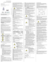
4.3 Schematic circuit design
The operation of an intrinsically safe device in intrinsic safe
areas requires special care when selecting the necessary
Zener barrier or transmitter repeater devices to be able to use
the device’s characteristics to the full extent. The following di-
agram shows a typical arrangement of power supply, Zener
barrier and pressure switch.
Fig. 2 Circuit diagram
4.4 Exemplary circuit description
The supply voltage of e. g. 24 VDC provided by the power
supply is led across the Zener barrier. The Zener barrier
contains series resistances and Zener diodes as protective
components. Subsequently, the operating voltage is applied
to the pressure switch and, depending on the pressure,
a particular signal current will flow.
intrinsic safe area
contact
pressure switch
Supply
24 VDC
contact
+ VS
- VS
+ VS
- VS
VS
DS 400
Ordering
code
Type
designation
Serial
number
Safety technical
max. values
Number of EC type-examination
certificate, Ex-designation

DS4XX_EX_E_SRO_09.08.2021
DANGER! When installing the intrinsically safe device as
a zone-0-equipment, the supplying must be carried out
by a power supply which must be galvanically insulated
and which is not allowed to be grounded.
4.5 Functional selection criteria for Zener barriers and
galvanic power supply
The minimum supply voltage V
S
min of the pressure switch must
not fall short since a correct function of the device can other-
wise not be guaranteed. The minimum supply voltage has
been defined in the respective product-specific data sheet
under "Output signal / supply".
When using a galvanically insulated amplifier with a linear
bonding, please attend that the terminal voltage of the device
will decrease like it does with a Zener barrier. Furthermore, it
has to be attended that the supply of the pressure switch will
also decrease with an optionally used signal amplifier.
4.6 Test criteria for the selection of the Zener barrier
In order not to fall below V
S
min it is important to verify which
minimum supply voltage is available at full level control of the
device.
The technical data of the barrier will usually provide you with
the information needed for the selection of the Zener barrier.
However, the value can also be calculated. If a minimum
supply of 16 V is assumed, then – according to Ohm’s law – a
particular voltage drop will result on the series resistance of
the Zener barrier. If, for a pressure switch with PNP contact,
the contact is also activated, the additional current flowing
from the contact to the load resistor will also flow through the
Zener barrier or the output of a transmitter repeater. The
higher the load current, the lower the available minimum
operating voltage. In the diagram shown, the maximum
current can be calculated from the voltage difference
(Va
b
Barrier
e
max) between input and output of the Zener barrier
divided by the series resistance of the Zener barrier. The
maximum signal current must be subtracted from this value. If
the available residual current is smaller than the current
required at the contact, either a different barrier or a higher
supply voltage before the barrier should be chosen.
When selecting the power supply, the maximum operat-
ing conditions according to the EC type-examination
certificate must be observed. When assessing the power
supply, please refer to their current data sheets to ensure
that the entire interconnection of intrinsically safe compo-
nents will remain intrinsically safe.
4.7 Calculation example for the selection of the Zener
barrier
The nominal voltage of the power supply in front of the Zener
barrier is 24 VDC 2%. This results in:
- greatest supply voltage:
VSup max = 24 V * 1.02 = 24.48 V
- smallest supply voltage:
VSup min = 24 V * 0.98 = 23.52 V
The minimum supply can be taken from the data sheet. It is
for example 16 V.
The series resistance of the Zener barrier is listed with 295 .
The maximum voltage drop at the Zener barrier may reach the
following value:
Vab Barriere max = 23.52 V – 16 V = 7.52 V
To ensure that this condition is observed, the maximum cur-
rent may not exceed the following value:
Imax = 7.52 V : 295 = 25.49 mA
With pressure switches, the maximum current is made up of
the sum of signal current and switching current. There are two
approaches:
1. The measuring range of the pressure switch shall be
utilized in the range 0 … 100 %. A maximum signal
current of 20 mA is thereby generated. Based on the facts
above, the available residual current through the contact
is calculated as follows:
IRest 1 = 25.49 mA – 20 mA = 5.49 mA
2. The measuring range of a pressure switch at an analogue
output of 4 … 20 mA shall only be used in a specific range
of e. g. 0 … 70 %. This results in a maximum signal
current:
ISignal max = i * 0.7 + iOffset = 16 mA * 0.7 + 4 mA =
15.2 mA
(with i = 20 mA – 4 mA and iOffset = 4 mA)
The available residual current through the contact amounts to:
IRest 2 = 25.49 mA – 15.2 mA = 10.29 mA
Condition:
IRest ≥ Icontact
The switching current (current through the contact) may not
exceed the determined residual current since this will impair
the functionality of the device.
The switching current must be determined separately by
the user since it depends on the respective use case. The
switching current can either be calculated or measured
at the contact.
Please note that no line resistances have been listed in
this calculation. However, these will lead to an additional
voltage drop that must be taken into account.
5. Electrical Installation
WARNING! Install the device only when depressurized
and currentless!
DANGER! Danger of explosion when surpassing the
maximum supply of 28 VDC!
Establish the electrical connection of the device according to
the technical data shown on the manufacturing label, the pin
configuration and the wiring diagram shown below.
Pin configuration
Electrical
connections
M12x1, metal
(5-pin)
cable colours
(DIN 47100)
Supply +
Supply –
Contact 1
1
3
4
wh (white)
bn (brown)
gr (grey)
Shield
plug housing/ pres-
sure port
gn/ye
(green/yellow)
Wiring diagram
! For the installation of a device with cable outlet following
bending radiuses have to be complied with:
cable without ventilation tube:
static installation : 8-fold cable diameter
dynamic application: 12-fold cable diameter
cable with ventilation tube:
static installation : 10-fold cable diameter
dynamic application: 20-fold cable diameter
! Prevent the damage or removal of the PTFE filter which
is fixed over the end of the air tube on devices with cable
outlet and integrated air tube.
! For a clear identification, the intrinsically safe cables are
marked with light blue shrink tubing (over the cable
insulation). If the cable has to be modified
(e. g. shortened) and the marking at the cable end has
been lost in the process, it must be restored (for example,
by marking it again with light blue shrink tubing or an
appropriate identification sign).
For the electrical connection a shielded and twisted
multicore cable has to be used.
When using the pressure switch in combination with a
transmitter repeater with linear limit, the supply of the
device could fall below the minimum when completely
conducting the transmitter part. Please compare the
specification of your transmitter repeater with the current
data sheet of the pressure switch.
6. Initial start-up
WARNING! Before start-up, the user has to check for
proper installation and for any visible defects.
WARNING! The device can be started and operated by
authorized personnel only, who have read and under-
stood the operating manual!
WARNING! The device has to be used within the tech-
nical specifications, only (compare the data in the data
sheet and the EC type-examination certificate)!
7. Operation
7.1 Operating and display elements
Fig. 3 touchpad
The device has, according to the order max. one LED which
is allocated to the contact. The LED will light up when the set
point has been reached and the contact is active. The display
of the measured value as well as the configuration of the
individual parameters occurs menu-driven via the
seven-segment display.
7.2 Configuration
The menu system is a closed system allowing you to scroll
both forward and backward through the individual set-up
menus to navigate to the desired setting item. All settings are
permanently stored in an EEPROM and therefore available
again even after disconnecting from the supply voltage. The
structure of the menu system is the same for all types of de-
vices, regardless of the number of contacts. However, they
only differ by the number of menus. Following figure and the
menu list shows all possible menus.
WARNING! It is prohibited to open and configure the de-
vices in the presence of explosion hazards. After config-
uration it must be ensured that the device is completely
closed again outside the explosion hazard area.
! Pay attention that no moisture can enter the device dur-
ing configuration. Moreover, the seals and the sealing
surfaces should not get dirty, as this may cause a reduc-
tion of the degree of protection depending on the case of
application or place of installation. This can lead to a
breakdown of the device or to irreparable damages on
the device. Right after configuration, the housing cap has
to be screwed on again.
Please follow the manual meticulously and remember
that changes of the adjustable parameters (switch-on
point, switch-off point, etc.) become only effective after
pushing both buttons simultaneously and leaving the
menu item.
7.3 Password system
To avoid a configuration by unauthorized persons, the possi-
bility is given to lock the device by an access protection. More
information is given in menu 1 of the menu list.
7.4 Description of hysteresis and compare mode
To invert the respective modes, you have to exchange the
values for the switch-on and switch-off points.
Fig. 4 compare mode Fig. 5 compare mode
inverted
Fig. 6 hysteresis mode Fig. 7 hysteresis mode
inverted
7.5. Structure of the menu system
7.6 Menu list 8. Placing out of service
WARNING! Disassemble the device only in current and
pressure less condition! Check before disassembly, if it
is necessary to drained off the media before dismantling!
WARNING! Depending on the medium, it may cause
danger for the user. Comply therefore with adequate pre-
cautions for purification.
9. Maintenance
If necessary, clean the housing of the device using a moist
cloth and a non-aggressive cleaning solution.
The cleaning medium for the media wetted parts (pressure
port / diaphragm / seal) may be gases or liquids which are
compatible with the selected materials.
Permitted cleaning temperature for flush mounted 3A /
EHEDG certified pressure ports:
acids / bases: max. 70 °C
steam: max. 150 °C / 60 min
During the cleaning processes, note the compatibility of the
cleaning media used in combination with the media-wetted
materials of the pressure measuring devices. Permissible
concentrations and temperatures must be observed. Verifica-
tion/ validation by the user is essential.
Deposits or contamination may occur on the diaphragm/ pres-
sure port in case of certain media. Depending on kind and
quality of the process, suitable cyclical maintenance intervals
must be specified by the operator. As part of this, regular
checks must be carried out regarding corrosion, damage of
dia-phragm/seal(s) and signal shift. A periodical replacement
of the seal(s) may be necessary. If the diaphragm is calcified,
it is recommended to send the device to BD SENSORS for
decalcification. Please note the chapter “Service/Repair” be-
low.
! Wrong cleaning or improper touch may cause an irrepa-
rable damage on the diaphragm. Therefore never use
pointed objects or pressured air for cleaning the dia-
phragm.
For EHEDG certified devices in tanks, the cleaning de-
vice must be positioned in such a way that the sensor is
directly assessed and wetted for cleaning. The device
has been developed for Cleaning in Place (CIP) applica-
tions and must not be dismantled for cleaning.
10. Service / Repair
10.1 Recalibration
During the life-time of the device, the offset or span value may
shift. As a consequence, a deviating signal value in reference
to the nominal pressure range starting point or end point may
be transmitted. If one of these two phenomena occurs after
prolonged use, a recalibration is recommended to ensure fur-
thermore high accuracy.
10.2 Return
Before every return of your device, whether for recalibration,
decalcification, modifications or repair, it has to be cleaned
carefully and packed shatter-proofed. You have to enclose a
notice of return with detailed defect description when sending
the device. If your device came in contact with harmful
substances, a declaration of decontamination is additionally
required. Appropriate forms can be downloaded from our
homepage www.bdsensors.com. Should you dispatch a
device without a declaration of decontamination and if there
are any doubts in our service department regarding the used
medium, repair will not be started until an acceptable
declaration is sent.
If the device came in contact with hazardous
substances, certain precautions have to be
complied with for purification!
11. Disposal
The device has to be disposed of according to the
European Directive 2012/19/EU (waste electrical
and electronic equipment). It is prohibited to place
electrical and electronic equipment in domestic
refuse!
WARNING! Depending on the used medium, deposit on
the device may cause danger for the user and the envi-
ronment. Comply with adequate precautions for purifica-
tion and dispose of it properly.
12. Warranty conditions
The warranty conditions are subject to the legal warranty pe-
riod of 24 months from the date of delivery. In case of improper
use, modifications of or damages to the device, we do not ac-
cept warranty claims. Damaged diaphragms will also not be
accepted. Furthermore, defects due to normal wear are not
subject to warranty services.
13. Declaration of conformity / CE
The delivered device fulfils all legal requirements.
The applied directives, harmonised standards and documents
are listed in the EC declaration of conformity, which is availa-
ble online at: http://www.bdsensors.com.
Additionally, the operational safety is confirmed by the CE sign
on the manufacturing label.
LED con-
tact 1
4-digit seven seg-
ment display
▼-button ▲-button
unit
- ▲-button: move in the menu system (forward) or increase the displayed value; it will also lead you to the operating mode
(beginning with menu 1)
- ▼-button: move in the menu system (backward) or decrease the displayed value; it will also lead you to the operating mode
(beginning with the last menu)
- both buttons simultaneously: confirm the menu items and set values
to increase the counting speed, when setting the values: keeping the respective button pushed for more than 5 seconds
Execution of configuration:
- set the desired menu item by pushing the ▲- or ▼-button
- activate the set menu item by pushing both buttons simultaneously
- set the desired value or select one of the offered settings by using the ▲- or ▼-button
- store/confirm the set value/selected setting and exit the menu by pushing both buttons simultaneously
menu 1 – access protection
PAon password active to deactivate: set password
PAof password inactive to activate: set password
default setting for the password is "0005"; modification of the password is described in special menu 4
menu 2 – set decimal point position
menus 3 and 4 – set zero point / end point
the device has been configured correctly before delivery, so a later setting of a 2-wire device is only necessary, if
a differing displayed value is desired (e. g. 0 ... 100 %)
menu 5 – set damping
this function allows getting a constant display value although the measuring values may vary considerably; the time
constant for a simulated low-pass filter can be set (0.3 up to 30 sec permissible)
menu 6 – exceeding message
set "on" or "off"
menus 7 – set switch-on point
set the values, for the activation of contact 1 (S1on)
menus 8 – set switch-off point
set the values, for the deactivation of contact 1 (S1oF)
menus 9 – select hysteresis or compare mode
select hysteresis mode (HY 1) or compare mode (CP 1) for contact 1
compare "7.4 Description of hysteresis and compare mode"
menus 10 – set switch-on delay
set the value of the switch-on delay after reaching contact 1 (d1on)
(0 up to 100 sec permissible)
menus 11 – set switch-off delay
set the value of the delay after reaching switch-of point 1 (d1of)
(0 up to 100 sec permissible)
menus 12 and 13 – maximum / minimum pressure display
view high pressure (HIPr) or low pressure (LoPr) during the measurement process
(the value will not remain stored if the power supply is interrupted)
to erase: push both buttons again within one second
menu 14 – measured value update (display)
set the length of the update cycles for the display (0.0 up to 10 sec permissible)
special menus
(to access a special menu, select the menu item "PAof" with the ▲- or ▼-button and confirm it; "1" appears in the display)
special menu 1 – full scale compensation
for full scale compensation, which is necessary if the indicated value for full scale differs from the real full scale value
in the application: a compensation is only possible with a respective reference source, if the deviation of the measured
value is within defined limits; set "0238"; confirm with both buttons; "FS S" will appear in the display; now it is
necessary to place the device under pressure (the pressure must correspond to the end point of the pressure
measuring range); push both buttons, to store the signal being emitted from the pressure switch as full scale; in the
display the set end point will appear although the full scale sensor signal is displaced.
the analogue output signal (for devices with analogue output) is not affected by this change
special menu 2 – offset compensation / position correction
set "0247";confirm menu item; if offset ≠ ambient pressure it is necessary to place the device under pressure
(pressure reference has to corresponding to the zero point of the pressure measuring range); push both buttons to
store the signal being emitted from the pressure switch as offset; in the display the set zero point will appear although
the sensor signal in the offset is displaced
a position correction is necessary, if the installation position differs from the calibration position (otherwise this
can cause a little deviation of the signal, which gives a wrong value indication)
the analogue output signal (for devices with analogue output) is not affected by this change;
when displacing the offset, the full scale will also be displaced
special menu 3 – load defaults
set "0729; to load the defaults, push both buttons simultaneously
any changes carried out will be reset (password will be set on "0005")
special menu 4 – set password
set "0835"; confirm with both buttons; "SEtP" appears in the display; set the password using the ▲- or ▼-button
(0 ... 9999 are permissible, the code numbers 0238, 0247, 0729, 0835 are exempt); confirm the password by pushing
both buttons simultaneously
p
I
VS
supply +
supply –
R
/